COOSPO BC200 GPS Bike Computer for Professional Cycling User Manual
Icons
| Icon | Description |
   | GPS signal status/Icon flashing means acquiring satellite signals Satellite signals available No satellite signal |
 | Battery level |
 | Paused |
 | Auto Pause |
 | Cadence sensor: The icon is on when connected/The icon is flashing when the sensor is disconnected or under searching |
 | Speed sensor: The icon is on when connected/The icon is flashing when the sensor is disconnected or under searching |
 | Power meter: The icon is on when connected / The icon is flashing when the sensor is disconnected or under searching |
 | Heart rate monitor: The icon is on when connected / The icon is flashing when the sensor is disconnected or under searching |
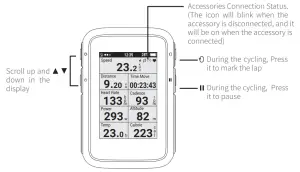
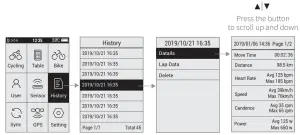
  | It’s available to scroll the page up and down by pressing the button IIt’s not available to scroll the page up and down by pressing the button |
 | Bluetooth accessory |
 | ANT+ accessory |
Standard Accessories
- Main Device x1

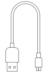
- Charging Cable x1

- User Manual x1

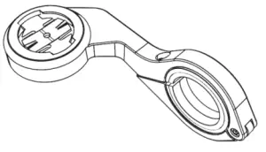
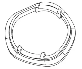
- Out Front Bike Mount x1

- Rubber Pad for Out Front Mount x2

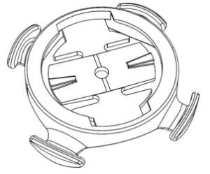
- Standard Bike Mount x1

- Rubber Pad for Standard Bike Mount x1

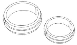
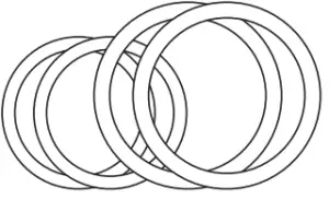
- Rubber Ring (Big x 2, Small x 2)

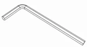
- Screw Wrench x1


How to Install
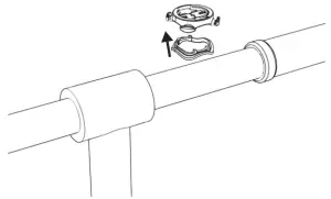
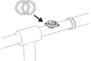
Standard Mount Installation
- Install the rubber pad onto the mount

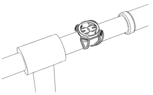
- Tie the mount onto the bar with the rubber rings

- Tie up the mount

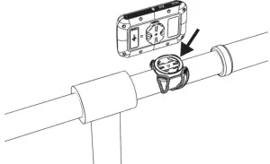
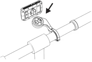
- Install the main device onto the mount

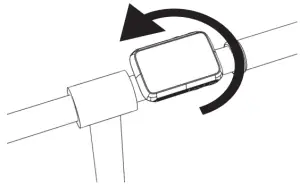
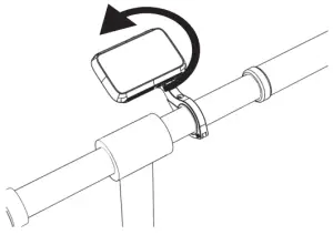
- Rotate the main device for 90 degrees

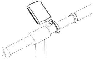
- Installation completed
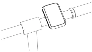
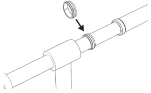
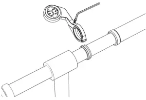
Out front mount installation
- Install the rubber pad onto the handle bar
- Unscrew the screw in the mount

- Install the mount onto the handle bar on the rubber pad, tighten up the screw

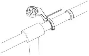
- Install the main device onto the mount

- Install the main device onto the mount

- Installation completed

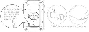
Charging
- Please charge the device before first time use.
- Please use DC 5V power adapter for charging.
- During the charging, the battery icon will flash until fully charged.

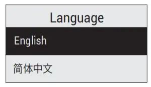
Initial Setup
- For the 1st time use, please select the language before use.

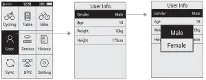
- User Profile Setting (To make the exercise calculation more accurate, please set the user profile correctly)

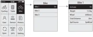
- Bike Profile Setting.

Total Distance: Select and confirm to reset the total distance
Speed Source: Set the priority for the source of the speed
Common wheel size and circumference(Wheel Size L (mm))
- 12 × 1.75 935mm
- 14 × 1.5 1020mm
- 14 × 1.75 1055mm
- 16 × 1.5 1185mm
- 16 × 1.75 1195mm
- 18 × 1.5 1340mm
- 18 × 1.75 1350mm
- 20 × 1.75 1515mm
- 20 × 1-3/8 1615mm
- 22 × 1-3/8 1770mm
- 22 × 1-1/2 1785mm
- 24 × 1 1753mm
- 24×3/4 Tubular 1785mm
- 24 × 1-1/8 1795mm
- 24 × 1-1/4 1905mm
- 24 × 1.75 1890mm
- 24 × 2.00 1925mm
- 24 × 2.125 1965mm
- 26 × 1.75 2023mm
- 26 × 1.95 2050mm
- 26 × 2.00 2055mm
- 26 × 2.10 2068mm
- 26 × 2.125 2070mm
- 26 × 2.35 2083mm
- 26 × 3.00 2170mm
- 26 × 7/8 1920mm
- 26 × 1(59) 1913mm
- 26 × 1(65) 1952mm
- 26 × 1.25 1953mm
- 26 × 1-1/8 1970mm
- 26 × 1-3/8 2068mm
- 26 × 1-1/2 2100mm
- 26 × 1.40 2005mm
- 26 × 1.50 2010mm
- 27 × 1 2145mm
- 27 × 1-1/8 2155mm
- 27 × 1-1/4 2161mm
- 27 × 1-3/8 2169mm
- 27.5×1.75 2114mm
- 27.5×2.125 2174mm
- 27.5×1.5 2074mm
- 27.5×1.95 2146mm
- 29×2.1 2288mm
- 29×2.2 2298mm
- 29×2.3 2326mm
- 650× 35A 2090mm
- 650 × 38A 2125mm
- 650 × 38B 2105mm
- 700 × 18C 2070mm
- 700 × 19C 2080mm
- 700 × 20C 2086mm
- 700 × 23C 2096mm
- 700 × 25C 2105mm
- 700 × 28C 2136mm
- 700 × 30C 2170mm
- 700 × 32C 2155mm
- 700C Tubular 2130mm
- 700 × 35C 2168mm
- 700 × 38C 2180mm
- 700 × 40C 2200mm
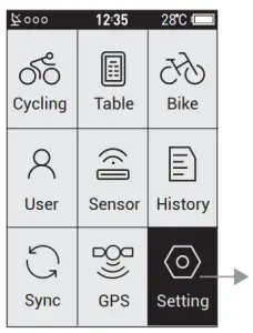
Other Settings
Zone:
Set the value for each heart rate zones, power zones, and cadence zones
Alarm:
Set the alarm for heart rate, power and cadence. The device will beep if it reached to the preset value, and a warning message will pop up during the cycling.
Smart Pause:
When this function is turned on, the cycling recording will be paused automatically when the speed is 0. It will get resumed when the speed is detected.
Altitude:
Set the numbers here to calibrate the current altitude.
Smart Lap:
Set the location or the distance used for smart lap counting.
Tone:
Set the key tone and the warning tone.
Back Light:
Set the mode of how to turn the back light off and the brightness
Unit:
Set the unit to Metric System or Imperial System.
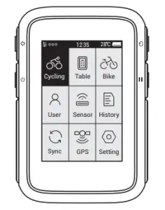
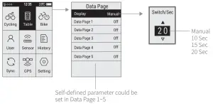
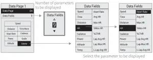
Page Setting
- Set the display content in page setting.

- The content to be displayed in self-defined page

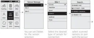
Connecting the Sensors
Please make sure the sensors are in wake-up mode( for example the heart rate monitor should be worn properly, for cadence, speed, and power sensor, rotate the crank or the wheel to wake it up).
Connection completed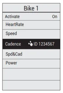
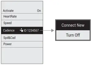
Add New Sensor and Turn off Old Sensor
Select the desired sensor, and then select to connect new sensor or turn off the old sensor in the popped up window
Power Calibration
Select Power, and then select Calibrate in the popped up window
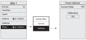
Power calibration only works in ANT+ power meter, the Bluetooth power meter doesn’t support this function.
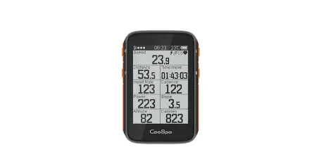
Starting a Ride
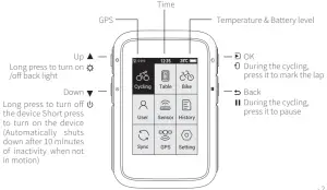
Display and Button
View History
Sync Data
USB connection
- Turn on the device’s sync function “USB connection”.
- Connect the device to the computer with USB cable.
- Computer will recognize the device as a new disk, find the folder “fit activity” , and copy the files in the folder to the computer
- Upload the activity file(.fit) to www.strava.com to view the data.

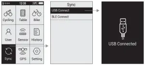
Bluetooth Connection
- Download CoospoRide in Google Play or App Store


Applicable Smart Phones IOS 7.0 or above, iPhone 4s model or above
 Android 4.3 or above with Bluetooth 4.0
 - Go to‘Sync’on bike computer, select‘BLE Connect’ to enable Bluetooth
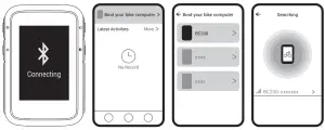
- Open Coosporide app, turn on phone Bluetooth, go to‘ bind your computer’
- Select BC200 to enter searching status
- Click BC200-xxxxxxx to connect


Specifications
| Display | LCD, 2.4 in | Backlight | Yes |
| File Transfer | USB/Bluetooth(APP) | Parameters Diaplayed Each Page | 2-9 |
| Wireless | Bluetooth & ANT+ | Language | Spainish/Russian German/Portuguese French/Turkish/English |
| Battery Type | 1300 mAh | GPS | GPS & BDS & Glonass |
| Self-Defined Display | 5 pages | Parameter Diaplayed | 70+ |
| Size | 60 x 88 x 20 mm | Laps Count | Yes |
| Waterproof | IP67 | Zone Alert | Yes |
| Storage Format | .fit File | Battery Life | GPS 36 hours continuous use |
| Supported Devices | ANT+ & BLE : Heart Rate Monitor, Speed Sensor, Cadence Sensor, Speed & Cadence 2 in 1 Sensor, Power Meter | ||
Attentions
The information contained in this manual is forreference only. The product described above may be subject to alteration owing to the manufacturer’s continuing research and development plans without prior notice.
Disclaimer
The information contained in this manual just for reference. The product described above may be subject to alteration owing to the manufacturer’s continuing research and development plans, without making an announcement in advance.
We shall not bare any legal responsibility for any direct or indirect, accidental or special damages, losses and expenses arising from or in connection with this manual or the contained product.
FCC statement
This equipment has been tested and found to comply with the limits for a Class B digital device, pursuant to part 15 of the FCC Rules. These limits are designed to provide reasonable protection against harmful interference in a residential installation. This equipment generates uses and can radiate radio frequency energy and, if not installed and used in accordance with the instructions, may cause harmful interference to radio communications. However, there is no guarantee that interference will not occur in a particular installation. If this equipment does cause harmful interference to radio or television reception, which can be determined by turning the equipment off and on, the user is encouraged to try to correct the interference by one or more of the following measures:
- Reorient or relocate the receiving antenna.
- Increase the separation between the equipment and receiver.
- Connect the equipment into an outlet on a circuit different from that to which the receiver is connected.
- Consult the dealer or an experienced radio/TV technician for help.
Changes or modifications not expressly approved by the party responsible for compliance could void the user’s authority to operate the equipment.
This device complies with Part 15 of the FCC Rules. Operation is subject to the following two conditions:
- this device may not cause harmful interference, and .
- this device must accept any interference received, including interference that may cause undesired operation.
IC statement
This device contains licence-exempt transmitter(s)/receiver(s) that comply with Innovation, Science and Economic Development Canada’s licence-exempt RSS(s). Operation is subject to the following two conditions:
- This device may not cause interference.
- This device must accept any interference, including interference that may cause undesired operation of the device
![]() Waste electrical products should not be disposed of with household waste. Please recycle where facilities exist. Contact your local government or a retailer for additional information.
Waste electrical products should not be disposed of with household waste. Please recycle where facilities exist. Contact your local government or a retailer for additional information.
- Do not open or modify the product.
- Do not disassemble or attempt to service this product.
- This product is safe under normal and reasonably foreseeable operating conditions.
- If product is operating improperly, call COOSPO support.
- Product must be returned to the manufacturer for any service or repair.


