![]() User Manual
User Manual
PRODUCT NAME
Wireless module
MODEL / Series / Product Number
P5740-162
SMC Corporation
Caution
Notice:
Changes or modifications not expressly approved by the manufacturer could void the user’s authority to operate the equipment.
NOTE:
This equipment has been tested and found to comply with the limits for a Class B digital device, pursuant to part 15 of the FCC rules. These limits are designed to provide reasonable protection against harmful interference in a residential installation. This equipment generates, uses, and can radiate radio frequency energy and, if not installed and used in accordance with the instructions, may cause harmful interference to radio communications. However, there is no guarantee that interference will not occur in a particular
installation. If this equipment does cause harmful interference to radio or television reception, which can be determined by turning the equipment off and on, the user is encouraged to try to correct the interference by one or more of the following measures:
- Reorient or relocate the receiving antenna.
- Increase the separation between the equipment and receiver.
- Connect the equipment into an outlet on a circuit different from that to which the receiver is connected.
- Consult the dealer or an experienced radio/TV technician for help.
This equipment has been tested and found to comply with Part 15 of the FCC Rules. Operation is subject to the following two conditions:
(1) This device may not cause harmful interference
(2) This device must accept any interference received, including interference that may cause undesired operation.
This device complies with part 15 of the FCC Rules. Operation is subject to the following two conditions:
(1) this device may not cause harmful interference, and (2) this device must accept any interference received, including interference that may cause undesired operation.
This device is authorized under Title 47 CFR 15.519 (the FCC Rules and Regulations).
The operation of this device is subject to the following restriction:
The changes or substitutions of the antennas which are furnished with the device are prohibited.
FCC ID : 2AJE7SMC-WEX07 IC: 21344-WEX07
This device complies with Industry Canada license-exempt RSS standard(s). Operation is subject to the following two conditions: (1) this device may not cause interference, and (2) this device must accept any interference, including interference that may cause undesired operation of the device.
![]() Caution
Caution
This device and its antenna(s) must not be co-located or operated in conjunction with any other antenna or transmitter. Changes or modifications not expressly approved by the party responsible for compliance could void the user’s authority to operate the equipment. The antenna must be installed by a professional.
“Operation is subject to the following two conditions: (1) this device may not cause interference, and (2) this device must accept any interference, including interference that may cause undesired operation of the device.”
“This Class B digital apparatus complies with Canadian ICES-003.”
“This device and its antenna(s) must not be co-located or operating in conjunction with any other antenna or transmitter.”
Cet appareil et son antenne (s) ne doit pas être co-localisés ou fonctionnant en conjonction avec une autre antenne ou transmetteur.
“This equipment should be installed and operated with a minimum distance of 20cm between the radiator and your body”
End Product Labeling
This transmitter module is authorized only for use in devices where the antenna may be installed such that 20cm may be maintained between the antenna and users. The final end product must be labeled in a visible area with the following: “Contains FCC ID: 2AJE7SMC-WEX07 ” and “Contains IC: 21344-WEX07 “
Information for the OEMs and Integrators
The following statement must be included with all versions of this document supplied to an OEM or integrator, but should not be distributed to the end-user.
1) This device is intended for OEM integrators only.
2) Please see the full Grant of Equipment document for other restrictions.
This radio transmitter FCC ID: 2AJE7SMC-WEX07 and IC: 21344-WEX07 has been approved by FCC to operate with the antenna types listed below with the maximum permissible gain and required antenna impedance for each antenna type indicated. Antenna types not included in this list, having a gain greater than the maximum gain indicated for that type, are strictly prohibited for use with this device.
Antenna list
| No. | Manufacturer | Part No. | Antenna Type | Peak Gain |
| 1 | SMC | P5740-162 | PCB Antenna | 1.83 dBi for 2.4 GHz |
| 2 | SMC | P5740-164 | whip Antenna | 1.49 dBi for 2.4 GHz |
Introduction
P5740-162 is a wireless module that provides an SPI interface for MCU communication.It comes with the SMC original protocol using the 2.4GHz ISM band.
The frequency hopping period and the data rate can be switched between 2ms(1000kbps) / 5ms(250kbps). Moreover, the frequency channel numbers can be selected from 5 to 79.
Specification
| Wireless module model No. | P5740-162 |
| Wireless module version | Hardware: Ver.1.00 Wireless software: Ver.1.00 |
| Frequency range | 2.4GHz (2403MHz ~ 2481MHz) |
| Frequency Channel | 79ch~15ch (ch separation min.1MHz) |
| Protocol | SMC original protocol |
| Encryption | SMC original encryption |
| Radio wave type | Frequency Hopping Spread Spectrum (FHSS) |
| Output level | 20dBm eirp |
| CCA | Adaptive |
| Modulation | GFSK |
| Data Rate | 1000kbps / 250 kbps |
| Deviation | 250kHz(1000kbps) / 62.5kHz(250kbps) |
| Frequency hopping period | 2ms(1000kbps) / 5ms(250kbps) |
| Antenna | PCB antenna(1.83dBi) / Whip antenna(1.49dBi) |
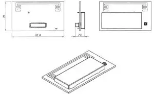
| Dimensions | 42.4 x 24.0 x 7.8mm |
| Weight | 5g |
| Ambient operating temperature | -10 to +50oC |
| Ambient storage temperature | -20 to +60oC |
| Ambient humidity | 35 to 85% RH (no condensation) |
| Power supply voltage | 3.3 VDC ±5% |
| Current consumption | 90mA |
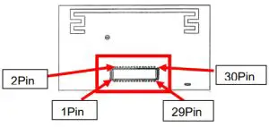
Pin Description
| Pin No. | Name | Description |
| 1 | 3.3V_C | VCC +3.3V DC |
| 2 | N.C. | No Connection |
| 3 | 3.3V_C | VCC +3.3V DC |
| 4 | N.C. | No Connection |
| 5 | NIRO | I2C interrupt: Output |
| 6 | PB11 | Digital I/O |
| 7 | PB12 | Digital I/O |
| 8 | PB13 | Digital I/O |
| 9 | PC11 | Digital I/O |
| 10 | PF4 | Digital I/O |
| 11 | PF7 | Digital I/O |
| 12 | N.C. | No Connection |
| 13 | EFR_RQ1 | Request from MCU: Input |
| 14 | I2C0_SDA | I2C Data : Input/Output |
| 15 | EFR_RQ2 | Request to MCU: Output |
| 16 | I2C0_SCL | I2C Clock: Output |
| 17 | N.C. | No Connection |
| 18 | BUSBY_BUSAX | Analog I/O |
| 19 | OPA0_P | Analog I/O |
| 20 | OPA0_N | Analog I/O |
| 21 | OPA0_OUT | Analog I/O |
| 22 | N.C. | No Connection |
| 23 | US0_CS | SPI Chip Select: Input |
| 24 | US0_RX | SPI Rx: Input |
| 25 | US0_TX | SPI Tx: Output |
| 26 | US0_CLK | SPI Clock: input |
| 27 | N.C. | No Connection |
| 28 | 0V_US1 | Ground |
| 29 | N.C. | No Connection |
| 30 | 0V_US1 | Ground |
Dimensions
•P5740-162
SMC Corporation
4-14-1, Sotokanda, Chiyoda-ku, Tokyo 101-0021 JAPTel: + 81 3 5207 8249 Fax: +81 3 5298 5362
URL http://www.smcworld.com
Note: Specifications are subject to change without prior notice and any obligation on the part of the manufacturer.
© 2021 SMC Corporation All Rights Reserved


