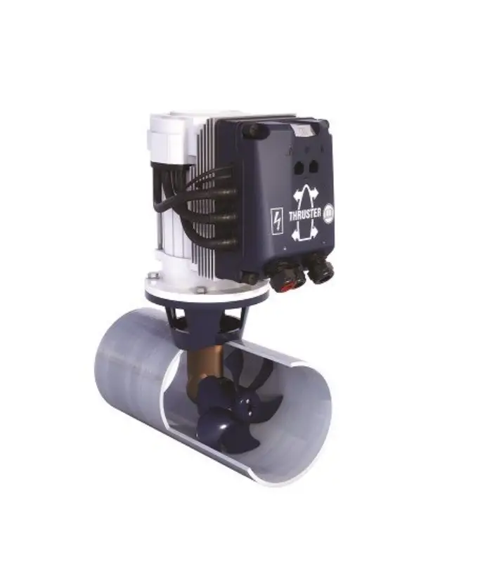
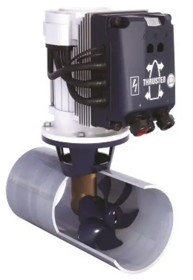
vetus BOWB150 BOW PRO ‘B’ Series Thrusters
Safety
Warning indications
The following warning indications are used in this manual in the context of safety:
 Danger
Indicates that great potential danger exists that can lead to serious injury or death.
Warning
Indicates that a potential danger that can lead to injury exists.
 Caution
Indicates that the usage procedures, actions etc. concerned can result in serious damage to property. Some CAUTION indications also advise that a potential danger exists that can lead to serious injury or death.
![]() Note
Note
Emphasises important procedures, circumstances etc.
Symbols
✔ Indicates that the relevant procedure must be carried out.
✘ Indicates that a particular action is forbidden.
Share these safety instructions with all users.
General rules and laws concerning safety and accident prevention must always be observed.
Introduction
This manual give guidelines for installing a VETUS bow and/or stern thruster from the BOW PRO series, model ‘BOWB150’, ‘BOWB180’ and ‘BOWB210’.
The bow or stern thruster system consists of the following basic components:
- Side thruster
- Tunnel
- Energy storage
- Energy supply
- Operation
![]() Note
Note
If necessary, consult the installation manuals for all components before putting the complete system into operation. For maintenance and warranty, please refer to the ‘Maintenance and Warranty Manual’.
The quality of installation will determine how reliably the bow and/or stern thruster performs. Almost all faults can be traced back to errors or inaccuracies during installation. It is therefore imperative that the steps given in the installation instructions are followed in full during the installation process and checked afterward.
Alterations made to the bow thruster by the user will void any liability on the part of the manufacturer for any damages that may result.
The actual thrust generated by the bow and/or stern thruster will vary from vessel to vessel depending on the windage, the hull displacement, and the shape of the underwater section.
The nominal thrust quoted can only be achieved under normal conditions:
- During use ensure the correct battery voltage is available.
- The installation is carried out in compliance with the recommendations given in this installation instruction, in particular with regard to:
- Sufficiently large diameter of the battery cables so that voltage drop is reduced to a minimum.
- The manner in which the tunnel has been connected to the hull.
- Use of bars in the tunnel openings.
These bars should only be used where this is strictly necessary (if sailing regularly in severely polluted water.) - The bars must have been fitted correctly.
![]() Note
Note
The areas in which the electric motor(s) of the thruster(s) and batteries are positioned must be dry and well ventilated.
![]() Note
Note
Check for possible leaks immediately the boat is relaunched.
![]() Note
Note
The maximum continuous length of usage and the thrust as specified in the technical details are based on the recommended battery capacities and battery cables.
Installation recommendations
Positioning of the thruster tunnel
Several installation examples.
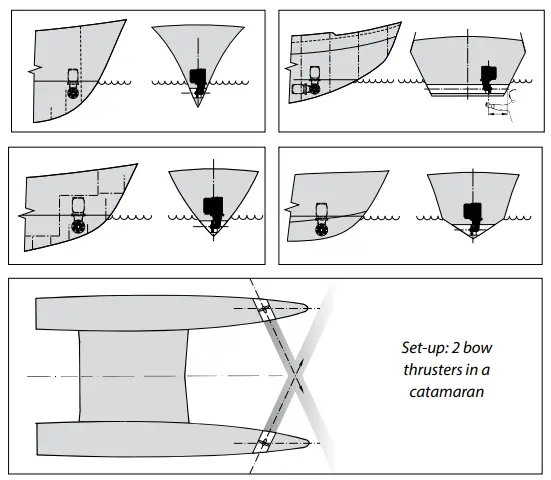
To achieve the optimum performance, position the thruster tunnel as far forward as possible
If, in addition to controlling the movement of the bow, the stern of the vessel is required to move sideways, then a second thruster may be installed at the stern.
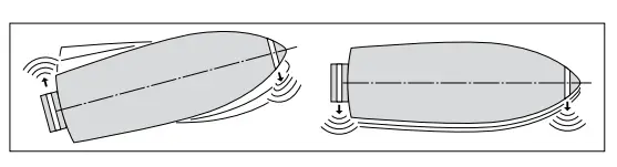
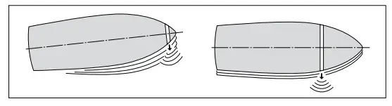
For a planning boat the tunnel should, if possible, be so situated so that when the vessel is planning it is above the water level thus causing no resistance.
Installation of two bow thrusters in tandem (for larger boats). In this case, depending on weather conditions, one or both bow thrusters may be used.
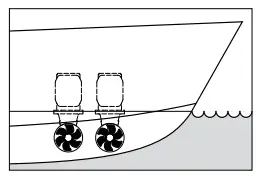
![]() Tip:
Tip:
We do not advise fitting 2 bow thrusters into one tunnel; this does not result in doubling the thrust!
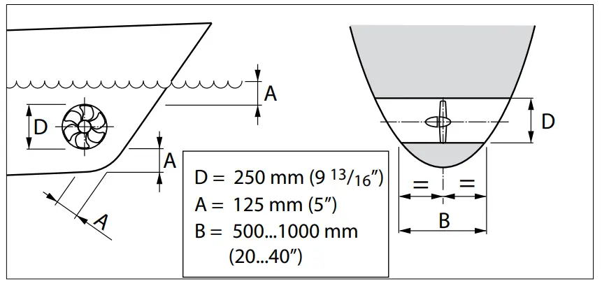
When choosing the location for the thrust tunnel, take the following into account for optimum performance:
- The distance A shown in the drawing must be at least 0.5 x D (where D is the tunnel diameter).
- The length of the tunnel (distance B) should be between 2 x D and 4 x D.

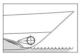
Positioning of the bow thruster in the thrust-tunnel
When determining the exact position of the bow thruster in the thrust tunnel, the tailpiece MUST NOT protrude from the tunnel end.
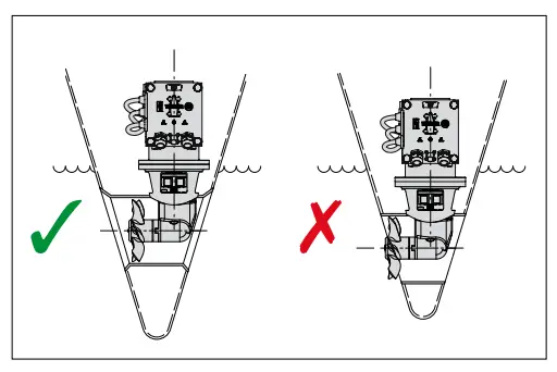
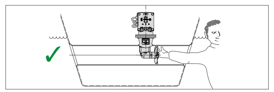
The propeller should preferably be situated on the centreline of the vessel, but it must always be accessible from the outside.
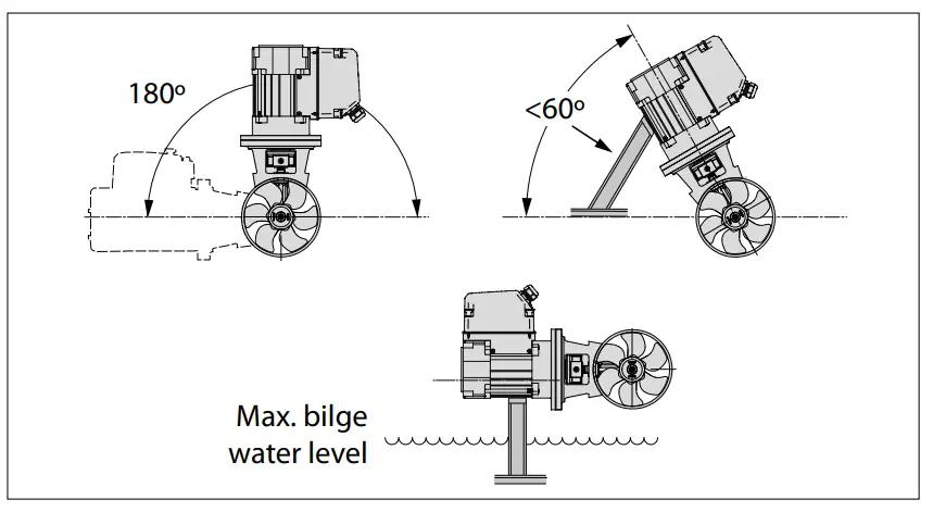
- The electric motor can be installed in various positions.
- If the motor is set up horizontally or at an angle, support is absolutely essential.
- The electric motor must be positioned in such a way that it is always well clear from the maximum bilge water level.
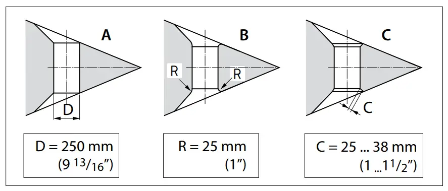
Connection of thrust tunnel to ship’s hull
Direct connection of the tunnel to the hull, without a fairing, produces reasonable results
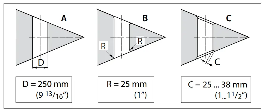
A The connection to the hull can be abrupt.
B It is better to make the connection rounded with radius ‘R’ of about 0.1 x D.
C It is even better to use sloping sides ‘C’ with dimensions 0.1 to 0.15 x D.
Connection of the thrust tunnel to the ship’s hull with a fairing results in lower hull-resistance during normal sailing.
A The connection with a fairing can be abrupt.
B It is better to make the connection with a fairing rounded with radius ‘R’ of about 0.1 x D.
C The best connection is with a fairing using sloping side ‘C’ with dimensions 0.1 to 0.15 x D.
![]() Tip:
Tip:
The manner, in which the thrust tunnel is connected to the hull, has a great influence on the actual performance of the bow thruster and to the drag the hull experiences when underway
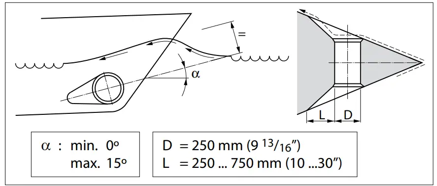
- Length ‘L’ of the fairing should be between 1 x D and 3 x D.
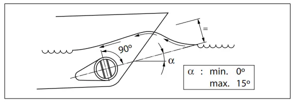
- This fairing should be embodied in the ship’s hull in such a way that the centreline of the fairing will correspond with the anticipated shape of the bow-wave.
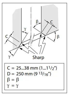
If the connection of the thrust tunnel and the boat’s hull is to be made with a sloped side, it should be executed in accordance with the drawing.
Make the sloped side (C) with a length of 0.1 to 0.15 x D and make sure that the angle between the tunnel and the sloped side will be identical to the angle between the sloped side and the ship’s hull.
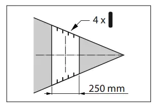
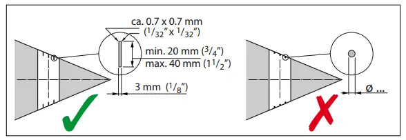
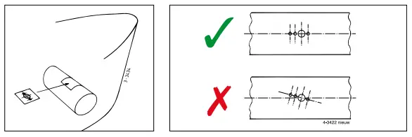
Grid bars in the tunnel openings
Although the thrust force will be adversely affected, grid bars may be placed into the tunnel openings, for protection of the thruster.
In order to limit the negative effect of this on the thrust and on hull resistance during normal operation as much as possible, the following must be taken into account:
- Do not fit more bars per opening than is indicated in the drawing.


- The bars must have a rectangular cross-section.
- Do not fit round bars
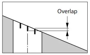
- The bars must overlap a certain amount.


- The bars must be installed so they are perpendicular to the expected waveform.
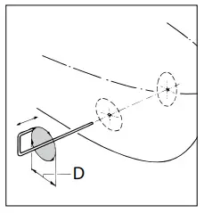
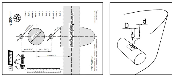
Installation of the thrust tunnel
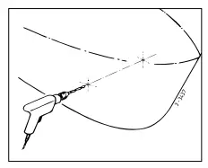
- Drill 2 holes in the hull, where the centreline of the thrust tunnel will be, in accordance with the diameter of the marking tool.

- Pass the marking tool (home-made) through both pre-drilled holes and mark the outside diameter of the thrust-tunnel on the hull.

D [mm] (inches)
Steel GRP Aluminium 267
(10 33/64”)265.6
(10 7/16”)264
(10 25/64”) - Dependent on the vessel’s construction material, cut out the holes by means of a jigsaw or an oxy-acetylene cutter.

- Install the thrust-tunnel.
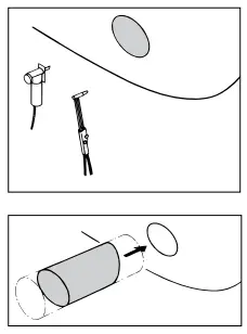
Polyester thrust tunnel:
Resin: The resin used for the polyester thrust tunnel is Isophtalic polyester resin (Norpol Pl 2857).
Pre-treatment: The outside of the tunnel must be roughened. Remove all of the top surface down to the glass-fibre. Use a grinding disc for this.
Important: After the tunnel been sawn to length, treat the end of the tube with resin. This will prevent water seeping in.
Laminating: Apply a coat of resin as the first coat. Lay on a glassfibre mat and impregnate with resin. Repeat this procedure until you have built up a sufficient number of layers.
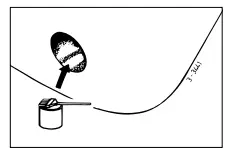
A polyester thrust tunnel should be finished as follows:
- Roughen the hardened resin/glass-fibre. Apply a top coat of resin
- Treat the side of the tunnel which comes into contact with water with ‘epoxy paint’ or 2-component polyurethane paint.
- Then apply anti-fouling treatment if required.

Drilling the holes in the thrust-tunnel
- Mark the installation position of the bow thruster by means of the intermediate flange.
- Use the drill pattern supplied, to determine the correct position of the holes to be drilled.

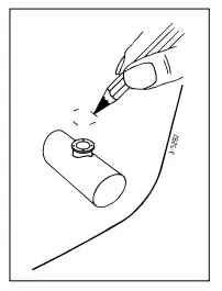
Important: The pattern of the holes must be positioned precisely on the centreline of the tunnel.
Consult the template for the dimensions of the holes to be drilled. Drill the holes through the thrust tunnel and take care that the holes are free of burrs.
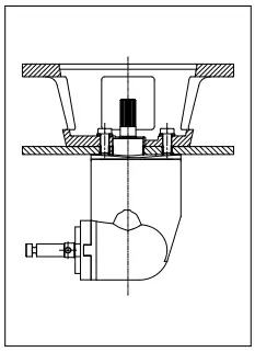
Protection of the bow thruster against corrosion
To prevent corrosion problems, do not use copper based antifouling. Cathodic protection is a ‘must’ for the protection of all metal parts under water and the bow thruster is supplied with a zinc anode for this purpose.
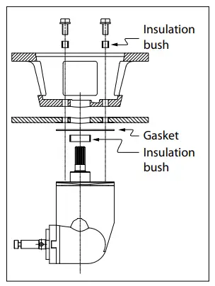
Corrosion of a steel or aluminium thrust tunnel can be reduced by ensuring that the tail piece is completely insulated from the thrust-tunnel.
NOTE: The gaskets supplied are already electrically insulated. However the bolts and the shaft need to be fitted with insulation material, for example nylon bushes.
Installation
Introduction
![]() Note
Note
The areas in which the electric motor(s) of the bow thruster(s) and the batteries are positioned must be dry and well ventilated.
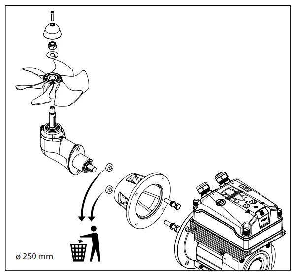
The bow thruster is supplied in parts as shown.
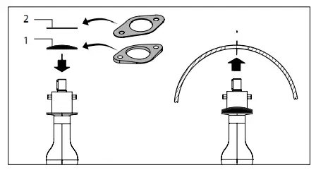
Installation tailpiece and intermediate flange
- Ensure that the plastic shim plate (1) has been positioned on the tail piece.
- Place one packing (2) between the tail piece and the tunnel.
- Apply a sealant (e.g. polyurethane or silicone) between the tail
piece and packing, and between the packing and the tunnel wall. - Place the tail piece in the hole in the tunnel. Any extra packings used should be ones capable of justifying the tail piece. *) e.g. Sikaflex®-292.

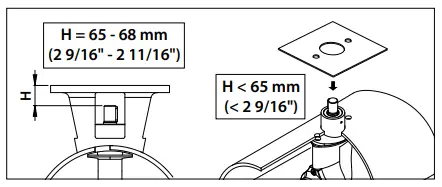
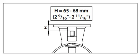
- Grease the hole of the intermediate flange and position this flange.
- Check dimension ‘H’; it must be between 65 and 68 mm (between 2 9/16” and 2 11/16”)
- If the dimension ‘H’ is less than 65 mm (2 9/16”), fit an additional gasket between the thrust tunnel and the intermediate flange.
- Check again dimension ‘H’.

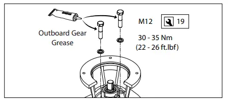
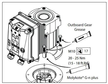
- Now fit the intermediate flange permanently to the tail piece and grease the threads of the bolts with ‘outboard gear grease’ *) before inserting and tightening them.

Final assembly
- Check again dimension ‘H’

- Make sure that the key (1) is properly positioned in the keyway of the shaft.
- Grease the shaft with ‘outboard gear grease’ and install the propeller (2) with the lock washer (3) and the hexagonal nut (4).
- Secure the nut by bending the tag of the washer.
- Fit the zinc anode (5) to the propeller shaft by means of the bolt (6)

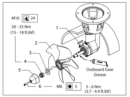
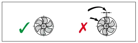
The propeller should run a minimum of 1.5 mm (1/16”) free of the thrust tube wall, all round.
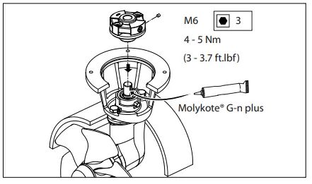
- Grease the input shaft with an installation compound, like ‘Molykote® G-n plus’
- Fit the flexible coupling to the input shaft of the tail piece and secure the coupling with the locking screw.

- Grease the shaft of the electric motor with an installation compound, like ‘Molykote® G-n plus’.
- Grease the threads of the fastenings bolts with ‘outboard gear grease’ *) and install the electric motor to the intermediate flange.
- For a first check, turn the propeller by hand, it should turn easily, whilst being connected to the output spindle of the electric motor.
*) A suitable grease is VETUS ‘Shipping Grease’, Art. code: VSG
Electrical installation
Choice of battery
The total battery capacity must be sufficient for the size of the bow thruster; see the table. See page 116 for the applicable battery capacity.
The minimum battery capacity is specified in the table; with a larger battery capacity, the bow thruster will perform even better!
We recommend VETUS maintenance free marine batteries; these can be supplied in the following sizes: 55 Ah, 70 Ah, 90 Ah, 108 Ah, 120 Ah, 143 Ah, 165 Ah, 200 Ah and 225 Ah.
We also recommend that each bow thruster is powered by its own separate battery or batteries. This allows the battery bank to be placed as close as possible to the bow thruster; the main power cables can then be short thus preventing voltage losses caused by long cables.
Always use batteries whose type and capacity are compatible for their use.
![]() Note
Note 
Be sure to only use ‘sealed’ batteries if the batteries are located in the same compartment as the bow thruster. VETUS ‘SMF’ and ‘AGM’ maintenance-free batteries are ideal for this application. Batteries that are not ‘sealed’ may produce small amounts of explosive gas during the charging cycle.
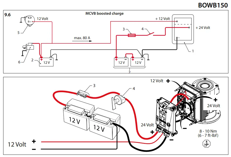
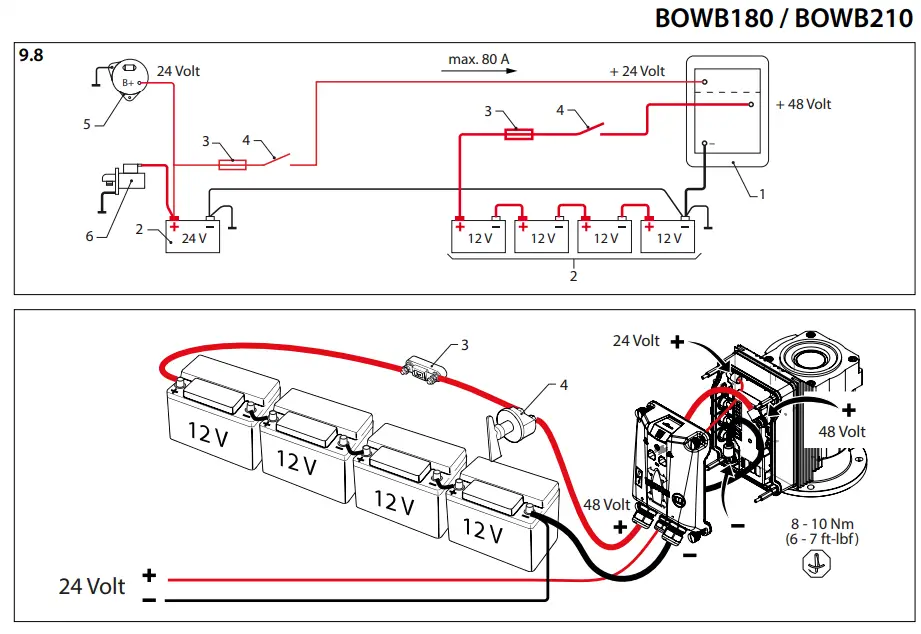
MCVB boosted charge function
Using the MCVB boosted charge function, the 48 Volt motor can be used in an (existing) 24 V on-board power grid.
By connecting the 24 Volt battery bank to the MCVB boosted charge connection, the 48 Volt, battery bank is charged. An additional charging facility is not required. See page 113 for the connection diagram.
![]() Note
Note
As a standard, the MCVB boosted charge function is only suitable for Lead acid batteries
Main power cables (battery cables)
The minimum diameter and battery capacity must be sufficient for the bow thruster’s current draw in use. Consult the table on page 116 for the correct values
![]() Note
Note
The maximum operating time and the thrust, as specified by the technical details in your bow thruster installation and operating manual, are based on the recommended battery capacities and battery connection cables.
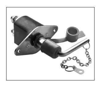
Main switch
The main switch must be fitted to the ‘positive cable’. The VETUS battery switch type BATSW250 is a suitable switch, which is also available in a 2-pole version, VETUS part number BATSW250T.
Fuses
Main power fuse 1
A fuse must be included in the ‘positive cable’ for the main switch, as close to the battery as possible. This fuse protects the on-board power cabling from short circuits.
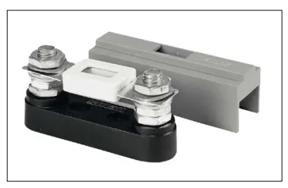
For all fuses we can suppy a fuse holder, VETUS part no.: ZEHC100. See page 116 for the size of the fuse to be used.
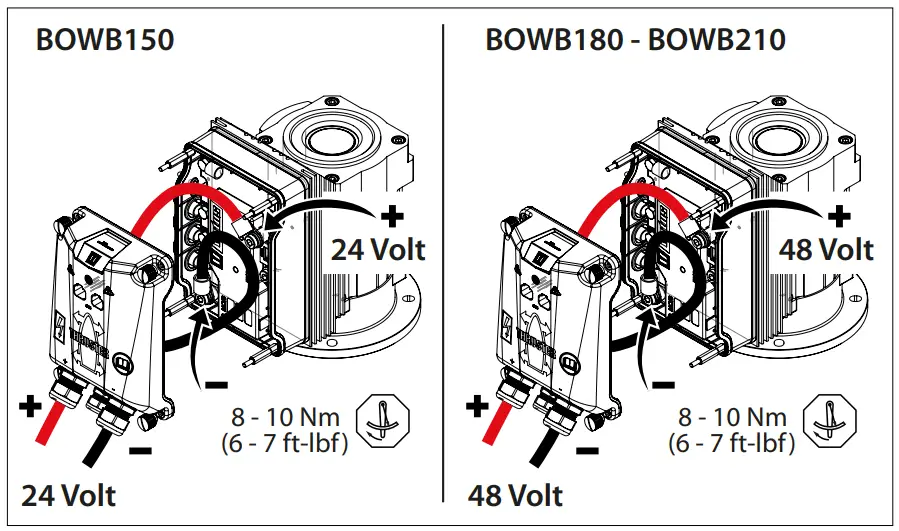
Connecting the main power cables and configuring the bow and/or stern thruster
Make sure that no other electrical parts come loose when connecting the electric cables.
Check all electrical connections after 14 days. Electrical parts (such as bolts and nuts) may come loose as a result of fluctuations in temperature.
- Take off the cover.
- Feed the battery cables through the input glands in the cover.
- Apply cable terminals to the battery cables and connect the cables to the motor controller.
Make sure that the cable terminal on the negative cable cannot cause a short circuit to the lowest of the three motor connections on the controller!
![]() Note
Note
The tightening torque of bolts in the motor regulator is a maximum of 10 Nm (7 ft-lbf).
The drawing shows how the cables must be laid in order for the cover to be replaced again.
![]() Note
Note
Make sure that the voltage stated on the motor type plate is identical to the boat’s power supply voltage
![]() Note
Note
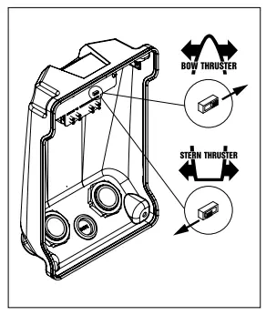
To allow the bow thruster or stern thruster to be distinguished on the CAN bus, these must be configured appropriately
Bow thruster
The configuration as supplied is for application as a bow thruster.
Stern thruster
Configure a stern thruster by putting the switch on the inside of the cover into the correct position.
- Reinstall the cover and tighten the glands.

Main power fuse 2
In the connection unit, there is a main power fuse on the controller. This fuse protects the controller and motor against short circuit/overloading and it must remain present under all circumstances.
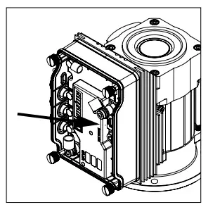
![]() Note
Note
When replacing the fuse, the replacement must be of the same rating.
Connecting CAN bus (control current) cables
See diagrams from page 107 if multiple panels have to be connected
![]() Note
Note
The CAN bus power supply must always be connected to 12 Volt (≥10 V, ≤16 V). Use the E-Drive MPE1KB key switch as power supply.
Caution
As required by international standards, all neutral (negative) conductors of the DC system must be connected to one central point. This prevents not only dangerous situations and corrosion problems, but also error messages in the CAN bus system.
Troubleshooting
Please note that his is a general instruction. Specific actions may slightly differ from one type to another.
Check, and if necessary correct, the following items if the system is not working properly.
CAN bus system
- Is the power supply switched on?
- Is the CAN bus supply voltage correct? (=12VDC).
- Does the control panel switch on?
- Are both terminating resistors correctly positioned?
Note: The CAN bus power supply has an integrated terminating resistor. - Did all connectors “click” when inserted in the connection point?
- Are the correct CAN bus cables used and in good condition?
- Are the correct CAN bus connectors used and in good condition?
- Does the total length of the CAN bus network not exceed 40 meters?
- Is each “node” connected to the power supply? Check by measuring the voltage on the 2 opposite pins in the connector on the node (pin 1=12 VDC positive, pin 3=12 VDC neutral).
Thruster installation
- Is the battery supply switched on?
- Is the supply voltage of the thruster correct? (measure the voltage at the motor controller terminals).
- Is the thruster correctly configured? (bow or stern thruster).
- Do both the positive and neutral cables have the correct diameter and length?
- Are both the positive and neutral wires connected to the correct terminals of the thruster motor controller?
- Are both the positive and neutral wires correctly routed? Incorrect routing may cause the wire(s) to press against the circuit board, which can lead to malfunctions.
- Is the pressed cable lug of the neutral cable isolated from the nearby motor winding connections? (spacer ring installed?)
Note: Not applicable to bow thrusters with external cable connections. - Are the cable glands of the power supply cables firmly tightened?
- Is the white connector for the thermal sensor of the motor correctly connected to the circuit board under the top cover?
- Is the fuse (5 A) of the motor controller in place?
- Is the connector running from the top cover circuit board to the thruster motor controller fixed and are all connector pins correctly connected? (latch in place?)
Technical data
| Type | BOWB150 | BOW8 180 | BOWB210 |
| Electric motor | |||
| Type | EC Motor(1SVAC-S.7k W) | AC Motor(29VAC-11kW) | AC Motor(29VAC-11kW) |
| For DC systems | 12/24V= | 24/48V= | 24/ 48V= |
| Current (1,1) | 242 A@ 24,0V | 238 A@44 V | 275 A@44 V |
| 276 A@ 21,0V | 289 A@ 42,0 V | 300A @42,0 V | |
| Power consumption | 5,S k W | 10,5 kW | 12,1 kW |
| Rati ng | 52 – 6 min . (11 | 52 • 10mln.(1) | 5-2 10 min. 111 |
| Protection | IP44 | ||
| Insulation class | F | ||
| Motor controller | |||
| MCV | MCV1224B + MCV8150 | MCV2448B + MCVB180 | MCV2448B + MCVB210 |
| Geintegreerde acculader | 12V / 80 A | 24V/80A | 24V/ /JtJA |
| Transmsision | |||
| Gears | Be vel gear heli cal teeth | ||
| Gear ratio | 2,33: 1 | ||
| Lubrication | oil bath, outboard gear oil SAE80W or EP 90 | ||
| : ca. 0.1 litre (3.4 fl.oz.) | |||
| Propeller | |||
| No. of blades | 6 | ||
| Profile | asymmetrical | ||
| Material | polyacetaal (Delrin®) | ||
| Rated thrust | 1500N (150 kgf, 330lb f) | 1800N(18tlkgf, 396Ibf) | 2100N (210kgf,463 lbf) |
| Control circuit | |||
| Fuse | Blade type fuse’ATO’5 A | ||
| Thrust-tunnel | |||
| Steel model | |||
| dimensions | O.D. ou1Slde 267 mm, wall thkkness 7.1 mm | ||
| treatment | blasted, coated with: SikaCor Steel Protect. Suitable for all kinds of protection systems. | ||
| Plasticmodel | |||
| dimensions | O .D. outside 265.6 mm, w all l hlckness62 mm | ||
| material | glass fibre reinforced polyester | ||
| Aluminium model | |||
| dimensions | O .D. out side264 mm, wall thickness7 mm | ||
| material | aluminium, 6060 or6062 (AIMg1SiCu) | ||
| Weight | |||
| Excl. thrust-tunne | 42kg(93lb s) | 44.5 kg(98 lbs) | 44.5 kg (98lbs) |
[1] S2 ‘t’ min. Activation time ‘t’ min. continuously or a max. of ‘t’ min. per hour at maximum power.
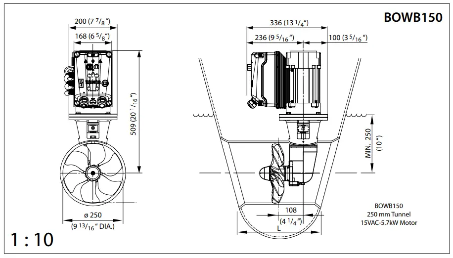
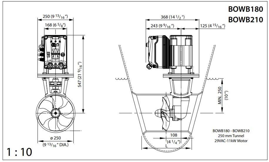
Principal dimensions
Wiring diagrams
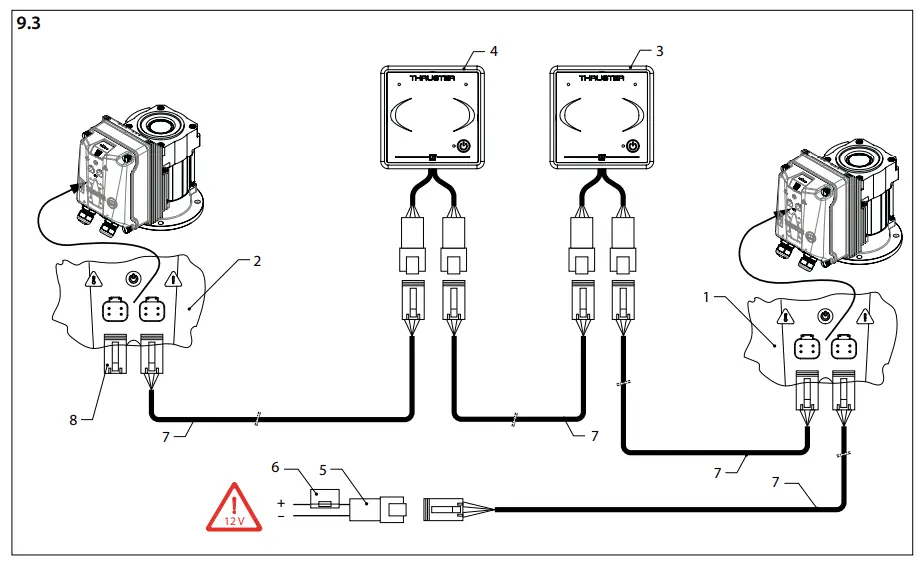
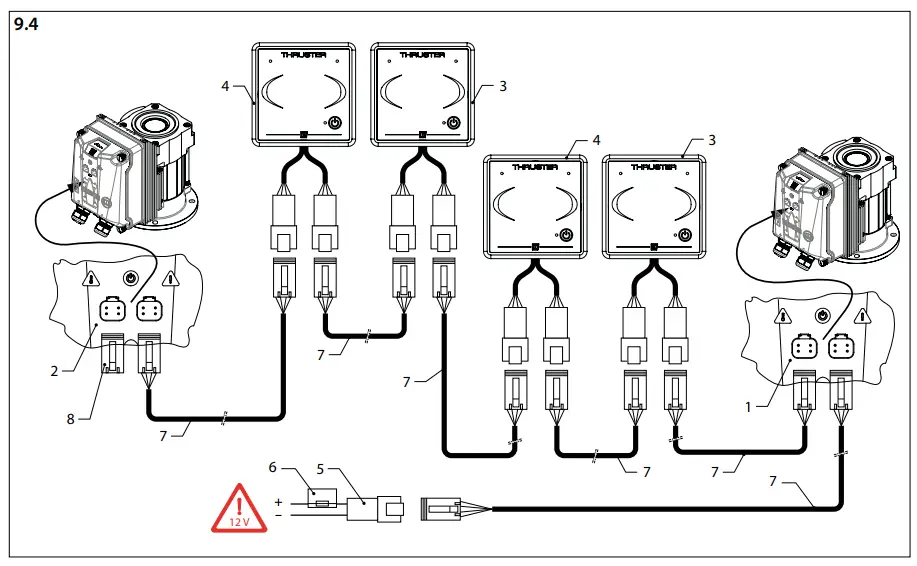
![]() Note
Note
The CAN bus is a chain to which the bow thruster and the panels are connected. At one end of the chain, the power supply (5) must be connected and the terminator (8) must be connected at the other end!
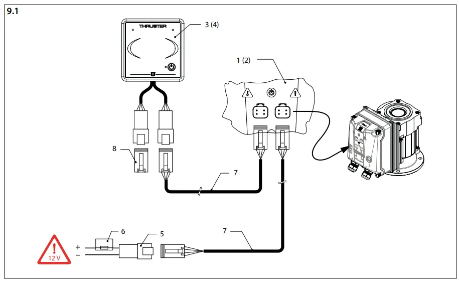
One (1) thruster (bow or stern),
One (1) helm station
- Connection box bow thruster
- Connection box stern thruster
- Control panel bow thruster
- Control panel stern thruster
- CAN-bus supply
- Control voltage fuse
- Connection cable
- Terminator

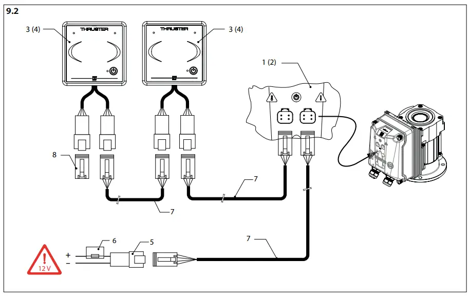
One (1) thruster (bow or stern),
Two (2) helm stations
Thrusters (bow AND stern), One (1) (8.3) or two (2) (8.4) helm stations. The diagram can be extended to up to four (4) helm stations
Connection of batteries and charging circuit with a 24 volt on-board supply
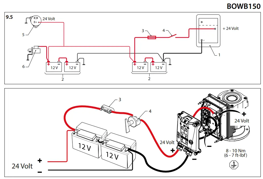
Connection box thruster (or stern thruster)
- Battery
- Main fuse
- Main switch
- Alternator
- Starter motor
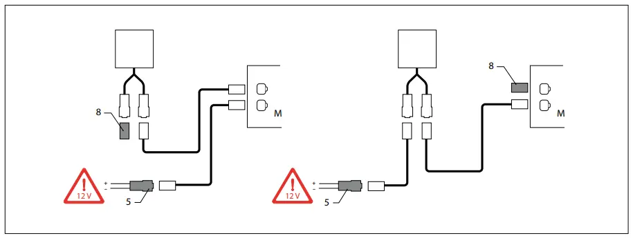
Connection of batteries and charging circuit with a 12 volt on-board supply
Connection of batteries and charging circuit with a 48 volt on-board supply
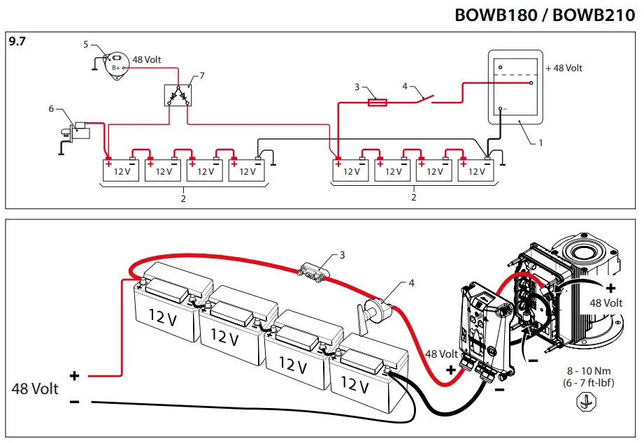
Connection box thruster (or stern thruster)
Battery
Main fuse
Main switch
Alternator
Starter motor
Battery isolator
Connection of batteries and charging circuit with a 24 volt on-board supply
Battery capacity, battery cables
|
BOWB150 150 kgf – 24 V |
2 x 170 Ah – 12 V | 0 – 6,3 m | 0 – 20,7 ft | 50 mm2 | AWG 0 |
355 A |
ZE355 |
| 6,3 – 8,7 m | 20,7 – 28,5 ft | 70 mm2 | AWG 00 | ||||
| 8,7 – 11,8 m | 28,5 – 38,7 ft | 95 mm2 | AWG 000 | ||||
| 11,8 – 14,7 m | 38,7 – 48,2 ft | 120 mm2 | AWG 0000 | ||||
| 14,7 – 17,4 m | 48,2 – 57,1 ft | 2 x 70 mm2 | 2 x AWG 00 | ||||
| 17,4 – 18,7 m | 57,1 – 61,4 ft | 150 mm2 | AWG 300 MCM | ||||
| 18,7 – 23,5 m | 61,4 – 77,1 ft | 2 x 95 mm2 | 2 x AWG 000 | ||||
| 23,5 – 29,2 m | 77,1 – 95,8 ft | 2 x 120 mm2 | 2 x AWG 0000 | ||||
| 29,2 – 37,6 m | 95,8 – 123,4 ft | 2 x 150 mm2 | 2 x AWG 300 MCM |
|
BOWB180 180 kgf – 48 V |
4 x 185 Ah – 12 V | 0 – 23,7 m | 0 – 77,8 ft | 50 mm2 | AWG 0 |
355 A |
ZE355 |
| 23,7 – 33,2 m | 77,8 – 108,9 ft | 70 mm2 | AWG 00 | ||||
| 33,2 – 45,1 m | 108,9 – 148,0 ft | 95 mm2 | AWG 000 | ||||
| 45,1 – 56,9 m | 148,0 – 186,7 ft | 120 mm2 | AWG 0000 | ||||
| 56,9 – 66,4 m | 186,7 – 217,8 ft | 2 x 70 mm2 | 2 x AWG 00 | ||||
| 66,4 – 71,2 m | 217,8 – 233,6 ft | 150 mm2 | AWG 300 MCM | ||||
| 71,2 – 90,2 m | 233,6 – 295,9 ft | 2 x 95 mm2 | 2 x AWG 000 | ||||
| 90,2 – 113,8 m | 295,9 – 373,4 ft | 2 x 120 mm2 | 2 x AWG 0000 | ||||
| 113,8 – 122,5 m | 373,4 – 401,9 ft | 2 x 150 mm2 | 2 x AWG 300 MCM |
|
BOWB210 210 kgf – 48 V |
4 x 185 Ah – 12 V | 0 – 22,9 m | 0 – 75,1 ft | 50 mm2 | AWG 0 |
355 A |
ZE355 |
| 22,9 – 32 m | 75,1 – 105 ft | 70 mm2 | AWG 00 | ||||
| 32 – 43,4 m | 105 – 142,4 ft | 95 mm2 | AWG 000 | ||||
| 43,4 – 54,9 m | 142,4 – 180,1 ft | 120 mm2 | AWG 0000 | ||||
| 54,9 – 64 m | 180,1 – 210 ft | 2 x 70 mm2 | 2 x AWG 00 | ||||
| 64 – 68,6 m | 210 – 225,1 ft | 150 mm2 | AWG 300 MCM | ||||
| 68,6 – 86,9 m | 225,1 – 285,1 ft | 2 x 95 mm2 | 2 x AWG 000 | ||||
| 86,9 – 109,7 m | 285,1 – 359,9 ft | 2 x 120 mm2 | 2 x AWG 0000 | ||||
| 109,7 – 118 m | 359,9 – 387,1 ft | 2 x 150 mm2 | 2 x AWG 300 MCM |