![]()
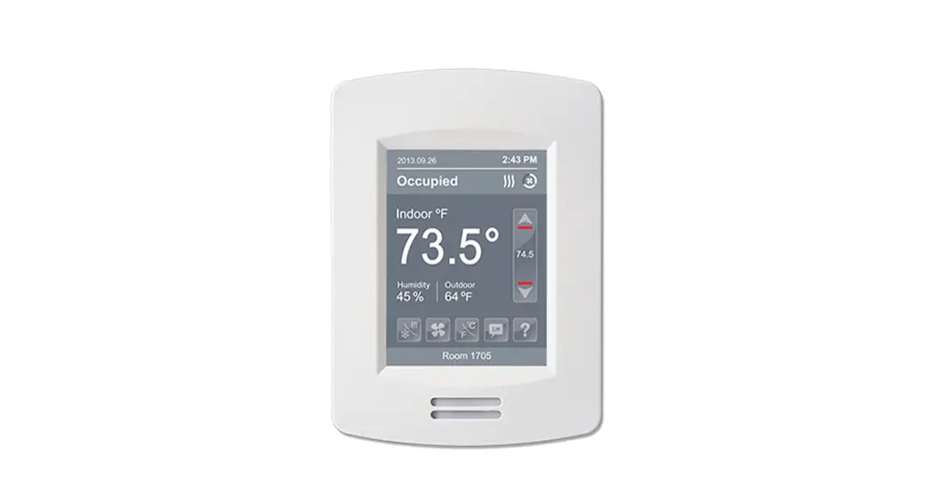
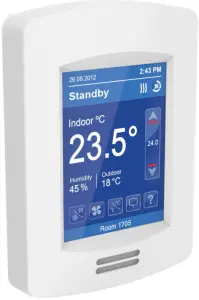
VT8000 Room Controllers
VT8650 Application Guide
Roof Top Unit (RTU), Heat Pump and
Indoor Air Quality (IAQ)
Firmware release version 2.4
OVERVIEW
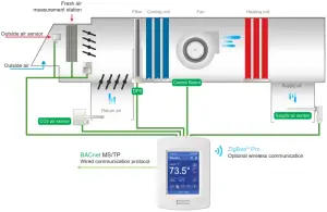
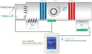
The VT8650 Rooftop and Indoor Air Quality Controller is a new, cost-effective solution for upgrading rooftop unit thermostats. This solution allows existing wiring between the rooftop unit and the temperature controller to be re-used, reducing overall costs and installation time. The VT8650 can also add new features like CO2 and fresh air monitoring to the existing functions of a rooftop unit. The VT8650 Rooftop and Indoor Air Quality Controller can be configured to handle a broad variety of applications covering all the standard implementations necessary for rooftop HVAC systems.
In addition to controlling heating, cooling, and air quality, depending on the model and accessories, the VT8650 can handle wireless networking and switches, Passive Infrared (PIR) occupancy detection using either onboard or remote sensors, and can have custom programs implemented to fulfill specific user requirements. The applications described here cover all these features, and in combination with the VT8650’s advanced scheduling and occupancy, controls can provide the functionality for any required rooftop HVAC implementation.
Commercial and Hospitality Interface (Local Override and Degrees C/F Selection)
| Part Number | Description | PIR Sensor | Humidity | ZigBee onboard | Communication |
| VT8650U5000B | RTU/HPU terminal equipment controller | No | Yes | No* | BACnet ® / Modbus ® | |
| VT8650U5500B | RTU/HPU terminal equipment controller | Yes | Yes | No* | BACnet ® / Modbus ® | |
| VT8650U5500BP | RTU/HPU terminal equipment controller | Yes | Yes | Yes | BACnet ® / Modbus ® |
*Note: ZigBee Pro plug-in module is available.
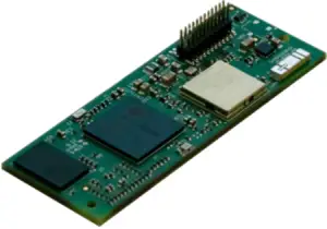
| Communication Modules for VT8650 | ||
| Part Number | Description | |
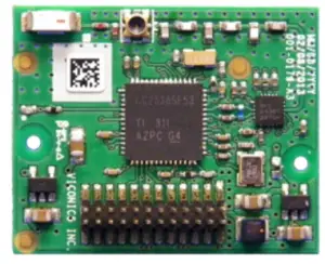 | VCM8000V5045P* Release 24 | ZigBee Pro extended profile retrofit communication module. |
 | VCM8001V5045* | CO2 detection sensor retrofits communication module. |
 | VCM8002V5031* Release 1 | Wi-Fi extended profile retrofit communication module. |
* Note: Only one of the three communication modules can be plugged in at one time.
| Wireless Accessories for VT8650* | ||
| Part Number | Description | |
 | SED-CO2-G-5045 | Wireless CO2 sensor with room temperature and humidity |
| SED-TRH-G-5045 | Wireless sensor with room temperature and humidity | |
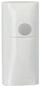 | SED-WMS-P-5045 | Wireless wall-mounted motion sensor |
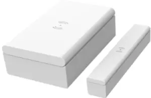 | SED-WDC-G-5045 | Wireless Window/door sensor |
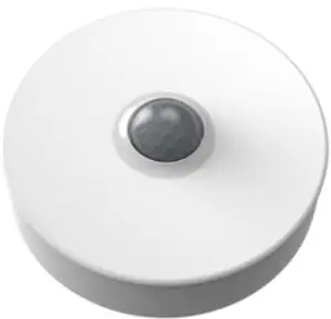 | SED-MTH-G-5045 | Wireless motion/temperature/humidity sensor |
 | SED-WLS-G-5045 | Wireless water leakage sensor |
* Note: Requires embedded ZigBee or a VCM8000V5045P.
2 HEATING / 2 COOLING FOR ROOFTOP UNIT AND INDOOR AIR QUALITY
| Configuration Parameter Name | Configuration Settings |
| UI17 | Filter |
| UI19 | CO2 |
| Econo. Config | On |
| FA Range | Set Max CFM, cannot be zero |
| Min fresh air | Set Min CFM, cannot be zero |
| Max fresh air | Set Max CFM, cannot be zero |
| Min CO2 | Set Min CO2, cannot be zero |
| Max CO2 | Set Max CO2, cannot be zero |
Note: Only required configuration parameters are listed. Other settings are configurable as needed by the user.
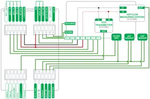
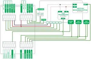
The sequence of Operation and Wiring
Occupied Mode
Setpoints revert to those defined by occupied cooling and heating.
Stand-by Mode (only available when PIR motion detector sensor is used)
Setpoints revert to those defined by stand-by cooling and heating.
Unoccupied Mode
Setpoints revert to those defined by unoccupied heating and cooling.
Occupied Override Mode
The system reverts to the occupied mode for a duration determined by the “ToccTime” parameter.
Options
• VT8650 Room Controllers that do not have a built-in wireless adapter module may be fitted with a plug-in wireless adapter module.(see Appendix A for network wiring).
• 3 universal inputs can be used and configured for advanced functionality as required by the application.
In all occupancy Modes
If a room’s relative humidity is higher than the user-defined Dehumidification setpoint, both Deum. (UO12) and Fan (BO4) outputs are energized to reach the setpoint and the thermostat`s Cooling and Heating outputs will not trigger.
*A multi-pole relay may be required to activate the Cooling and Heating stage(s).
2 COOLING / MODULATING HEAT FOR ROOFTOP UNIT AND INDOOR AIR QUALITY
| Configuration Parameter Name | Configuration Settings |
| UI17 | Filter |
| UI19 | CO2 |
| Econo. Config | On |
| FA Range | Set Max CFM, cannot be zero |
| Min fresh air | Set Min CFM, cannot be zero |
| Max fresh air | Set Max CFM, cannot be zero |
Note: Only required configuration parameters are listed. Other settings are configurable as needed by the user.
The sequence of Operation and Wiring
Occupied Mode
Setpoints revert to those defined by occupied cooling and heating.
Stand-by Mode (only available when PIR motion detector sensor is used)
Setpoints revert to those defined by stand-by cooling and heating.
Unoccupied Mode
Setpoints revert to those defined by unoccupied heating and cooling.
Occupied Override Mode
The system reverts to the occupied mode for a duration determined by the “ToccTime” parameter.
Options
• VT8650 Room Controllers that do not have a built-in wireless adapter module may be fitted with a plug-in wireless adapter module. (see Appendix A for network wiring).
• 3 universal inputs can be used and configured for advanced functionality as required by the application.
In all occupancy Modes
If a room’s relative humidity is higher than the user-defined Dehumidification setpoint, both Deum. (UO12) and Fan (BO4) outputs are energized to reach the setpoint and the thermostat`s Cooling and Heating outputs will not trigger. *A multi-pole relay may be required to activate the Cooling and Heating stage(s).
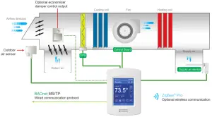
FRESH AIR DAMPER CONTROL SEQUENCESces
PRESSURE INDEPENDENT (PI)
The fresh air damper can be controlled through more than one sequence to achieve different control strategies such as free cooling (economizer mode), minimum fresh air control, and CO2 level control. Here are the control sequences available:
Note: For the sequences mentioned below, the following conditions must be met in order for the sequence
The system reverts to the occupied mode for a duration determined by the “ToccTime” parameter.
- Max Pos parameter value must be greater than Min Pos Parameter value.
- Mac CO2 parameter value must be greater than Min CO2 Parameter value.
- Max FA parameter value must be greater than Min FA Parameter value.
ECONOMIZER CONTROL MODE ONLY
If the fresh air damper is to be used only for free cooling purposes (economizer mode, without fresh air measurement station or CO2 control), only the Min Pos parameter and the free cooling sequence will be active.
• The FA Range parameter should be set to 0 CFM. (Default Value = 0 CFM)
• Set the Chngstpt parameter to desired value which free cooling is enabled. (Default Value = 55°F)
If the outside air temperature is greater than the changeover setpoint, then normal mechanical cooling will be used. If the outside air temperature is less than or equal to the changeover setpoint, then free cooling will be enabled and mechanical cooling stages will be locked out.
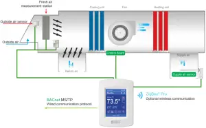
ECONOMIZER CONTROL MODE AND FRESH AIR MEASUREMENT STATION
If the fresh air damper is to be used for both free cooling and minimum fresh air volume control (economizer mode and fresh air measurement station, but without CO2 level control), only the Min FA parameter and the free cooling sequence will be active.
• The FA Range parameter should be set to a value higher than 0 CFM (0 CFM disables the fresh air control).
• Min FA (minimum fresh air) parameter should be set to the desired level.
The FA Range parameter value should be set to the maximum capacity of the fresh air measurement station. Therefore the relationship between air volumes and input signals can be established. For example, if the fresh air station capacity is 10000 CFM, set FA Range to 10000.
This will set the relationship of 0 VDC = 0 CFM and 10VDC = 10000 CFM.
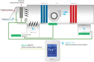
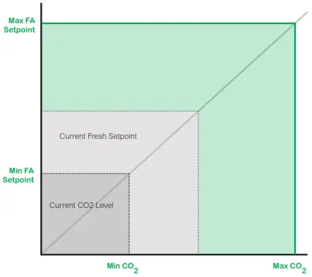
ECONOMIZER CONTROL MODE AND CO2 LEVEL CONTROL
If the fresh air damper is to be used for both free cooling and CO2 level control (economizer mode and CO2 level control, but without fresh air measurement station), only the Min Pos, Max Pos, Min CO2, and Max CO2 parameters, as well as the free cooling sequence, will be active.
• The FA Range parameter should be set to 0 CFM.
• Set AI1 parameter to CO2 (0 VDC = 0ppm ; 10VDC = 2000ppm)
• Min Pos, Max Pos, Min CO2, and Max CO2 parameters should be set according to the required setting.
The highest value between free cooling demand output and interpolation output for the fresh air setpoint will be the output to the fresh air damper.
ECONOMIZER CONTROL MODE, CO2 LEVEL CONTROL AND FRESH AIR MEASUREMENT STATION
If the fresh air damper is to be used for both free cooling and CO2 level control with a fresh air measurement station, only the Min FA, Max FA, Min CO2, and Max CO2 parameters, as well as the free cooling sequence, will be active.
- The FA Range parameter should be set to something other than 0 CFM.
- Use an airflow transmitter to read fresh air level with AI2 input (0-5 VDC input)
- Min FA, Max FA, Min CO2, and Max CO2 parameters should be set according to the required setting.
The highest value between free cooling demand output and interpolation output for the fresh air setpoint based on the CO2 level will be the output to the fresh air damper.
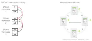
APPENDIX A. OPTIONAL NETWORK SET-UP
Notes:
• Wiring should be daisy-chained
• Respect polarity
• If using 2 conductors shielded wires, connect the shield of each feed together on the back of the controller. ONLY ground the shield at one location. DO NOT connect the shield to the ref terminal.
APPENDIX B. WIRELESS SENSORS
WIRELESS ZIGBEE® PRO MOTION SENSORS
Room Controllers with SED Series ZigBee ® Pro wireless switches can be used in stand-alone mode, or with integration to a central management system, to allow for advanced functions such as central reservation and occupancy functions. Up to twenty different ZigBee motion sensors and switches (SED-WDC, SED-WMS, SED-MTH, or SED-WLS) can be used with a Room ControllerNote that if a ZigBee wireless window switch is used, the Room Controller cannot also use a remote PIR motion sensor, whether wired or wireless. Using one or more wireless remote PIR motion sensors means that a wired PIR motion sensor cannot be used, and vice versa. The SED Series sensors are factory delivered with batteries and are ready to be installed, configured, and used right out of the box. Due to the extremely small current consumption of the sensors, the expected battery life is approximately 10 years, which is equivalent to the battery shelf life.
MODEL SELECTION
| Window Switch | Door Switch |
| Wireless Window/door sensor | SED-WDC-G-5045 |
| Wireless wall-mounted motion sensor | SED-WMS-P-5045 |
| Wireless motion/temperature/humidity sensor | SED-MTH-G-5045 |
| Wireless water leakage sensor | SED-WLS-G-5045 |
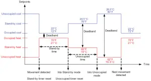
APPENDIX C. SCHEMATIC OF CONTROLLERS OCCUPANCY SEQUENCE OF OPERATION WITHOUT DOOR SENSOR
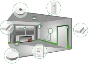
APPENDIX D. DEPLOYMENT
The placement of the Room Controller must be given consideration. It is recommended to install the Room Controller as close to a door as possible (but not so as to be blocked by the door), or in an area with high occupant movement. Ideally, the Room Controller should be installed 5 feet (1.5 meters) above the floor surface to ensure maximum detection range is achieved. As well, Room Controller placement should ensure the occupant crosses the lens beam in a perpendicular path within the prescribed detection zone.
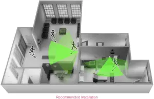
EXAMPLE OF RECOMMENDED DEPLOYMENT
The below shows Room Controllers installed in ideal locations for two rooms. The examination room shows one Room Controller installed adjacent to the door. In this area of the room, occupant traffic is high and ensures the occupant will almost always cross the PIR detection path laterally and within the detection range. The waiting room shows one Room Controller installed beside a door in the middle of the room. As shown in the diagram below, occupant traffic is high in several areas of the room including the entrance, waiting room, access to the door, and activity around the reception desk. Moreover, for each case aforementioned, occupant movement almost always moves lateral to the PIR, which ensures detection by the PIR, as well as respecting the PIR detection range of 20 feet (6 meters) at 140°, and 16 feet (5 meters) between 15° to 30° laterally.
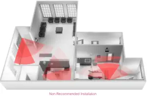
EXAMPLE OF NON-RECOMMENDED DEPLOYMENT
The below shows four Room Controllers (two for each room) installed in non-ideal locations for the two rooms. The examination room shows one Room Controller installed in a low traffic area near the door, and a second Room Controller installed on the wall directly opposite the door. For the Room Controller installed in the corner wall, the PIR could be blocked by the opened door, while occupant traffic cold also is minimal in this area of the room. For the second Room Controller installed opposite the door, the PIR detection could fall outside the specified detection zone, while at the same time most occupant movement would not be lateral to the PIR, thereby not respecting optimal crossing patterns for PIR detection. The waiting room shows one Room Controller installed in the corner of the room, and a second Room Controller installed beside the reception area. For the Room Controller installed in the corner, the opening/closing of the door creates a high probability that the PIR would get blocked, and therefore, occupancy going undetected. For the Room Controller installed beside the reception area, occupant traffic could fall outside the detection zone, and the receptionist would often be below the 5 foot recommended installation height for the Room Controller.
ROOM CONTROLLER PIR SENSOR DETAILS
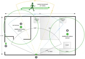
RECOMMENDATIONS FOR INSTALLATIONS
- Install the Room Controller to cover the more lateral movement.
- Install a door sensor, the internal Room Controller occupancy logic works better with a door sensor. Once a motion is detected
after a door is opened, the room stays in an occupied state until the door is opened again which puts the Room Controller in standby mode, and if there is a motion then it goes back in occupied mode. It is also recommended to disable the unoccupied mode, set the unoccupied time to 0, so there are only 2 modes in the Room Controller: stand-by and occupied for a stand-alone solution. Please refer to the two(2) diagrams below for the Room Controller internal occupancy states transition.  Install additional motion sensors in the bathroom.
- Install additional motion sensors for better motion detection in the entire room.
 Install additional motion sensors in the bathroom.
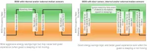
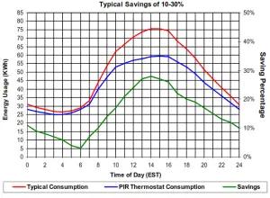
ENERGY SAVINGS
PIR can maximize your energy saving from 10-30% by adjusting temperature set points in unoccupied zones during scheduled periods.
PIR can maximize your energy saving from 10-30% by adjusting temperature set points in unoccupied zones during scheduled periods.
 APPENDIX E. TERMINAL CORRESPONDENCE
 APPENDIX E. TERMINAL CORRESPONDENCE
The terminals of a VT8650 are identified differently and have a wider range of possible functions compared to those of any of the VT7000 Room Controllers. Nonetheless, there is a direct correspondence of functions between the terminals of the VT7000 and the VT8650. Consult the table below to verify the appropriate term when replacing a T7000 Room Controller with a VT8650 Room Controller.
| VT7000 | VT8650 | ||
| Terminal name | Terminal ID | Terminal ID | |
| Binary Input 1 | BI1 | Terminal name | UI16 |
| Binary Input 2 | BI2 | Universal Input 16 | UI17 |
| Universal Input 3 | UI3 | Universal Input 19 | UI19 |
| Sensor Common | Scam | Terminal 18 Common | COM |
| Remote Sensor | RS | Universal Input 20 | UI20 – RS |
| Sensor Common | Scam | Terminal 21 Common | COM |
| Mix/Supply Sensor | MS | Universal Input 22 | UI22 – SS |
![]()


