Integral Bolster or Fullering Attachment
Integral Bolster/ Fullering Attachment
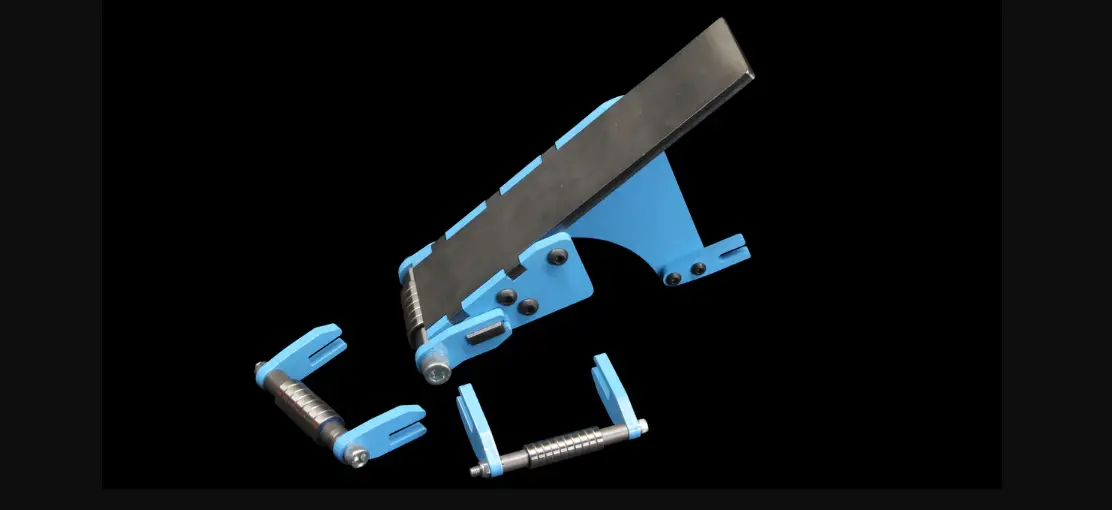
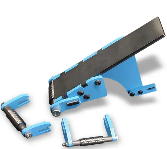
The Integral Bolster/ Fullering Attachment is a component that can be attached to a compatible machine to allow for bolstering and fullering of metal objects. The attachment is comprised of several parts listed in the parts list below. The assembly instructions for the attachment are also provided below.
Parts List:
| ITEM | DESCRIPTION | QTY | IMAGE |
|---|---|---|---|
| 1 | BASE | 1 | |
| 2 | INTEGRAL ATTACHMENT BRACE | 1 | |
| 3 | INTEGRAL ATTACHMENT SIDE PLATE | 1 | |
| 4 | INTEGRAL ATTACHMENT PLATEN | 1 | |
| 5 | QUICK CHANGE TAB | 2 | |
| 6 | 1/4 BUTTON HEAD SCREW 5/8 LG | 4 | |
| 7 | 1/4 THIN NYLOCK NUT | 1 | |
| 8 | 3/8 THIN NYLOCK NUT | 1 | |
| 9 | 1/4 ID X 5/8 OD BEARING | 9 | |
| 10 | 1/2 ID BEARING BRACKET | 2 | |
| 11 | 3/8 ID BEARING BRACKET | 2 | |
| 12 | 1/4 ID BEARING BRACKET | 2 | |
| 13 | 5/16 BUTTON HEAD SCREW 4.0 LG | 3 | |
| 14 | 5/16 THIN NYLOCK NUT | 3 | |
| 15 | 3/8 ID X 7/8 OD BEARING | 7 | |
| 16 | 1/2 ID X 1-1/8 OD BEARING | 6 | |
| 17 | 1/4 SOCKET HEAD SCREW 4-1/2 LG | 1 | |
| 18 | 3/8 SOCKET HEAD SCREW 4-1/2 LG | 1 | |
| 19 | 1/2 SOCKET HEAD SCREW 4-1/2 LG | 1 | |
| 20 | 1/2 ID BEARING SPACER | 2 | |
| 21 | 3/8 ID BEARING SPACER | 2 | |
| 22 | 1/4 ID BEARING SPACER | 2 |
Integral Bolster/ Fullering Attachment Assembly Instructions:
- Attach the Integral Attachment Brace (2) to the Base (1) using four 1/4 Button Head Screws (6) and 1/4 Thin Nylock Nuts (7).
- Attach the Integral Attachment Side Plate (3) to the Base (1) using two Quick Change Tabs (5), two 1/4 Button Head Screws (6), and two 1/4 Thin Nylock Nuts (7).
- Insert the Platen (4) into the Integral Attachment Side Plate (3) and secure using two 5/16 Button Head Screws (13) and two 5/16 Thin Nylock Nuts (14).
- Attach the Integral Attachment (1) to the Integral Attachment Brace (2) and Integral Attachment Side Plate (3) using two 1/2 ID Bearing Brackets (10), two 3/8 ID Bearing Brackets (11), and two 1/4 ID Bearing Brackets (12).
- Insert one 3/8 ID X 7/8 OD Bearing (15) into each of the two 3/8 ID Bearing Brackets (11).
- Insert one 1/2 ID X 1-1/8 OD Bearing (16) into each of the two 1/2 ID Bearing Brackets (10).
- Insert one 1/4 ID X 5/8 OD Bearing (9) into each of the four Platen holes.
- Insert one 1/2 ID Bearing Spacer (21) into each of the two 1/2 ID Bearing Brackets (10).
- Insert one 3/8 ID Bearing Spacer (22) into each of the two 3/8 ID Bearing Brackets (11).
- Insert one 1/4 ID Bearing Spacer (23) into each of the two 1/4 ID Bearing Brackets (12).
- Insert 3/8-16 X 4.5 Socket Head Bolt through the Bearing Holder into the Spacer, Bearings (8), Spacer, and Bearing Holder. Install the 3/8-16 Lock Nut. Tighten by hand until there is no space between the bearings and the bearings still spin without resistance.
Product Usage Instructions
The Integral Bolster/ Fullering Attachment should only be used with a compatible machine as specified in the user manual. The attachment can be used to bolster and fuller metal objects. Please follow all safety guidelines and instructions provided in the user manual before using the attachment.
Contact Brodbeck Ironworks LLC for any questions or concerns before operating this equipment
IF YOU HAVE ANY ISSUES WITH ASSEMBLY OR MISSING PARTS PLEASE CONTACT US IMMEDIATELY
Ben Secrist513-532-7062, [email protected]
| ITEM DESCRIPTION QTY IMAGE | |||
| 1 | INTEGRAL ATTACHMENT BASE | 1 |  |
| 2 | INTEGRAL ATTACHMENT BRACE | 1 |  |
| 3 | INTEGRAL ATTACHMENT SIDE PLATE | 1 | 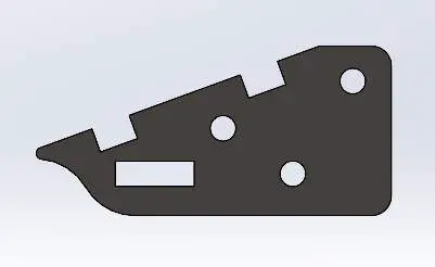 |
| 4 | INTEGRAL ATTACHMENT PLATEN | 1 |  |
| 5 | QUICK CHANGE TAB | 2 |  |
| 6 | 1/4” BUTTON HEAD SCREW 5/8” LG | 4 |  |
| 7 | 1/4” THIN NYLOCK NUT | 1 | 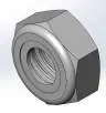 |
| 8 | 3/8” THIN NYLOCK NUT | 1 | |
| 9 | ½” THIN NYLOCK NUT | 1 | 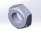 |
| 10 | 1/2” ID BEARING BRACKET | 2 | 
|
| 11 | 3/8” ID BEARING BRACKET | 2 | 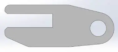 |
| 12 | 1/4” ID BEARING BRACKET | 2 |  |
| 13 | 5/16” BUTTON HEAD SCREW 4.0” LG | 3 |  |
| 14 | 5/16” THIN NYLOCK NUT | 3 | |
| 15 | 1/4” ID X 5/8” OD BEARING | 9 |  |
| 16 | 3/8” ID X 7/8” OD BEARING | 7 | 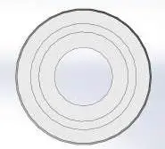 |
| 17 | 1/2” ID X 1-1/8” OD BEARING | 6 | 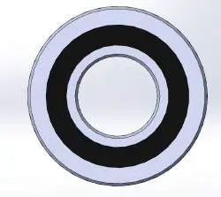 |
| 18 | 1/4” SOCKET HEAD SCREW 4-1/2” LG | 1 | 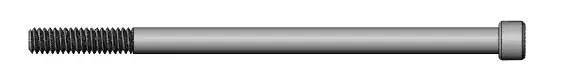 |
| 19 | 3/8” SOCKET HEAD SCREW 4-1/2” LG | 1 | 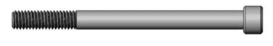 |
| 20 | 1/2” SOCKET HEAD SCREW 4-1/2” LG |
1 | 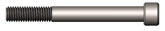 |
| 21 | 1/2” ID BEARING SPACER | 2 | 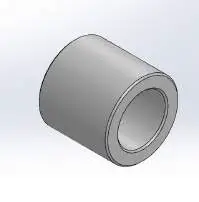 |
| 22 | 3/8” ID BEARING SPACER | 2 | |
| 23 | 1/4” ID BEARING SPACER | 2 | 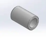 |
TOOL LIST
- 3/4” COMBO WRENCH
- 9/16” COMBO WRENCH
- 7/16” COMBO WRENCH
- 1/2” COMBO WRENCH
- 3/8” HEX KEY (ALLEN WRENCH)
- 5/16” HEX KEY (ALLEN WRENCH)
- 3/16” HEX KEY (ALLEN WRENCH)
- 5/32” HEX KEY (ALLEN WRENCH)
INTEGRAL ATTACHMENT ASSEMBLY
BEARING SETS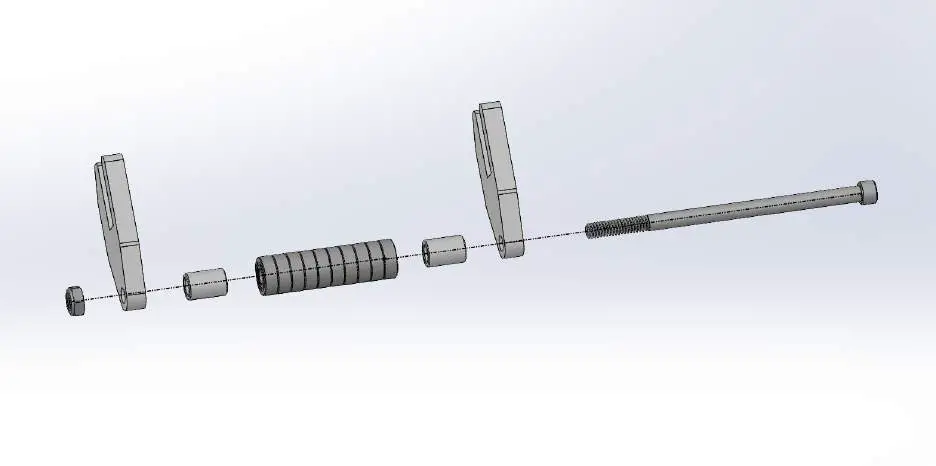
- Insert ½-13 x 4.5” socket head bolt through the bearing holder into the spacer, bearings(7), spacer, and bearing holder. Install the ½-13 lock nut. Tighten by hand until
there is no space between the bearings and the bearings still spin without resistance. - Insert 3/8-16 x 4.5” socket head bolt through the bearing holder into the spacer, bearings(8), spacer, and bearing holder. Install the 3/8-16 lock nut. Tighten by hand until there is no space between the bearings and the bearings still spin without resistance.
- Insert ¼-20 x 4.5” socket head bolt through the bearing holder into the spacer, bearings(11), spacer, and bearing holder. Install the ¼-20 lock nut. Tighten by hand until there is no space between the bearings and the bearings still spin without resistance.
INTEGRAL ATTACHMENT
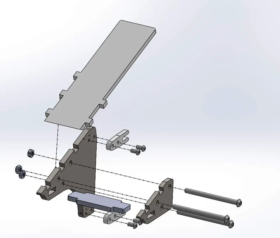
- Install the ¼-20 Round Head Screws through the QC Offset Brackets into the IAT Base.
- Insert the IAT Brace into the IAT Base. Install the IAT Side Plate onto the IAT Brace.
- Assemble the IAT Platen tabs into the slots of the IAT Side Plate and the IAT Base.
- Insert the 5/16-18 x 4.0 button head screws through the IAT Side Plate into the base.
- Install the 5/16 – 18 lock nut with washer to the bolts and hand tighten
If your assembly came with an arm and Quick Change Assembly, the instructions can be found on our website. www.brodbeckironworks.com


