![]()
CONTROLLERS
EU-295 v2, v3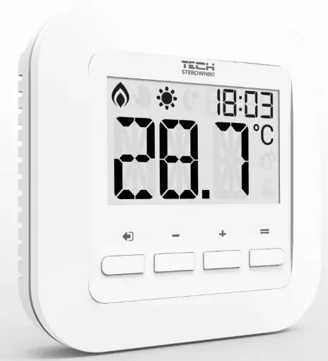
User Manual
KN.20.04.01
SAFETY
Before using the device for the first time the user should read the following regulations carefully. Not obeying the rules included in this manual may lead to personal injuries or controller damage. The user’s manual should be stored in a safe place for further reference. In order to avoid accidents and errors it should be ensured that every person using the device has familiarized themselves with the principle of operation as well as security functions of the controller. If the device is to be sold or put in a different place, make sure that the user’s manual is there with the device so that any potential user has access to essential information about the device.
The manufacturer does not accept responsibility for any injuries or damage resulting from negligence; therefore, users are obliged to take the necessary safety measures listed in this manual to protect their lives and property.![]() WARNING
WARNING
- High voltage! Make sure the regulator is disconnected from the mains before performing any activities involving the power supply (plugging cables, installing the device etc.).
- The device should be installed by a qualified electrician.
- The regulator should not be operated by children.
![]() WARNING
WARNING
- The device may be damaged if struck by a lightning. Make sure the plug is disconnected from the power supply during storm.
- Any use other than specified by the manufacturer is forbidden.
- Before and during the heating season, the controller should be checked for condition of its cables. The user should also check if the controller is properly mounted and clean it if dusty or dirty.
Changes in the merchandise described in the manual may have been introduced subsequent to its completion on April 1th 2020. The manufacturer retains the right to introduce changes to the structure. The illustrations may include additional equipment. Print technology may result in differences in colours shown.![]() Care for the natural environment is our priority. Being aware of the fact that we manufactureelectronic devices obligates us to dispose of used elements and electronic equipment in a manner which is safe for nature. As a result, the company has received a registry number assigned by the Main Inspector of Environmental Protection. The symbol of a crossed outrubbish bin on a product means that the product must not be thrown out to ordinary waste bins. By segregating waste intended for recycling, we help protect the natural environment. It is the user’s responsibility to transfer waste electrical and electronic equipment to the selected collection point for recycling of waste generated from electronic and electrical equipment.
Care for the natural environment is our priority. Being aware of the fact that we manufactureelectronic devices obligates us to dispose of used elements and electronic equipment in a manner which is safe for nature. As a result, the company has received a registry number assigned by the Main Inspector of Environmental Protection. The symbol of a crossed outrubbish bin on a product means that the product must not be thrown out to ordinary waste bins. By segregating waste intended for recycling, we help protect the natural environment. It is the user’s responsibility to transfer waste electrical and electronic equipment to the selected collection point for recycling of waste generated from electronic and electrical equipment.
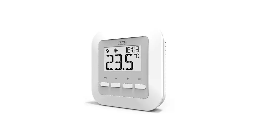
DEVICE DESCRIPTION
EU-295 room regulator is intended for controlling thermoactuators. Its main task is to maintain the pre-set room temperature by sending a signal to the actuator (contact closing) when the room temperature is too low.
EU-295 regulator functions:
- Maintaining pre-set room temperature
- Manual mode
- Day/night mode
Controller equipment:
- Built-in temperature sensor
- Batteries
- Possibility of connecting a floor sensor
- Possibility of pairing with MW-1 (v2 version)
INSTALLATION
The controller should be installed by a qualified person. EU-295 controller may be installed on the wall.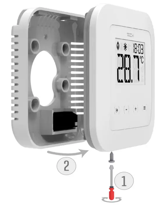
The room regulator should be connected to the heating device using a two-core cable, as illustrated below: EU-295v2 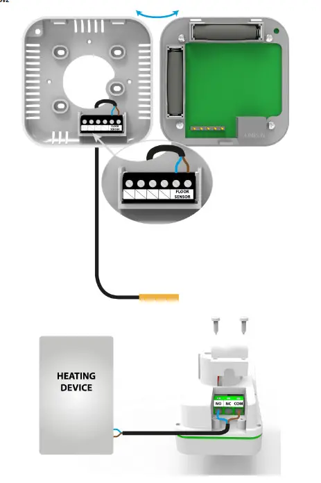
![]() NOTE The marking on the back of the controller refers to the built-in transmitter. It does not refer to the type of actuator connected.
NOTE The marking on the back of the controller refers to the built-in transmitter. It does not refer to the type of actuator connected.![]() NOTE The regulator is powered with batteries, which should be periodically checked and replaced at least once every heating season. In order for the control circuit to operate properly, it is necessary to provide the regulator with 230 V AC power supply, as illustrated in the diagram.
NOTE The regulator is powered with batteries, which should be periodically checked and replaced at least once every heating season. In order for the control circuit to operate properly, it is necessary to provide the regulator with 230 V AC power supply, as illustrated in the diagram.
FIRST START-UP
Follow these step while starting the controller for the first time to ensure proper operation:
- Remove the front cover and insert the batteries.
- Connect the regulator to the actuator as illustrated in the diagram.
HOW TO USE THE CONTROLLER
- PRINCIPLE OF OPERATI ON
The main task of ST-295 is to maintain the pre-set room/floor temperature by sending a signal to the heating device (contact closing) or to the external controller managing the actuators, when the room/floor temperature is too low. When such a signal is received, the heating device opens the flow in the thermostatic valve. - OPERATION MODES
The regulator may operate in one of the two operation modes available:
Day/night mode – in this mode the pre-set temperature changes depending on the time of the day. The user presets the temperature values for both day-time and night-time as well as the time of entering day mode and night mode. In order to activate this mode, press EXIT and hold until a corresponding icon (day/night mode) appears on the main screen.
Manual mode – In this mode, the user sets the temperature in the main screen view using PLUS and MINUS buttons. The manual mode will be activated automatically after pressing one of these buttons. Once this mode is activated, the previously selected mode enters ‘sleep mode’ and remains inactive until the next preprogrammed temperature change.
The manual mode may be deactivated by pressing EXIT button.
MAIN SCREEN DESCRIPTION
The user navigates in the menu structure using buttons.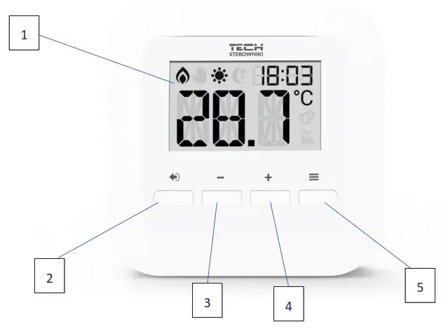
- Display
- EXIT – pressing this button in the main screen view activates day/night mode. After entering the menu, this button is used to confirm the settings and return to the main screen view.
- MINUS button – pressing this button in the main screen view activates manual mode and decreases the pre-set temperature. After entering the menu, this button is used to adjust parameters.
- PLUS button – pressing this button in the main screen view activates manual mode and increases the pre-set temperature. After entering the menu, this button is used to adjust parameters.
- MENU button – hold this button in order to enter the controller menu. While editing parameters press this button to confirm the changes and move on to edit the next parameter.
![]() NOTE
NOTE
Press and hold MENU button for 2 seconds to see the floor temperature displayed on the screen. Press MENU button again to check the battery level. Press the button again to check the software version. 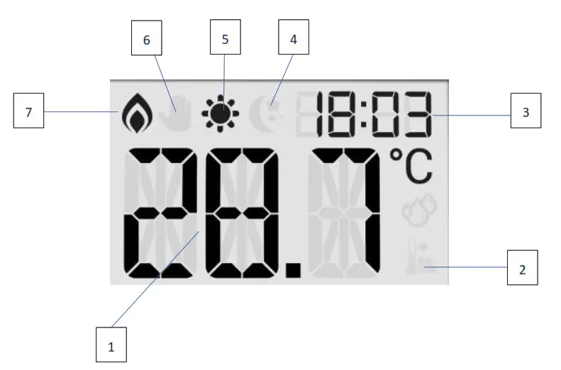
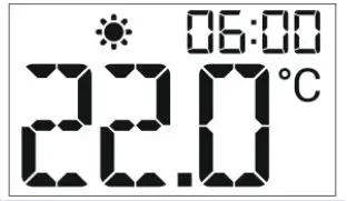
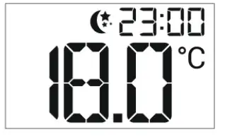
- Current temperature
- Floor heating active
- Current time
- Night mode active
- Day mode active
- Manual mode active
- Heating to pre-set temperature active
CONTROLLER FUNCTIONS
Use touch buttons PLUS, MINUS, EXIT and MENU to navigate through the menu structure. In order to edit a given parameter, press MENU. Use MENU button to view further options – the icon of the edited parameter is flashing, the remaining icons are blank. In order to change the settings, use PLUS and MINUS buttons. Once a change has been introduced, confirm by pressing MENU button (confirm and move on to edit the next parameter) or EXIT button (confirm and return to the main screen view).
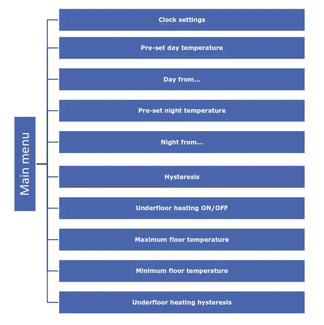
- BLOCK DIAGRAM OF MAI N MENU

- CLOCK SETTINGS
In order to set the time, enter the menu and press MENU button until the clock settings appear on the screen. Use PLUS and MINUS to set the hour and minutes. Confirm by pressing MENU button (confirm and move on to edit the next parameter) or EXIT button (confirm and return to the main screen view).
- PRE-SET DAY TEMPERATURE
In order to define the pre-set day temperature, enter the menu and press MENU button until the pre-set day temperature settings appear on the screen. Use PLUS and MINUS to set the temperature. Confirm by pressing MENU button (confirm and move on to edit the next parameter) or EXIT button (confirm and return to the main screen view).
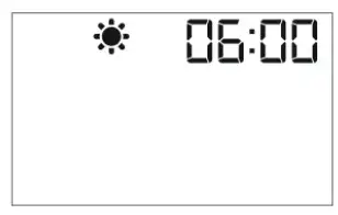
- DAY FROM…
This function enables the user to define the exact time of entering the day mode. To configure this parameter, press MENU until Day from… settings appear on the screen. Use PLUS and MINUS to set the hour and minute of day mode activation. Confirm by pressing MENU button (confirm and move on to edit the next parameter) or EXIT button (confirm and return to the main screen view).
- PRE-SET NIGHT TEMPERATURE
In order to define the pre-set night temperature, enter the menu and press MENU button until the pre-set night temperature settings appear on the screen. Use PLUS and MINUS to set the temperature. Confirm by pressing MENU button (confirm and move on to edit the next parameter) or EXIT button (confirm and return to the main screen view).
- NIGHT FROM…
This function enables the user to define the exact time of entering the night mode. To configure this parameter, press MENU until Night from… settings appear on the screen. Use PLUS and MINUS to set the hour and minute of night mode activation. Confirm by pressing MENU button (confirm and move on to edit the next parameter) or EXIT button (confirm and return to the main screen view).
- PRE-SET TEMPERATURE HYSTERESIS
Room temperature hysteresis defines the pre-set temperature tolerancein order to prevent undesired oscillation in case of small temperaturefluctuation (within the range of 0,2 ÷ 5°C). Example:
Pre-set temperature: 23°C
Histeresis: 1°C
The room regulator reports that the temperature is too low when the room temperature drops to 22 °C.
In order to set the hysteresis, press MENU until the hysteresis settings appear on the screen.
Use PLUS and MINUS to set the desired hysteresis value. Press MENU to confirm and move on to the next parameter or press EXIT to confirm and return to the main screen view. - UNDERFLOOR HEATING O N/OFF
In order to enable or disable underfloor heating, press MENU until underfloor heating settings appear on the screen.
To activate the underfloor heating, press PLUS. Confirm by pressing MENU button (confirm and move on to edit the next parameter) or EXIT button (confirm and return to the main screen view). To deactivate the underfloor heating, press MINUS. Confirm by pressing MENU button (confirm and move on to edit the next parameter) or EXIT button (confirm and return to the main screen view).
 - MAXIMUM FLOOR TEMPERAT URE
In order to set the maximum floor temperature, activate the underfloor heating (section 8) and press MENU until the maximum floor temperature settings appear on the screen. Use PLUS and MINUS to set the temperature. Confirm by pressing MENU button (confirm and move on to edit the next parameter) or EXIT button (confirm and return to the main screen view).
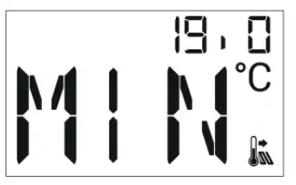
- MINIMUM FLOOR TEMPERATURE
In order to set the minimum floor temperature, activate the underfloor heating (section 8) and press MENU until the minimum floor temperature settings appear on the screen. Use PLUS and MINUS to set the temperature. Confirm by pressing MENU button (confirm and move on to edit the next parameter) or EXIT button (confirm and return to the main screen view).
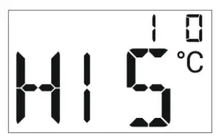
- UNDERFLOOR HEATING H YSTERESIS
Underfloor heating hysteresis defines the tolerance for the maximum and minimum temperature. The settings range is 0,2°C to 5 °C.
If the floor temperature exceeds the maximum temperature, the underfloor heating will be disabled. It will be enabled only after the temperature has dropped below the maximum floor temperature minus hysteresis value.
 Example:
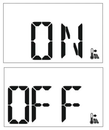 To deactivate the underfloor heating, press MINUS. Confirm by pressing MENU button (confirm and move on to edit the next parameter) or EXIT button (confirm and return to the main screen view).
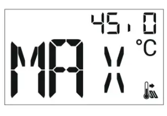
Example:
Maximum floor temperature – 33°C
Hysteresis – 2°C
When the floor temperature reaches 33°C, the underfloor heating will be disabled. It will be activated again when the temperature drops to 31°C.
If the floor temperature drops below the minimum temperature, the underfloor heating will be enabled. It will be disabled after the floor temperature has reached the minimum value plus hysteresis value.
Example:
Minimum floor temperature – 23°C
Hysteresis – 2°C
When the floor temperature drops to 23°C, the underfloor heating will be enabled. It will be disabled when the temperature reaches 25°C.
TECHNICAL DATA
| Specification | Value |
| Range of room temperature setting | 5ºC ÷ 35ºC |
| Supply voltage | Baterie 2xAAA 1,5V |
| Accuracy of room temperature measurement | +/- 0,5ºC |
| Potential-free cont. nom. out. Load (EU-295v3) | 230V AC / 0,5A (AC1) * 24V DC / 0,5A (DC1) ** |
| Operating temperature | 5ºC ÷ 50ºC |
| Frequency (EU-295v2) | 868MHz |
* AC1 load category: single-phase, resistive or slightly inductive AC load.
** DC1 load category: direct current, resistive or slightly inductive load.
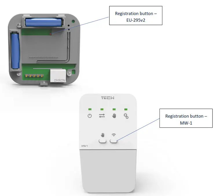
HOW TO REGISTER EU-295 V2
In order to register EU-295v2, follow these steps:
- Press Registration button in MW-1;
- Press and hold Registration button in EU-295v2 for 5 seconds.
![]() NOTE
NOTE
Once registration has been activated in MW-1, it is necessary to press the registration button in EU-295v2 controller within 2 minutes. When the time is over, the pairing attempt will fail.
If:
- EU-295v2 screen shows SCS and all the control lights in MW-1 are flashing simultaneously – the registration has been successful.
- the control lights in MW-1 are flashing one after another from one side to the other – MW-1 module has not received the signal from the main controller
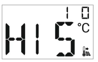
- EU-295v2 screen displays ERR and all the control lights in MW-1 light up continuously – the registration attempt failed.
![]() CONTROLLERS
CONTROLLERS
EU Declaration of Conformity
Hereby, we declare under our sole responsibility that EU-295v2 manufactured by TECH STEROWNIKI, head-quartered in Wieprz Biała Droga 31, 34-122 Wieprz, is compliant with Directive 2014/53/EU of the European parliament and of the Council of 16 April 2014 on the harmonisation of the laws of the Member States relating to the making available on the market of radio equipment, Directive 2009/125/EC establishing a framework for the setting of ecodesign requirements for energy-related products as well as the regulation by the MINISTRY OF ENTREPRENEURSHIP AND TECHNOLOGY of 24 June 2019 amending the regulation concerning the essential requirements as regards the restriction of the use of certain hazardous substances in electrical and electronic equipment, implementing provisions of Directive (EU) 2017/2102 of the European Parliament and of the Council of 15 November 2017 amending Directive 2011/65/EU on the restriction of the use of certain hazardous substances in electrical and electronic equipment (OJ L 305, 21.11.2017, p. 8).
For compliance assessment, harmonized standards were used:
PN-EN IEC 60730-2-9 :2019-06 art. 3.1a Safety of use
ETSI EN 301 489-1 V2.2.3 (2019-11) art.3.1b Electromagnetic compatibility
ETSI EN 301 489-3 V2.1.1:2019-03 art.3.1 b Electromagnetic compatibility
ETSI EN 300 220-2 V3.2.1 (2018-06) art.3.2 Effective and coherent use of radio spectrum
ETSI EN 300 220-1 V3.1.1 (2017-02) art.3.2 Effective and coherent use of radio spectrum
Hereby, we declare under our sole responsibility that EU-295v3 manufactured by TECH STEROWNIKI, head-quartered in Wieprz Biała Droga 31, 34-122 Wieprz, is compliant with Directive 2014/35/EU of the European Parliament and of the Council of 26 February 2014 on the harmonisation of the laws of Member States relating to the making available on the market of electrical equipment designed for use within certain voltage limits (EU OJ L 96, of 29.03.2014, p. 357), Directive 2014/30/EU of the European Parliament and of the Council of 26 February 2014 on the harmonisation of the laws of Member States relating to electromagnetic compatibility (EU OJ L 96 of 29.03.2014, p.79), Directive 2009/125/EC establishing a framework for the setting of ecodesign requirements for energy-related products as well as the regulation by the MINISTRY OF ENTREPRENEURSHIP AND TECHNOLOGY of 24 June 2019 amending the regulation concerning the essential requirements as regards the restriction of the use of certain hazardous substances in electrical and electronic equipment, implementing provisions of Directive (EU) 2017/2102 of the European Parliament and of the Council of 15 November 2017 amending Directive 2011/65/EU on the restriction of the use of certain hazardous substances in electrical and electronic equipment (OJ L 305, 21.11.2017, p. 8).
For compliance assessment, harmonized standards were used: PN-EN IEC 60730-2-9:2019-06, PN-EN 60730-1:2016-10.
Wieprz, 01.04.2020
Central headquarters: ul. Biala Droga 31, 34-122 Wieprz
Service: ul. Skotnica 120, 32-652 Bulowice
phone: +48 33 875 93 80
e-mail: [email protected]
www.tech-controllers.com


