![]() Z-TRM3
Z-TRM3
Firmware 4.0
01.03.20
Ver 2020-C
Installers manual 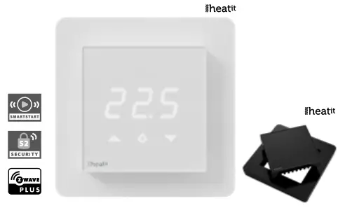
INTRODUCTION
Heatit Z-TRM3 is an electronic thermostat for electrical floor heating, designed to be mounted in a standard flush box. The thermostat has a built-in Z-Wave chip that can be connected with Home Automation systems. Heatit Z-TRM3 is equipped with a single-pole relay and fits into System 55 frames. The thermostat can withstand a load of max
16A /3600W at 230V. The thermostat may be used for water-based heating if the thermostat is linked to the Heatit Z-Water.
NB! If the sensor mode is changed to A or AF mode then a room sensor compensation process will start, which limits maximum power output to 75%. The thermostat adapts to the environment within a few days. No internal sensor calibration should be performed during the first few days.
STATEMENT REGARDING PRODUCTS FROM MULTIPLE MANUFACTURERS
Please read this before installation
This device may be used with all devices certified with the Z-Wave Plus™ certificate and should be compatible with such devices produced by other manufacturers. Every primary controller is different depending on the manufacturer, their target consumer, and intended use/application.
Please review the functionalities implemented by the primary controller you intend to use with our Z-Wave Plus certified device to ensure that it provides the necessary controls to take full advantage of our product’s capabilities.
BEHAVIOR WITHIN THE Z-WAVE NETWORK
This device may be operated within any Z-Wave network with Z-Wave-certified devices from other manufacturers. All non-battery-operated nodes within the network will act as repeaters regardless of the manufacturer to increase the reliability of the network. On delivery, the device does not belong to any Z-Wave network. The device needs to be added to an existing network to communicate with the other devices within it. Devices may also be removed from a network. The add/remove processes are initiated by the primary controller of the Z-Wave network.
The primary controller has a mode for adding or removing devices.
Please refer to your primary controller manual on how to set the primary controller in add/remove mode. The device may only be added or removed from the network if the primary controller is in add/remove mode.
QUICK START
- Switch off the mains supply (disable the fuse).
- Open the wall switch box.
- Connect wires according to the labeling described in chapter 5 ”Installation”.
- After verifying the connections, switch the main supply back on.
- Set the primary controller in add mode (security/non-security).
- Press and hold the center button until “OFF” is shown on the display (approx. 10 seconds).
- Press the down button until you reach “CON”, press and hold until the display shows a rotating light pattern.
- The thermostat will display “INC” when the thermostat is successfully added.
NB! If adding/removing fails, Err (error) will appear.
INSTALLATION
Installation must be done by a qualified electrician in accordance with the National Building codes. Before installation, disconnect any power to the thermostat mains. During the installation of the thermostat, power to the thermostat must be disconnected AT ALL TIMES!
 CONTROLS
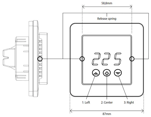
Use e.g. a small slotted screwdriver. Start by carefully removing the front cover by pushing the release springs. The front cover and the frame may now be removed.
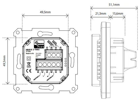
 Connect the wires to the thermostat terminals: Use 1,5mm² or 2,5mm² according to load.
HEATING (N) Heating cable connection (Neutral)
N Power connection (Neutral) 230V
L Power connection (Live) 230V
HEATING (L) Heating cable connection
FLOOR SENSOR NTC type (10, 12, 15, 22, 33, or 47kΩ) Default 10kΩ
EXTERNAL SENSOR NTC type (10, 12, 15, 22, 33 or 47kΩ) Default 10kΩ
Next, position the thermostat and mount it into the wall flush box using 2-4 screws. Position the frame over the flush box, then position and carefully press the front cover until it snaps in place. Check that the front cover has snapped in place properly on both sides. The front cover should now fit firmly on all sides. In order to read the PowerMetering, the load needs to be connected to both heating L + N.
NOTE! The top cover has to be installed when the thermostat is connected to the main power source. The thermostat is not a SELV product. All voltage parts must be considered to be 230VAC.
ADD/REMOVE
The primary controller/gateway has a mode for adding or removing devices. Please refer to your primary controller manual on how to set the primary controller in add/remove mode. The device may only be added or removed from the network if the primary controller is in add/remove mode. When the device is removed from the network, it will NOT revert to factory settings.
There are two ways to add the Heatit Z-TRM3 to a Z-Wave network.
METHOD 1: STANDARD (MANUAL)
- Press Center (confirm) for 10 seconds. The display will show OFF.
- Press Right (down) 5 times until you see Con on the display.
- Start the add/remove device process in your primary controller.
- Start the add/remove mode in the Heatit Z-TRM3 by pressing Center (confirm) for approximately 2 seconds.
Adding/removing mode is indicated on the display by rotating LED segments on the display. This lasts until the timeout occurs after 90 seconds, or until the module has been added/removed in the network. Confirmation will show Inc/EcL on the display. Exit programming mode by choosing ESC in the menu. Your thermostat is now ready for use with default settings.
NB! When the thermostat is removed from the gateway, the parameters are not reset. To reset the parameters, see Chapter 7: ”Factory reset”. If adding/removing fails, Err (error) will appear. Please perform a ”remove device” process and try again. If Err displays again, please see Chapter 7: “Factory reset”.
METHOD 2: SMARTSTART (AUTOMATIC)
SmartStart-enabled products can be added to a Z-Wave network by scanning the Z-Wave QR-Code present on the product with a controller providing SmartStart inclusion. No further action is required and the SmartStart product will be added automatically within 10 minutes of being switched on in the network vicinity.
The Z-Wave QR-Code locations may be found in Chapter 20 ”Z-Wave QR-Code/DSK”.
FACTORY RESET
By pressing buttons Right and Center (down and confirm) for 20 seconds, the thermostat will perform a complete factory reset.
NB! Please use this procedure only when the primary controller/ gateway is missing or otherwise inoperable.
The device will display rES for 10 seconds while performing a factory reset.
When rES no longer is displayed, the thermostat has been reset.
STARTUP
AFTER POWERING UP THE THERMOSTAT FOR THE FIRST TIME, ALL PARAMETERS WILL HAVE DEFAULT SETTINGS.
PRINCIPLES OF REGULATION
Using Floor / External sensor (F, A2 or A2F-Mode)
The thermostat uses temperature readings retrieved from the internal sensor or external wired sensor to regulate heating. When you have chosen a setpoint temperature, the thermostat will use an internal hysteresis to regulate the temperature. This hysteresis is adjustable.
See Chapter 5 “Installation”.
Using Internal sensor (A-mode/AF mode)
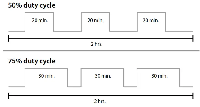
If you have a set point of 20°C, the thermostat will use its full power until the temperature is 19°C. The thermostat will then begin to regulate the output from 19°C with a 75% duty cycle until it reaches 19,25°C. When the temperature has reached 19.5°C the thermostat will use a 50% duty cycle, until it reaches 20°C, then the thermostat turns off and repeats the process. For example, at a 75% duty cycle, it will turn ON for a total of 90 minutes and OFF for 30 minutes.
PROGRAMMING THE THERMOSTAT
To activate the programming mode, press Center (confirm) for 10 seconds. The display will show OFF. You are now in programming mode. To scroll up and down in the menu, use buttons 1 and 3 (left and right) to navigate. To enter the submenu, press Center (confirm).
Always confirm your setting by pressing Center (confirm) for 2 seconds. Sto will appear to indicate saved settings.
TEMPERATURE SHOWN IN DISPLAY
By default, the temperature shown on the display is the setpoint. This may be altered with parameter 13: “Temperature display”. You may calibrate the sensor values ±4 degrees using parameters 10 to 12.
STANDBY AND MAIN SCREEN
When the thermostat remains untouched for a while, it will automatically revert to the standby screen. The standby screen will by default show the setpoint temperature. By pressing any button once, you will see the measured temperature. By pressing the left or right (up or down) button one more time, you will change the setpoint.
Menu structure
OFF Turns the thermostat off.
Sensors:
CHOICE OF SENSORS
| F SEn CAE CAF CAr br1 Con dIF Leo AHI Flo FRI A2L A2H ESC | Depending on your choice of sensors, the menu will change. Select the right Ohm value for your external/floor sensor. NTC type (10, 12, 15, 22, 33 or 47kΩ). Default 10kΩ. Calibration for the external sensor. Calibration for floor sensor. Calibration for the internal sensor. The display brightness may be adjusted in this menu. Activation of inclusion/exclusion mode. Hysteresis. Setting the lowest allowed temperature (limitation). (Air sensor) Setting the highest allowed temperature (limitation). (Air sensor) Setting the lowest allowed temperature (limitation). (Floor sensor) Setting the highest allowed temperature (limitation). (Floor sensor) Setting the lowest allowed temperature (limitation). (A2 air sensor) Setting the highest allowed temperature (limitation). (A2 air sensor) Escape – exit programming menu. |
CHOICE OF SENSOR
The thermostat has a range of choices when it comes to sensors.
To access the menu, press Center (confirm) for 10 seconds, then pressRight (down) once. An A will appear on the display. Then press Center(confirm) again and choose modes while moving up and down with buttons Left or Right:
| F A AF A2 A2F | Floor sensor Internal sensor internal sensor + Floor sensor External room sensor External room sensor + Floor sensor |
When you have chosen sensor mode, press the Center (confirm) button.
If you choose F without having a floor sensor connected, Er4 will be shown in the display. If you choose A2 or A2F and there is no external sensor installed, Er5 will be displayed on the screen.
NOTE: Wooden floors require that a floor sensor is connected in order to limit the floor temperature to a maximum of 27°C (in accordance with specifications from most wooden floor manufacturers).
When using the thermostat is used in (AF or A2F) the floor limiter FHI is automatically set to 27°C. When using any other sensor type (A, F, or A2F) the max temperature is default 5°C minimum and 40°C maximum.
SELECTING THE RIGHT OHM VALUE FOR YOUR EXTERNAL FLOOR SENSOR
The following values are available: NTC type (10, 12, 15, 22, 33, or 47kΩ).
Default 10kΩ. Confirm with the Center (confirm) button.
You can not combine two types of NTC sensors.
CALIBRATION
(CAr, CAF, CAE – Parameters 10, 11, 12)
Using Floor / External sensor (F, A2 or A2F-mode)
In this mode, you may adjust the displayed temperature. If the temperature sensor is not calibrated properly, you can make minor changes to the temperature readout. You can calibrate the measured temperature by up to ±4°C.
You may later adjust the temperature recorded by the sensor using the menu structure or using parameters.
| SENSOR TYPE | CALIBRATION FROM MENU STRUCTURE | PARAMETER |
| Internal Sensor | CAr | 10 |
| Floor Sensor | CAF | 11 |
| External Sensor | CAE | 12 |
BRIGHTNESS
Use the Left and Right (up and down) buttons to adjust the brightness level from 0 to 9. Confirm with the Center (confirm) button.
HYSTERESIS (dIF)
In this mode, you can make changes to the thermostat hysteresis. You may change the hysteresis from 0,3°C up to a max of 3,0°C. Confirm with the Center (confirm) button. The Default setting is 0,5°C. When using water-based heating, the recommended hysteresis is a minimum of 1,0°C.
This only applies when using a floor sensor or an external sensor.
MIN/MAX TEMPERATURE SETTINGS
| Flo FRI Leo AHI ESC | Min Floor temperature Max Floor temperature Min Air/room temperature Max Air/room temperature Confirm with Center (confirm) Leaving programming mode. Confirm with the Center (confirm) button. |
When using the thermostat is used in (AF or A2F) the floor limiter FHI is automatically set to 27°C. When using any other sensor type (A, F, or A2F) the max temperature is default 5°C minimum and 40°C maximum.
FAST FUNCTIONS FROM STANDBY / MAIN SCREEN
This is a list of some functions that you may use without entering the menu structure. From standby modus you may do the following:
DISPLAY ON/OFF (don/doF)
Activate by pressing the Left and Center (up and confirm) buttons for 10 seconds. The display light is temporarily activated if one of the buttons is pushed.
In case doF is activated, the screen will be blank (may be used if installed where people are sensitive to the display light). When touching the display, the screen lights up.
CHILD LOCK (LOC)
By pressing the Left and Right (up and down) buttons for 10 seconds, the child lock will be activated, and no changes can be made. Trying to make changes causes the LOC text to appear on the display.
Child lock is deactivated by pressing the Left and Right (up and down) buttons for 10 seconds. OPn will appear on the display.
ERROR CODES
| Err Er1 Er2 Er3 Er4 Er5 | Adding fail See Chapter 6.1 ”Add/Remove”. Internal error Contact your local dealer. Z-Wave error Contact your local dealer. Internal error Contact your local dealer. Floor sensor error You have chosen F, AF, or A2F sensor mode without having a floor sensor connected, or the sensor may be damaged. External sensor error You have chosen A2 or A2F, and there are no external sensors installed or the sensor may be damaged. |
-WAVE QR-CODE / DSC
The QR-Code is needed when including a device using S2 security or SmartStart. The Z-Wave DSK can be found in the QR-Code which is located in 3 locations:
- On the product box.
- On the physical product, placed on the black plastic underneath the front.
- On the PCB internally.
SECURITY
S2 security enhances Z-Wave Plus with an additional layer of AES 128-bit encryption of the wireless Z-Wave communication to prevent hacking and man-in-middle attacks on the home network. This device supports S2 and has a Z-Wave DSK QR-Code label that may be used when the module is added to the Z-Wave home network. The primary controller will ask for a 5-digit code, which can be found underneath the QR-Code. The primary controller will then ask you to confirm the rest of the code that is contained in the QR-Code.
NODE INFORMATION FRAME
The node information frame is the ”business card” of a Z-Wave device.
It contains information about the device type and its technical features.
The add and remove procedure of the device is confirmed by sending out a node information frame. Besides this, it may be necessary for certain network operations to send out a node information frame.
ASSOCIATIONS
Z-Wave devices interact with other Z-Wave devices. The relationship between one device controlling another device is called an association. In order to control a subordinate device, the controlling device needs to maintain a list of devices that will receive controlling commands. These lists are called ”Association Groups”. They are always related to the specific event triggered (e.g., sensor reports). In case the event is triggered, all devices stored in the respective association group will receive a joint wireless command.
SETTING AND REMOVING ASSOCIATIONS
Associations may be assigned and removed via Z-Wave commands.
Please refer to your primary controller/Z-Wave gateway for more information.
MULTICHANNEL SUPPORT
Heatit Z-TRM3 has support for the Multichannel Command Class. This allows the thermostat to be perceived as many devices by the primary controller, where each of the devices has association groups in order to send information to other Z-Wave devices. See the chapter concerning ”Association Groups” for more information. Commands sent to each logical device will be interpreted according to the description in the section ”Supporting Command Classes”.
NO MULTICHANNEL SUPPORT
If the primary controller or the Z-Wave devices to be associated with Heatit Z-TRM3 do not support the Multichannel Command Class (Multichannel encapsulation), only the association groups in the root device are accessible. This device contains 5 association groups.
See Chapter 23 concerning ”Association Groups” for more information.
The root device is the actual thermostat device.
ASSOCIATION GROUPS WITH MULTICHANNEL SUPPORT
When used in a system with Multichannel support:
| THERMOSTAT DEVICE 1 | THE MAIN THERMOSTAT DEVICE |
| Group 1 Group 2 | Lifeline. (Normally used by the Z-Wave Controller) Sends: -Thermostat Setpoint Reports -Thermostat Mode Reports -Thermostat Operating State -Meter Reports Max. nodes in the group: 5 Send Binary Switch Set commands representing the status of the internal relay. Max. nodes in the group: 5 |
| MULTILEVEL SENSOR DEVICE 2 | DEVICE FOR INTERNAL ROOM TEMPERATURE SENSOR |
| Group 1 Group 2 | Lifeline Send Multilevel Sensor Reports. Max. nodes in the group: 5 Send Multilevel Sensor Reports. Max. nodes in the group: 5 |
| MULTILEVEL SENSOR DEVICE 3 | DEVICE FOR EXTERNAL ROOM TEMPERATURE SENSOR |
| Group 1 Group 2 | Lifeline Send Multilevel Sensor Reports. Max. nodes in the group: 5 Send Multilevel Sensor Reports. Max. nodes in the group: 5 |
| MULTILEVEL SENSOR DEVICE 4 | DEVICE FOR FLOOR SENSOR |
| Group 1 Group 2 | Lifeline Send Multilevel Sensor Reports. Max. nodes in the group: 5 Send Multilevel Sensor Reports. Max. nodes in the group: 5 |
ASSOCIATION GROUPS WITHOUT MULTICHANNEL SUPPORT
When used in a system without Multi-Channel support:
| Group 1 Lifeline | Lifeline. (Normally used by the Z-Wave Controller) Sends: – Device Reset Notifications. – Thermostat Setpoint Reports – Thermostat Mode Reports – Thermostat Operating State – Basic Reports – Meter Reports Max. nodes in the group: 5 |
| Group 2 State of relay ON/OFF | Send Binary Switch Set commands representing the status of the internal relay. Max. nodes in the group: 5 |
| Group 3 Internal sensor | Send Multilevel Sensor Reports for the internal temperature sensor. Max. nodes in the group: 5 |
| Group 4 External sensor | Send Multilevel Sensor Reports for the external room temperature sensor. Max. nodes in the group: 5 |
| Group 5 Floor sensor | Send Multilevel Sensor Reports for floor sensor. Max. nodes in the group: 5 |
CONFIGURATION PARAMETERS
Z-Wave products are supposed to work out of the box after inclusion.
Some device configurations may, however, alter the functionality to better serve user needs or unlock further enhanced features.
Parameter 1, Parameter Size 1. Operation mode
| VALUE | DESCRIPTION |
| 0 | Off |
| 1 | Heating mode (Default) |
Parameter 2, Parameter Size 1. Sensor mode
| VALUE | DESCRIPTION |
| 0 | F-mode, floor sensor mode |
| 1 | A-mode, internal room sensor mode (Default) |
| 2 | AF-mode, internal room sensor with floor limitation |
| 3 | A2-mode, external room sensor mode |
| 4 | A2F-mode, an external sensor with floor limitation |
Parameter 3, Parameter Size 1. Floor sensor type
| VALUE | DESCRIPTION |
| 0 | 10K NTC (Default) |
| 1 | 12K NTC |
| 2 | 15K NTC |
| 3 | 22K NTC |
| 4 | 33K NTC |
| 5 | 47K NTC |
Parameter 4, Parameter Size 1. Temperature control hysteresis (diF)
| VALUE | DESCRIPTION |
| 3 to 30 | 0.3°C to 3.0°C. Default is 5 (0.5°C) |
Parameter 5, Parameter Size 2. Floor minimum temperature limit (Flo)
| VALUE | DESCRIPTION |
| 50 to 400 | 5.0°C to 40.0°C. Default is 50 (5.0°C) |
Parameter 6, Parameter Size 2. Floor maximum temperature limit (FHI)
| VALUE | DESCRIPTION |
| 50 to 400 | 5.0°C to 40.0°C. Default is 400 (40.0°C) |
Parameter 7, Parameter Size 2. Air (A2) minimum temperature limit (ALo)
| VALUE | DESCRIPTION |
| 50 to 400 | 5.0°C to 40.0°C. Default is 400 (40.0°C) |
Parameter 8, Parameter Size 2. Air (A2) maximum temperature limit (AHi)
| VALUE | DESCRIPTION |
| 50 to 400 | 5.0°C to 40.0°C. Default is 400 (40.0°C) |
Parameter 9, Parameter Size 2. Heating mode setpoint
| VALUE | DESCRIPTION |
| 50 to 400 | 5.0°C to 40.0°C. Default is 210 (21.0°C) |
Parameter 10, Parameter Size 1. Room sensor calibration (A)
NB. To set a negative value, use 256 and subtract the desired value.
| VALUE | DESCRIPTION |
| -60 to 60 | -6.0°C to 6.0°C. Default is 0 (0.0°C) |
Parameter 11, Parameter Size 1. Floor sensor calibration
NB. To set a negative value, use 256 and subtract the desired value.
| VALUE | DESCRIPTION |
| -60 to 60 | -6.0°C to 6.0°C. Default is 0 (0.0°C) |
Parameter 12, Parameter Size 1. External sensor calibration
NB. To set a negative value, use 256 and subtract the desired value.
| VALUE | DESCRIPTION |
| -60 to 60 | -6.0°C to 6.0°C. Default is 0 (0.0°C) |
Parameter 13, Parameter Size 1. Temperature display
Selects which temperature is shown on the display.
Refer to Chapter 11 ”Standby and main screen”.
| VALUE | DESCRIPTION |
| 0 | Display setpoint temperature (Default) |
| 1 | Display measured temperature |
Parameter 14, Parameter Size 1. Button brightness – dimmed state
Configure the brightness of the buttons in the dimmed state.
| VALUE | DESCRIPTION |
| 0 to 100 | 0 to 100% (Default 50%) |
Parameter 15, Parameter Size 1. Button brightness – active state
Configure the brightness of the buttons in the active state
| VALUE | DESCRIPTION |
| 0 to 100 | 0 to 100% (Default 100%) |
Parameter 16, Parameter Size 1. Display brightness – dimmed state
Configure the brightness of the display in the dimmed state.
| VALUE | DESCRIPTION |
| 0 to 100 | 0 to 100% (Default 50%) |
Parameter 17, Parameter Size 1. Display brightness – active state
Configure the brightness of the display, in an active state.
| VALUE | DESCRIPTION |
| 0 to 100 | 0 to 100% (Default 100%) |
Parameter 18, Parameter Size 2. Temperature report interval
The time interval between consecutive temperature reports.
Temperature reports can also be sent as a result of polling.
| VALUE | DESCRIPTION |
| 30 to 32767 | 30 seconds to 32767 seconds. Default is 60 seconds |
Parameter 19, Parameter Size 1. Temperature report hysteresis
The temperature report will be sent if there is a difference in temperature value
from the previous value reported, defined in this parameter (hysteresis).
Temperature reports can also be sent as a result of polling.
| VALUE | DESCRIPTION |
| 1 to 100 | 0.1°C to 10.0°C. Default is 10 (1.0°C) |
Parameter 20, Parameter Size 2. Meter report interval
The time interval between consecutive meter reports.
Meter reports can also be sent as a result of polling.
| VALUE | DESCRIPTION |
| 30 to 32767 | 30 seconds to 32767 seconds. Default is 90 seconds |
Parameter 21, Parameter Size 1. Meter report delta value
Delta value in kWh between consecutive meter reports.
Meter reports can also be sent as a result of polling.
| VALUE | DESCRIPTION |
| 0 | Reporting meter based on change is disabled |
| 0 to 255 | A delta value of 0 to 25.5 kWh will result in a metering report. Default is 10 (1.0 kWh) |
COMMAND CLASS SPECIFICATIONS SUPPORTED COMMAND CLASSES
The following table lists all Command Classes supported by the Z-Wave device. The device supports both S0, and S2 Authenticated security, and S2 Unauthenticated security.
| INSECUREINCLUSION | INSECURE ON SECURE INCLUSION | SECURE ON SECURE INCLUSION | |
| Z-Wave Plus Information v2 | Yes | Yes | |
| Association v2 | Yes | Yes | |
| Association Group Information v1 | Yes | Yes | |
| Multilevel Sensor v5 | Yes | Yes | |
| Multichannel Association v3 | Yes | Yes | |
| Multichannel v4 | Yes | Yes | |
| Transport Service v2 | Yes | Yes | |
| Version v3 | Yes | Yes | |
| Manufacturer Specific v2 | Yes | Yes | |
| Device Reset Locally v1 | Yes | Yes | |
| Powerlevel v1 | Yes | Yes | |
| Security v1 | Yes | Yes | |
| Security 2 v1 | Yes | Yes | |
| Supervision v1 | Yes | Yes | |
| Configuration v3 | Yes | Yes | |
| Firmware Update v5 | Yes | Yes | |
| Thermostat Setpoint v3 | Yes | Yes | |
| Thermostat Mode v3 | Yes | Yes | |
| Thermostat Operating State v1 | Yes | Yes | |
| Basic v2 | Yes | Yes | |
| Meter v3 | Yes | Yes |
SUPPORTED COMMAND CLASSES
Besides the mandatory command classes, Heatit Z-TRM3 has support for the following command classes:
Basic Command Class
A Basic command to the root endpoint or endpoint 1 will change the Thermostat Mode. Uses the following values:
0x00 = OFF (thermostat regulation is deactivated)
0x01 = Heating Mode (thermostat regulation is active)
Binary Switch Command Class
Sends Binary Switch commands to other devices when the internal relay is switched. It was used to control other slave relay devices. Uses the following values:
0x00 = OFF
0xFF = ON
Thermostat Setpoint Command Class
When a Thermostat Setpoint Set command is received by the root device, it sets the chosen setpoint for heating mode.
Thermostat Mode
It is possible to change the operating mode of the thermostat by sending a Thermostat Mode Set command. The accessible operating modes are:
0x00 = OFF (thermostat regulation is deactivated)
0x01= Heating Mode (thermostat regulation is active)
Thermostat Operating State
The thermostat reports the operating state of the internal relay using this command class.
0x00 = Idle (relay is turned OFF)
0x01= Heating (relay is turned ON)
Meter Command Class
The thermostat supports Meter Command Class Get, and the thermostat will only respond on supported electric meter scales: kWh (accumulated), Watt (instant) and Volt (instant). The thermostat will report when asked:
Rate import: Import (0x01)
Meter type: Electric meter (0x01)
Precision: 1 decimal (0x01)
| PRECISION (VALUE) | SCALE SUPPORTED (VALUE) | SIZE |
| 1 decimal (0x01) | kWh (0x01) | 4 |
| 2 decimals (0x01) | W (0x02) | 4 |
| 1 decimal | V (0x04) | 2 |
THERMOSTAT DEVICE 1
Supported Command Classes Association (version 2)
Z-Wave Plus Information (version 2)
Association (version 2)
Association Group Information (version 3)
Multichannel Association (version 3)
Supervision (version 1)
Security (version 1)
Security 2 (version 1)
Thermostat Setpoint (version 3)
Thermostat Mode (version 3)
Thermostat Operating State (version 1)
Controlled Command Classes
Switch Binary (version 1)
Meter (version 3)
MULTILEVEL SENSOR DEVICE 2
Supported Command Classes
Z-Wave Plus Information (version 2)
Association (version 2)
Association Group Information (version 3)
Multichannel Association (version 3)
Supervision (version 1)
Security (version 1)
Security 2 (version 1)
Multilevel Sensor (version 5)
Controlled Command Classes
Multilevel Sensor (version 5)
MULTILEVEL SENSOR DEVICE 3
Supported Command Classes
Z-Wave Plus Information (version 2)
Association (version 2)
Association Group Information (version 3)
Multichannel Association (version 3)
Supervision (version 1)
Security (version 1)
Security 2 (version 1)
Multilevel Sensor (version 5)
Controlled Command Classes
Multilevel Sensor (version 5)
MULTILEVEL SENSOR DEVICE 4
Supported Command Classes
Z-Wave Plus Information (version 2)
Association (version 2)
Association Group Information (version 3)
Multichannel Association (version 3)
Supervision (version 1)
Security (version 1)
Security 2 (version 1)
Multilevel Sensor (version 5)
Controlled Command Classes
Multilevel Sensor (version 5)
SMARTSTART![]() PRODUCT INFO HEATIT Z-TRM3
PRODUCT INFO HEATIT Z-TRM3
FUNCTIONS
| • Floor sensor • Internal room sensor • External room sensor (connected by cable) • Temperature limiter • SmartStart • Weekly program/ setback via the gateway • Supports encryption mode: S0, S2 Authenticated Class, S2 Unauthenticated Class | • Temperature read out in the gateway • Firmware update (OTA) • Power metering • Relay status LED • Single pole switch • Lock mode/child lock • Calibration • 5 associations |
This product is a security-enabled Z-Wave Plus product with encryption. The product must be used with a security-enabled Z-Wave Controller in order to fully utilize the product.
TECHNICAL DATA
| Protocol Chip Rated voltage Max load Max current Power consumption Ambient temperature Temperature range Hysteresis Compatible with NTC sensors with values IP Code Approvals | Z-Wave – 868,4MHz Z-Wave 500 chip 230V 50/60Hz 3600W (resistive load) 750W self-limiting heating cable 16A <2,0W 0°C to 40°C (during operation) 5°C to 40°C 0,3°C to 3,0°C (default 0,5°C) 10, 12, 15, 22, 33 and 47 kΩ @ 25°C IP 21 Z-Wave Plus, CE, EN 60730-1, EN 60730-2-9, EMC 2014/30EU, RoHS 2011/65/EU, LVD 2014/35/EU |
Approved for use in bathrooms.
TERMINAL
Use 1,5mm² or 2,5mm² according to load.
MAINTENANCE
The product is maintenance-free, but must not be covered.
| ART. NO. | PRODUCT | COLOR | Z-WAVE FREQUENCY |
| 54 305 99 | Heatit Z-TRM3 thermostat 3600W 16A | White RAL 9003 | EU 868,4MHz |
| 54 305 98 | Heatit Z-TRM3 thermostat 3600W 16A | Black RAL 9011 | EU 868,4MHz |
| 54 304 46 | Plastic kit for Heatit (front and frame) | Black RAL 9011 | |
| 99 305 60 | Heatit Z-TRM3 thermostat 3600W 16A | White RAL 9003 | RU 869,0MHz |
| 99 305 51 | Heatit Z-TRM3 thermostat 3600W 16A | White RAL 9003 | AUS 921,4MHz |
Heatit Controls AB can not be held liable for typographical errors, other errors, or omittances in our information.
Product specifications may change without further notice.
All electrical installations must be carried out by a licensed electrician.
The product must be installed in accordance with national building codes and our installers manual.
![]() Heatit Controls AB
Heatit Controls AB
Phone: +47 61 18 77 77 l
[email protected]
www.heatit.com


 Heatit Z-trm3 Heae5430599 Manual")

 Heatit Z-trm2fx Heae5430555 Manual")


 Heatit Z-wave Thermostat Heae5430499 Manual")


 Z-temp2 Heae4512666 Manual")


