HEATIT Z-TRM2fx Thermostat for Electrical Floor Heating Installation Guide

IMPORTANT
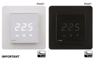
PLEASE READ THIS BEFORE INSTALLATION
This Heatit device is certified by Pepper One Gmbh according to the requirements set forward by the Z-Wave Alliance and
Silicon Labs. This is a Z-Wave Plus product with the 500 series chip. If the product does not work with your gateway, then the gateway manufacturer has not made an integration for such a device. We do not give any guarantee towards integration.
PRINCIPLES FOR REGULATION
Heatit Z-TRM2fx is designed for controlling electrical heating cables and electrical radiators/convectors. The thermostat uses an external temperature sensor. After you have set the temperature, the thermostat will use a hysteresis to regulate the temperature. The hysteresis is adjustable.
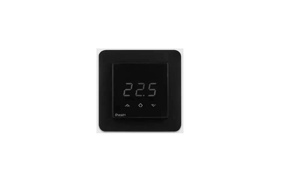
TEMPERATURE SHOWN IN DISPLAY
The temperature shown in the display is the actual temperature for floor sensor and the external room sensor. You are able to calibrate the sensor values.
Z-WAVE THERMOSTAT – SETUP
This manual describes the most essential functions and technical specifications of the thermostat. These instructions help the user to control the thermostat, and the electrician to install and setup the thermostat.
FACTORY RESET
By pressing buttons Right and Center (down and confirm) for 20 seconds, the thermostat will perform a complete factory reset. NB! Please use this procedure only when the primary controller/
gateway is missing or otherwise inoperable
BEHAVIOR WITHIN THE Z-WAVE NETWORK
This product can be operated in any Z-Wave network with other Z-Wave certified devices from other manufacturers. All nonbattery operated nodes within the network will act as repeaters
regardless of vendor to increase reliability of the network.
On delivery, the device does not belong to any Z-Wave network. The device needs to be added to an existing wireless network to communicate with the devices of this network. Devices can also be removed from a network. Both add and remove process are initiated by the primary controller of the Z-Wave network.
This controller will be turned into a mode for adding or removing devices. Please refer to your primary controllers manual on how to turn your controller into add or remove mode. Only if the primary controller is in add or remove mode, this device can be added or removed from the network. When the device is removed from the network, it will set the device back to factory default.
If the device already belongs to a network, follow the remove process before adding it in your network. Otherwise, the adding of this device will fail.
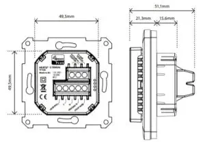
INSTALLATION
Installation must be done by a qualified electrical installer in accordance with the National Building codes. Before installation, disconnect any power to the thermostat’s mains. During installation of the thermostat, power to the thermostat must be disconnected AT ALL TIMES!
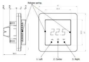
Use e.g. a small slotted screwdriver. Start by carefully removing the front cover by pushing the release springs. The front cover and the frame can now be removed.
Now connect the wires to the thermostat’s terminals: Use 1,5mm² or 2,5mm² according to load.
HEATING (N) Heating cable connection (Neutral)
N Power connection (Neutral) 230V
L Power connection (Live) 230V
HEATING (L) Heating cable connection (Live)
PILOT 230V pilot signal (ECO temp)
FLOOR SENSOR NTC type (10, 12, 15, 22, 33 or 47kΩ). Default 10kΩ.
EXTERNAL SENSOR NTC type (10, 12, 15, 22, 33 or 47kΩ). Default 10kΩ.
Next, position the thermostat and fasten it onto the wall’s mounting box using 2-4 screws. Position the frame, then position and carefully press the front cover until it snaps in place. Check that the front cover has snapped in place properly on both left and right side. The front cover should now be firmly fixed on all sides.
To be able to to read the Power Metering, the load needs to be connected to both heating L + N.
NOTE! Top cover has to be installed when the thermostat is connected to mains. The thermostat is not SELV product. All voltage parts are considered as 230VAC.
STARTUP
AFTER CONNECTING THE POWER TO THE THERMOSTAT FOR THE FIRST TIME, ALL PARAMETERS WILL HAVE DEFAULT SETTINGS.
CONTROL
The thermostat is controlled by three touch sensitive capacitive buttons.
You only need to touch lightly to activate the buttons. 1: Left (Up)
2: Center (Confirm)
3: Right (Down)
ADDING/REMOVING
To add or remove the thermostat to your home automation gateway, press Center (confirm) for 10 seconds.
The display will show OFF. Press Right (down) 4 times till you see Con in the display. Now start add/remove device in your home automation software. Start adding/removing mode by pressing Center (confirm) for approximately 2 seconds. Adding/removing Mode is indicated in the display by some “circling” LED segments in the display until the timeout occurs after 20 seconds or the module has been added/removed in the network. Confirmation will show Inc/EcL in the display. If adding/removing fails, Err (error) will appear. Leave programming mode by choosing ESC in menu. Your thermostat is ready for use with default settings.
PROGRAMMING YOUR THERMOSTAT
To activate the programming mode, press Center (confirm) for 10 seconds. Now the display will show OFF.
Now you are in programming mode. To scroll up and down in the menu use button 1 and 3 (left and right) to navigate. To enter submenu press Center (confirm). Always confirm your setting by pressing Center (confirm) for 2 seconds.
OFF Turns the thermostat off. Sensors:
- F Choice of sensors
Depending on your choice of sensors, the menu will change.
NODE INFORMATION FRAME
The Node Information Frame is the business card of a Z-Wave device. It contains information about the device type and the technical capabilities. The inclusion and exclusion of the device is confirmed by sending out a Node Information Frame. Beside this, it may be necessary for certain network operations to send out a Node Information Frame
ASSOCIATIONS
Z-Wave devices control other Z-Wave devices. The relationship between one device controlling another device is called association. In order to control a different device, the controlling device needs to maintain a list of devices that will receive controlling commands. These lists are called association groups and they are always related to certain events (e.g. sensor reports, …). In case the event happens all devices stored in the respective association group will receive a common wireless command.
Association Groups (Multi Channel support)
When using Heatit Z-TRM2fx in a Multi Channel environment:
| THERMOSTAT DEVICE 1 | THE MAIN THERMOSTAT DEVICE |
| Group 1 | Lifeline. (Normally used by the Z-Wave Controller) Sends: – Thermostat Setpoint Reports – Thermostat Mode Reports Max. nodes in group: 0 |
| MULTILEVEL SENSOR DEVICE 2 | DEVICE FOR EXTERNAL ROOM TEMPERATURE SENSOR |
| Group 1 | Lifeline Max. nodes in group: 0 |
| Send Multilevel Sensor Reports. | |
| Group 2 | Max. nodes in group: 5 |
| MULTILEVEL SENSOR DEVICE 3 | DEVICE FOR FLOOR SENSOR |
| Group 1 | Lifeline Max. nodes in group: 0 |
| Send Multilevel Sensor Reports. | |
| Group 2 | Max. nodes in group: 5 |
| BINARY SWITCH DEVICE 4 | DEVICE FOR THE INTERNAL RELAY |
| Group 1 | Lifeline Max. nodes in group: 0 |
| Send Binary Switch Set commands representing | |
| Group 2 | the status of the internal relay. Max. nodes in group: 5 |
Association Groups (when no Multi Channel support)
When used in a system with no Multi Channel support:
| THERMOSTAT DEVICE | THE MAIN THERMOSTAT DEVICE |
| Group 1 | Lifeline. (Normally used by the Z-Wave Controller) Sends: – Device Reset Notifications. – Thermostat Setpoint Reports – Thermostat Mode Reports – Basic Reports – Meter Reports Max. nodes in group: 5 |
| Group 2 | Send Multilevel Sensor Reports for external temperature sensor. Max. nodes in group: 5 |
| Group 3 | Send Multilevel Sensor Reports for floor temperature sensor. Max. nodes in group: 5 |
| Group 4 | Send Binary Switch Set commands representing the status of the internal relay. Max. nodes in group: 5 |
Setting and Removing Associations
Associations can be assigned and removed via Z-Wave commands.
CONFIGURATION PARAMETERS
Z-Wave products are supposed to work out of the box after inclusion, however certain configuration of a device can alter the functionality to better serve the user’s needs or unlock further enhanced.
features.
Parameter 1, Parameter Size 1. Operation mode
| VALUE | DESCRIPTION |
| 0 | Off. (Default) |
| 1 | Heating mode |
| 2 | Cooling mode |
| 11 | Energy saving heating mode |
Parameter 2, Parameter Size 1. Sensor mode
| VALUE | DESCRIPTION |
| 0 | F-mode, floor sensor mode. (Default) |
| 3 | A2-mode, external room sensor mode |
| 4 | A2F-mode, external sensor with floor limitation |
Parameter 3, Parameter Size 1. Floor sensor type
| VALUE | DESCRIPTION |
| 0 | 10K NTC. (Default) |
| 1 | 12K NTC |
| 2 | 15K NTC |
| 3 | 22K NTC |
| 4 | 33K NTC |
| 5 | 47K NTC |
Parameter 4, Parameter Size 1. Temperature control hysteresis (DIFF I)
| VALUE | DESCRIPTION |
| 3 – 30 | 0.3°C – 3.0°C. Default is 5 (0.5°C) |
Parameter 5, Parameter Size 2. Floor minimum temperature limit (FLo)
| VALUE | DESCRIPTION |
| 50 – 400 | 5.0°C – 40.0°C. Default is 50 (5.0°C) |
Parameter 6, Parameter Size 2. Floor maximum temperature limit (FHi)
| VALUE | DESCRIPTION |
| 50 – 400 | 5.0°C – 40.0°C. Default is 400 (40.0°C) |
Parameter 7, Parameter Size 2. Air (A2) minimum temperature limit (ALo)
| VALUE | DESCRIPTION |
| 50 – 400 | 5.0°C – 40.0°C. Default is 50 (5.0°C) |
Parameter 8, Parameter Size 2. Air (A2) maximum temperature limit (AHi)
| VALUE | DESCRIPTION |
| 50 – 400 | 5.0°C – 40.0°C. Default is 400 (40.0°C) |
Parameter 9, Parameter Size 2. Heating mode setpoint (CO)
| VALUE | DESCRIPTION |
| 50 – 400 | 5.0°C – 40.0°C. Default is 210 (21.0°C) |
Parameter 10, Parameter Size 2. Energy saving mode setpoint (ECO)
| VALUE | DESCRIPTION |
| 50 – 400 | 5.0°C – 40.0°C. Default is 180 (18.0°C) |
Parameter 11, Parameter Size 2. Cooling setpoint (COOL)
| VALUE | DESCRIPTION |
| 50 – 400 | 5.0°C – 40.0°C. Default is 210 (21.0°C) |
Parameter 12, Parameter Size 1. Floor sensor calibration
- NB. To set a negative value, use 255 and subtract the desired value.
| VALUE | DESCRIPTION |
| -40 – 40 | -4.0°C – 4.0°C. Default is 0 (0.0°C) |
Parameter 13, Parameter Size 1. External sensor calibration
NB. To set a negative value, use 255 and subtract the desired value.
| VALUE | DESCRIPTION |
| -40 – 40 | -4.0°C – 4.0°C. Default is 0 (0.0°C) |
Parameter 14, Parameter Size 1. Temperature display Selects which temperature is shown in the display
| VALUE | DESCRIPTION |
| 0 | Display measured temperature (Default) |
| 1 | Display setpoint temperature |
Parameter 15, Parameter Size 1. Button brightness – dimmed state Configure the brightness of the buttons, in dimmed state
| VALUE | DESCRIPTION |
| 0 – 100 | 0 – 100% (Default 50%) |
Parameter 16, Parameter Size 1. Button brightness – active state Configure the brightness of the buttons, in active state
| VALUE | DESCRIPTION |
| 0 – 100 | 0 – 100% (Default 100%) |
Parameter 17, Parameter Size 1. Display brightness – dimmed state Configure the brightness of the display, in dimmed state.
| VALUE | DESCRIPTION |
| 0 – 100 | 0 – 100% (Default 50%) |
Parameter 18, Parameter Size 1. Display brightness – active state Configure the brightness of the display, in active state.
| VALUE | DESCRIPTION |
| 0 – 100 | 0 – 100% (Default 100%) |
Parameter 19, Parameter Size 2. Temperature report interval
Time interval between consecutive temperature reports. Temperature reports can be also sent as a result of polling
| VALUE | DESCRIPTION |
| 0 | Reporting of temperatures disabled |
| 30 – 32767 | 30 seconds – 32767 seconds. Default is 60 seconds |
Parameter 20, Parameter Size 1. Temperature report hysteresis
The temperature report will be sent if there is a difference in temperature value from the previous value reported, defined in this parameter (hysteresis). Temperature reports can be also sent as a result of polling.
| VALUE | DESCRIPTION |
| 1 – 100 | 0.1°C – 10.0°C. Default is 10 (1.0°C) |
Parameter 21, Parameter Size 2. Meter report interval
Time interval between consecutive meter reports. Meter reports can be also sent as a result of pollin
| VALUE | DESCRIPTION |
| 0 | Reporting of metering values is disabled |
| 30 – 32767 | 30 seconds – 32767 seconds. Default is 60 seconds |
Parameter 22, Parameter Size 1. Meter report delta value
Delta value in kWh between consecutive meter reports. Meter reports can be also sent as a result of polling.
| VALUE | DESCRIPTION |
| 0 – 127 | A delta value of 0 – 12.7 kWh will result in a metering report. Default is 10 (1.0 kWh) |
COMMAND CLASSES
Z-Wave products are supposed to work out of the box after inclusion, however certain configuration of a device can alter the functionality
to better serve the user’s needs or unlock further enhanced features
| INSECURE INCLUSION | INSECURE ON SECURE INCLUSION | SECURE ON SECURE INCLUSION | |
| Association (version 2) | Yes | Yes | |
| Association Group Information (version 1) | Yes | Yes | |
| Multi Channel Association (version 3) | Yes | Yes | |
| Version (version 3) | Yes | Yes | |
| Configuration (version 3) | Yes | Yes | |
| Manufacturer Specific (version 2) | Yes | Yes | |
| Z-Wave Plus Information (version 2) | Yes | Yes | |
| Device Reset Locally (version 1) | Yes | Yes | |
| Powerlevel (version 1) | Yes | Yes | |
| Firmware Update (version 4) | Yes | Yes | |
| Multi Channel (version 4) | Yes | Yes | |
| Basic (version 2) | Yes | Yes | |
| Supervision (version 1) | Yes | Yes | |
| Multilevel Sensor (version 5) | Yes | Yes | |
| Thermostat Setpoint (version 3) | Yes | Yes | |
| Thermostat Mode (version 3) | Yes | Yes | |
| Switch Binary (version 1) | Yes | Yes | |
| Meter (version 3) | Yes | Yes | |
| Security (version 1) | Yes | Yes | |
| Security 2 (version 1) | Yes | Yes |
Controlled Command Classes Multilevel Sensor (version 5) Thermostat Setpoint (version 3) Thermostat Mode (version 3) Switch Binary (version 1)
Meter (version 3)
THERMOSTAT DEVICE 1
Supported Command Classes Association (version 2)
Association Group Information (version 1) Multi Channel Association (version 3)
Z-Wave Plus Information (version 2) Supervision (version 1)
Thermostat Setpoint (version 3) Thermostat Mode (version 3) Security (version 1)
Controlled Command Classes
MULTILEVEL SENSOR DEVICE 2
Supported Command Classes Association (version 2)
Association Group Information (version 1) Multi Channel Association (version 3)
Z-Wave Plus Information (version 2) Supervision (version 1)
Multilevel Sensor (version 5) Security (version 1)
Controlled Command Classes Multilevel Sensor (version 5)
MULTILEVEL SENSOR DEVICE 3
Supported Command Classes Association (version 2)
Association Group Information (version 1) Multi Channel Association (version 3)
Z-Wave Plus Information (version 2) Supervision (version 1)
Multilevel Sensor (version 5) Security (version 1)
Controlled Command Classes Multilevel Sensor (version 5)
BINARY SWITCH DEVICE 4
Supported Command Classes Association (version 2)
Association Group Information (version 1) Multi Channel Association (version 3)
Z-Wave Plus Information (version 2) Supervision (version 1)
Switch Binary (version 1) Meter (version 3) Security (version 1)
Controlled Command Classes Switch Binary (version 1) Meter (version 3)
PRODUCT INFO
- Floor sensor
- External room sensor
- Temperature limiter
- Weekly program/setback via gateway or pilot wire
- Multilevel sensor command class
- Firmware updates (OTA)
- Power metering
- LED-diode
- May be used in connection with different NTC-sensors
- Lock mode/child lock
- Calibration
- 5 associations
- Supports encryption mode: S0, S2 Authenticated Class, S2 Unauthenticated Class
This product is a security enabled Z-Wave Plus product with encryption. The product must be used with a security enabled Z-Wave Controller in order to fully utilize the product.
TECHNICAL DATA
Protocol Z-Wave
SDK 6.71.03
Rated voltage 230V 50/60Hz
Max load 2900W (resistive load)
750W self-limiting heating cable
Max current 13A
Power consumption <2,0W Min/max installation temp -20°C – 40°C Min/max operating temp 5°C – 40°C
Temperature intervals Floor sensor 5°C – 40°C
External room sensor 5°C – 40°C
Hysteresis 0,3°C – 3,0°C (default 0,5°C)
Switch Single-pole switch
Included in package Floor sensor, Art. no. 54 301 07
Compatible with NTC
sensors with values 0, 12, 15, 22, 33 and 47 kΩ @ 25°C
IP Code IP 21
Routing Yes
Explorer Frame Support Yes
Device Type Slave with routing capabilities
Generic Device Class Thermostat
Specific Device Class Thermostat General V2
Approvals Z-Wave Plus CE
EN 60730-1, EN 60730-2-9 EMC 2014/30/EU, RoHS 2011/65/EU LVD 2014/35/EU
| ART. NO. | PRODUCT | COLOR | Z-WAVE FREQUENCY |
| 54 305 60 | Heatit Z-TRM2fx thermostat 2900W 13A | White RAL 9003 | EU 868,4MHz |
| 54 304 46 | Plastic kit for Heatit (front and frame) | Black RAL 9010 |


 Heatit Z-trm2fx Heae5430555 Manual")


 Heatit Z-wave Thermostat Heae5430499 Manual")
 Heatit Z-trm3 Heae5430599 Manual")


