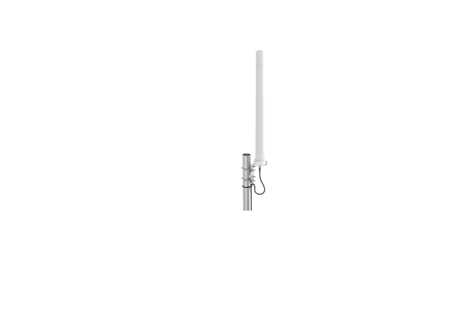
Poynting A-OMNI-0900 High Gain 8dBi Omni Directional Antenna
Product Information
The user manual provides information on the installation of the A-OMNI-0900 Omni-directional antenna, which comes with M8 Stainless Steel nuts, flat washers, hex socket cap screws, securing plate, rubber seal, spanner/wrench, and Allen key. The package includes a 8mm drill bit/hole saw for cables, a centre punch and drilling machine, drilling template, and safety goggles. The antenna can be pole mounted with an optional bracket (BRKT-090), wall-mounted with an optional bracket (BRKT-090), or surface mounted with a supplied fastening plate. The user manual provides exploded views for each mounting option. The user manual also warns to ensure that all RF connections made outdoors are adequately waterproofed and recommends using waterproof connector boots. The user manual includes usage instructions for two cases: Router with two LTE ports (2×2 MIMO) and Router with four LTE ports (4×4 MIMO). The user manual also provides safety precautions for installation, including avoiding installation on a wet or windy day or during lightning or thunder, wearing protective clothing and rubber gloves, avoiding installation while under the influence of drugs, alcohol or medication, securing loose-fitting jewelry or clothing, using safety goggles when drilling holes, avoiding dull or damaged bits, being aware of finger placement in relation to the drill bit when using the drilling machine, and letting the drill chuck come to a complete stop on its own to stop the drilling machine.
Product Usage Instructions
- Choose the appropriate mounting option for your antenna.
- Use the provided tools and equipment to install the antenna according to the exploded view in the user manual.
- Place the rubber seal at the bottom of the antenna and then connect the cable(s) to the antenna before attaching it to the bracket.
- Ensure that all RF connections made outdoors are adequately waterproofed and use waterproof connector boots.
- For Router with two LTE ports (2×2 MIMO), connect the antenna cable labelled Cell 1 (Main) to the respective Cell 1 (Main) connector of your router. Similarly, connect the antenna cable labelled Cell 2 (Main) to the respective Cell 2 (Main) connector of your router. Next, connect the antenna cable labelled Cell 1 (Aux/Div) to the respective Cell 1 (Aux/Div) of your router. Similarly, connect the antenna cable labelled Cell 2 (Aux/Div) to the respective Cell 2 (Aux/Div) port of your router.
- For Router with four LTE ports (4×4 MIMO), follow the same instructions as in step 5 for all four LTE ports on your router.
Packing Check List
| Item | Description | Quantity |
| 1. | A-OMNI-0900 Antenna Only | 1 |
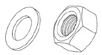
| 2. | M8 Stainless Steel Nuts | 6 |
| 3. | M8 Stainless Steel Flat Washers | 6 |
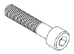
| 4. | M8 Stainless Steel 316 Hex Socket Cap Screws | 6 |
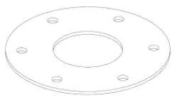
| 5. | Stainless Steel 316 Securing Plate | 1 |
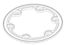
| 6. | Rubber Seal | 1 |
| 7. | 13mm Spanner/ Wrench | 1 |
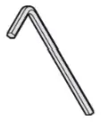
| 8. | 8mm Allen Key | 1 |
Appearance of components
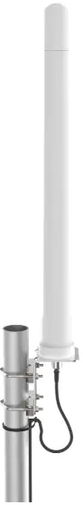
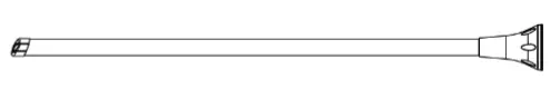
- Antenna Unit

- M8 Nut and Washer

- M8 Hex Socket Cap Screw

- Stainless Steel 316 Securing plate

- Rubber Seal

- 13mm Spanner/Wrench

- 8mm Allen Key


Tools Required
- 8mm Drill Bit/ Hole saw for cables

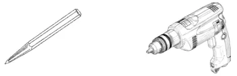
- Centre Punch and Drilling Machine

- Drilling Template
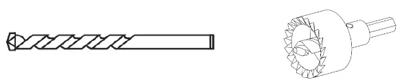
(Available on www.poynting.tech/downloads)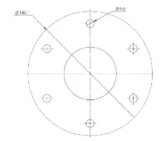
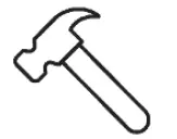
- Hammer

- Safety Goggles

Introduction
This User Guide provides information on the installation instructions of the Omni-directional antenna (A-OMNI-0900).
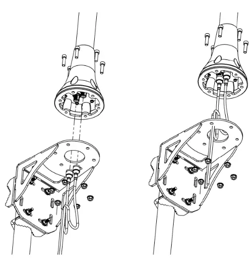
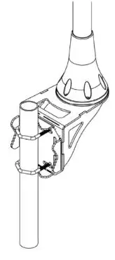
Antenna Configuration 1
Pole mount with optional bracket (BRKT-090) Exploded View
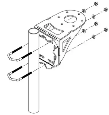
Note
Place the rubber seal at the bottom of the antenna and then connect the cable(s) to the antenna before attaching it to the bracket.
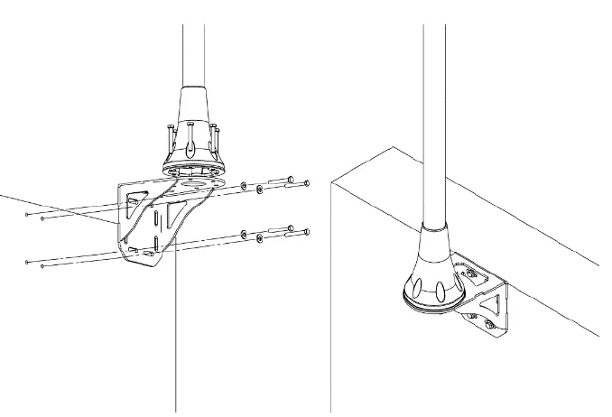
Antenna Configuration 2
Wall mount with optional bracket (BRKT-090). Exploded View
Note
Place the rubber seal at the bottom of the antenna and then connect the cables) to the antenna before attaching it to the bracket.
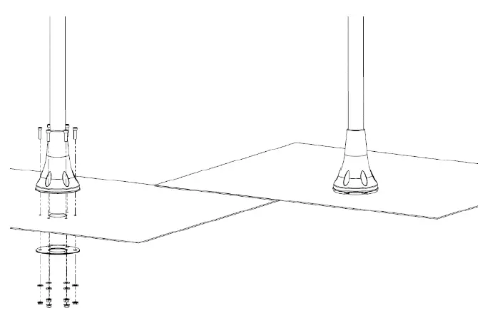
Antenna Configuration 3
Surface mount with supplied fastening plate. Exploded View
Note
Place the rubber seal at the bottom of the antenna and then connect the cables) to the antenna before attaching it to the bracket. Download the drilling template from www.poynting.tech/downloads.
Antenna mounting Precautions
- Place the antenna at the highest point of the vessel and ensure that there are not any surrounding obstructions to the antenna.
- In order to avoid communication interference, ensure that the antenna is placed at least 0.5m away from other antennas and metal objects.
- Avoid installing the antenna near the vessel’s chimney, as the smoke and soot emitted by the chimney can obstruct the signal level achieved by the antenna.
- Install the antenna away from the vessel’s heat sources and flammable gases.
Cable Routing
- Survey the planned cable route and look for any blocked passages. Consider alternate routes to find the best available path. Always keep the cables as short as possible to make sure that minimum cable losses are achieved.
- Note: Take advantage of any existing cable channels. e.g., wiring conduits to route the cables.
- Avoid running cables through components or sharp apertures that may cause excessive chafing. Doing so may erode the jacket and break signal continuity. Also, avoid kinking, pinching, or twisting a cable during a run.
- Use cable ties to secure the antenna cables. When handling the antenna cables, it is essential you follow these basic rules:
- Never pull on the cable connectors; pull only on the cable.
- Never run cables in a manner that interferes with the driver’s ability to safely operate the boat.
- Tighten the connectors and ensure that the cables don’t rattle loose.
Cable Connection
Note
Ensure that all RF connections made outdoors are adequately waterproofed. Waterproof connector boots are recommended.
Case 1: Router with two LTE ports (2×2 MIMO)
- If you are using an antenna variant with two LTE cables, connect the antenna cable labelled Cell (Main) to the respective Cell (Main) connector of your router. Similarly, connect the antenna cable labelled Cell (Aux/Div) to the respective Cell (Aux/Div) connector of your router.
- If you are using an antenna variant with four LTE cables, use one of the antenna diversity cable pairs. Use either the antenna cables labelled Cell 1 (Main) & Cell 1 (Aux/Div) or the antenna cables labelled Cell 2 (Main) & Cell 2 (Aux/Div) to connect to your router.
- If you have two routers that have two LTE ports each, you can either use an antenna variant with two LTE cables (you will need two) or use an antenna variant with four LTE cables. If you are using antennas with two LTE cables, connect the antenna diversity cable pairs such that one antenna’s Cell (Main) and Cell (Aux) cables are connected to one router’s Cell (Main) and Cell (Aux/Div) ports and the other antenna’s Cell (Main) and Cell (Aux/Div) cables are connected to the other router’s Cell (Main) and Cell (Aux/Div) port.
If you are using an antenna with four LTE cables, split the antenna diversity cable pairs such that one router is connected to the antenna cables labelled Cell 1 (Main) and Cell 1 (Aux/Div) and the other router is connected to the antenna cables labelled Cell 2 (Main) and Cell 2 (Aux/Div).
Case 2: Router with four LTE ports (4×4 MIMO)
- If you are using an antenna variant with four LTE cables, connect the antenna cable labelled Cell 1 (Main) to the respective Cell 1 (Main) connector of your router. Similarly, connect the antenna cable labelled Cell 2 (Main) to the respective Cell 2 (Main) connector of your router.
Next, connect the antenna cable labelled Cell 1 (Aux/Div) to the respective Cell 1 (Aux/Div) of your router. Similarly, connect the antenna cable labelled Cell 2 (Aux/Div) to the respective Cell 2 (Aux/Div) port of your router. - If you have an antenna variant with two LTE cables, you will need to purchase or add another similar antenna with two LTE cables. Connect the antenna diversity cable pairs such that one antenna’s Cell (Main) and Cell (Aux) cables are connected to your router’s Cell 1 (Main) and Cell 1 (Aux/Div) ports and the other antenna’s Cell (Main) and Cell (Aux/Div) cables are connected to Cell 2 (Main) and Cell 2 (Aux/Div) ports of your router.
Note
- Cell 1 (Main) and Cell 2 (Main) antenna cables are connected to the top antenna elements.
- Cell 1 (Aux/Div) and Cell 2 (Aux/Div) antenna cables are connected to the bottom antenna elements.
SAFETY
- If you are installing an antenna for the first time or unsure about how to install your antenna, obtain the help of a professional installer.
- Carefully survey the installation site before installation to locate secure handholds, dangerous conditions and the safest and most convenient placement for ladders if necessary.
- The antenna may not be used as a climbing or pulling device.
- Considerations must be taken when mounting the antenna that people do not hang or pull on it.
- When installing your antenna, remember:
- Do not install on a wet or windy day or when there is lightning or thunder in the area.
- Wear shoes with rubber soles and heels, protective clothing (long sleeve shirt or jacket) and rubber gloves.
- Avoid installation while under the influence of drugs, alcohol or medication.
- Make sure that any loose-fitting jewelry or clothing is secured and tie back long hair as they can get caught in moving parts during installation.
- If the antenna assembly starts to fall, get away from it and let it fall to avoid harming yourself.
When drilling remember
- Use safety goggles when drilling the holes.
- Avoid using bits that are dull, bent or damaged.
- Be aware of where your fingers are in relation to the drill bit when using the drilling machine.
- To stop the drilling machine, let the drill chuck come to a complete stop on its own. Do not grasp the chuck in an attempt to stop the drill bit.
- Avoid awkward hand positions where a sudden slip could cause a hand to move into the drill bit or cutting tool.
CAUTION
Antennas must be installed to provide a separation distance of at least 20cm from all persons so as to comply with SAR (Specific Absorption Rate) RF Exposure requirements.
European Waste Electronic Equipment Directive 2002/96/EC Please ensure that old waste, electricals and electronics are recycled.
Directive 2011/65/EU (RoHS 3) This product is fully compliant with the RoHS 3 directive.
South Africa
- Unit 4, N1 Industrial Park
- Landmarks Ave
- Samrand, 0157
- South Africa
- Tel: +27 12 657 0050
- [email protected].
USA
- 1804 Owen Court,
- Suite 104, Mansfield,
- TX 76063
- Tel: +1 817 533-8130
- [email protected].
Europe
- Kronstadler Straße 4,
- 81677 München
- Germany
- Tel: +49 89 2080 265 38
- Mob.: +49 176 529 733 50
- [email protected].


