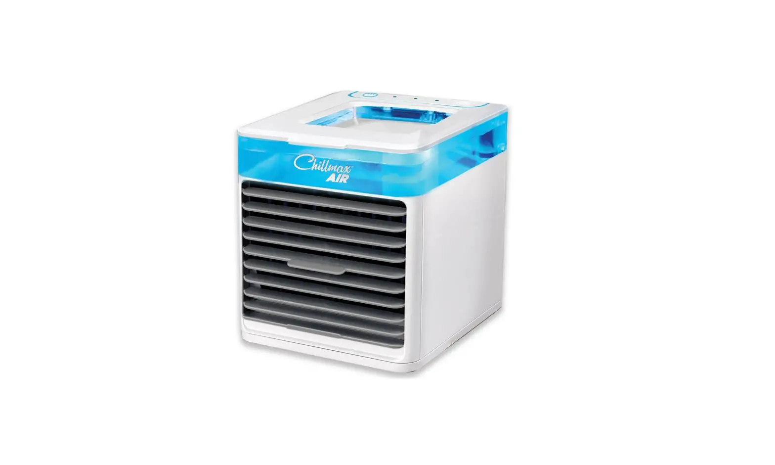
CHILL-MAX BEF-02 Chillmax Air Pure Chill User Manual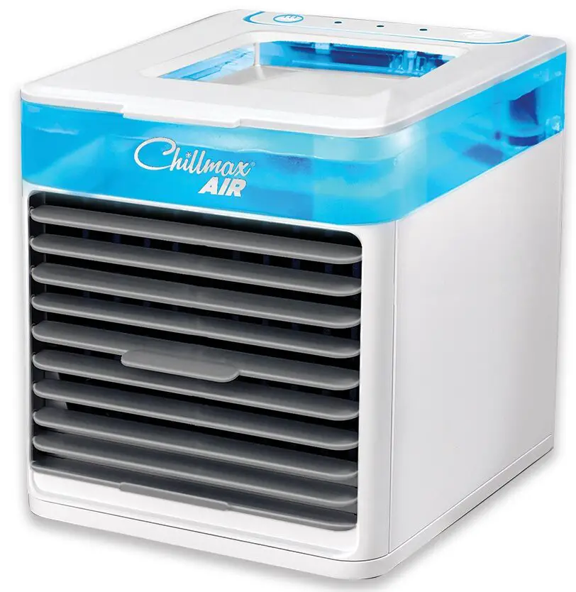
SPECIFICATIONS
| Model | BEF-02 | BEF-04 – 1 pump | BEF-05 – 1 pump | BEF-075 – 1 pump |
| BEF-04 – 2 pumps | BEF-05 – 2 pumps | BEF-075 – 2 pumps | ||
| BEF-075 – 3 pumps | ||||
| Cooling distance (ft.) | 75 | 150 | 225 | 350 |
| Pump flow(GPH) | 250 head pressure 0’60 head pressure 26’ | 50 | 50 | 50 |
| Compressor power (HP) | 1/3 | 1/3 | 1/2 | 3/4 |
| Voltage (V) – 60Hz | 120 | 120 | 120 | 120 |
| Plug type | NEMA 5-15P | NEMA 5-15P | NEMA 5-15P | NEMA 5-15P |
| Amps (A) – chiller (Running) | 5.5 | 7.0 | 8.0 | 9.5 |
| Min. circuit Ampacity (A) – chiller | 7.86 | 10.5 | 14.5 | 13.5 |
| Max. circuit Ampacity (A) – chiller | 15.0 | 15.0 | 25.0 | 20 |
| Amps (A) – circuit Ampacity (A) circulation motor/pump (Running) | 1.0 | 6.0 | 6.0 | 6.0 |
| Recommended circuit Ampacity (A) circulation motor/pump | 10 | 10.0 | 10.0 | 10.0 |
| 15.0 | 15.0 | 15.0 | ||
| 20.0 | ||||
| Refrigerant | R134a | R134a | R134a | R134a |
| Refrigerant capacity (oz.) | 9.25 | 17.0 | 11.5 | 19.5 |
| Normal refrigeration operating pressure (PSI) | 18 (low)135 (high) | 18 (low)135 (high) | 18 (low)135 (high) | 18 (low)150 (high) |
| BTUs/H (evap. @ 80oF) | 2560 | 3282 | 4080 | 6138 |
| Dimensions W x D x H (including pump and motor) | 16.5″ x 20″ x 20″ | 20.75″ x 23.5″ x 30.0″ | 20.75″ x 23.5″ x 30.0 | 20.5″ x 23.5″ x 30.0″ |
| 27,25″ x 23.5″ x 30.0″ | 27,25″ x 23.5″ x 30.0″ | 27,25″ x 23.5″ x 30.0″ | ||
| 34,0″ x 23.5″ x 30.0″ | ||||
| Weight (lbs.) | 61 | 121 | 132 | 149 |
| 136 | 147 | 164 | ||
| 180 | ||||
| Water bath capacity (US gal) | 4.5 | 17 | 17 | 17 |
HANDLING AND INSTALLATION
- Unpack the unit close to the installation area.
- Inspect the unit to make sure there is no apparent damage.
- Cautiously position the unit into the wanted position. Two(2) person are required to lift the unit.
NOTE: Do not move the unit without lifting it. Damage could occur to the legs of the unit if pushed.
NOTE: Do not lift any unit by the refrigeration lines or components. Please use designated handles.
NOTE: For BEF 075, the shroud must be removed to access the lifting handles. Make sure that the shroud is properly secured once the placement is completed.
PLACEMENT
- It is not advised to place a power pack on top of a walk-in cooler.
- It is not advised to place a power pack outside without protections.
- Always make sure a minimum clearance of 24 inches around and above the power pack. This is necessary for proper air flow and servicing.
- Ambient temperature ranges from 60°F to 85°F for all models.
- Make sure the unit is installed in a properly ventilated area.
- Unit must be connected to a ground fault circuit breaker.
- Power pack and pump must have their own dedicated electrical circuit.
BEF-02 INSTALLATION
- Clamp and insulate both glycol lines to the pump outlet and to the unit return fitting.
- Clean the reservoir.
- Fill the reservoir with CBS propylene glycol solution (mixed 2 parts water to 1 part glycol).
- Place the cover on the unit.
- Plug the pump in the electrical box on the unit.
- Plug the unit to an appropriate electrical circuit. This task should be executed by a professional electrician in compliance with national electrical standards.
- Inspect the unit for any leakage.
- Glycol temperature should be adjusted to 27°F. Set point should be reached within a few hours
NOTE: To adjust the glycol temperature, please see section 2.4.
BEF-04, BEF-05 AND BEF-075 INSTALLATION
- Remove the upper deck from the unit.
- Clean the reservoir and remove any dust or contaminant.
- Connect the overflow fitting to a proper external reservoir or drain.
- Clamp and insulate both glycol lines to the pump outlet and to the unit return fitting. Repeat this step for each pump.
- Fill the reservoir with CBS propylene glycol solution (mixed 2 parts water to 1 part glycol).
- Place back the upper deck on the unit.
- Plug the unit and the pump to an appropriate electrical circuit. This task should be executed by a professional electrician in compliance with national electrical standards.
- Inspect the unit for any leakage.
- Glycol temperature should be adjusted to 27°F. Set point should be reached within a few hours.
NOTE: To adjust the glycol temperature, please see section 2.4.
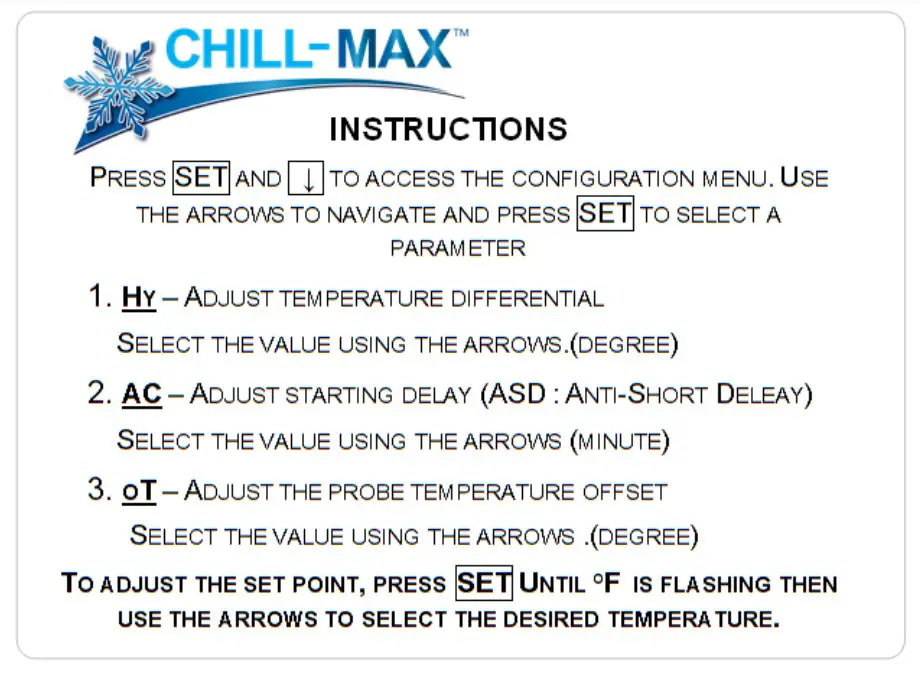
ADJUSTING THE TEMPERATURE CONTROLLER
Instructions for all models
MAINTENANCE
- Check the glycol level each month to make sure it’s still within 0.5 inch below the overflow fitting.
- If the level is too low, add CBS propylene glycol solution (mixed 2 parts water to 1 part glycol).
- If there are any signs of ice in the unit, give time to the ice to melt and change all the solution with a fresh solution mixed as indicated in the installation instructions.
- Drain and replace the propylene glycol solution every 24 months.
- Clean the condenser every thirty (30) days. Be careful to not damage the aluminum fins. NEVER brush sideways.
SERVICING
If you have any problem with the unit, please refer to section 5 to identify the cause of the problem.
REPLACE CIRCULATION PUMP – BEF-02
- Unplug the pump and the unit from their electrical circuit.
- Pinch the glycol lines to avoid any dumping.
- Disconnect the glycol line from the pump.
- Remove the pump mounting screws (4).
- Replace the defective circulation pump by a new one.
- Tighten the mounting screws (4).
- Connect the glycol line and secure with a stainless steel ear clamp.
- Release the glycol lines.
- Reconnect the unit and pump to their electrical circuit.
REPLACE CIRCULATION PUMP – BEF-04, BEF-05 & BEF-075
- Unplug the motor and the unit from their electrical circuit.
- Pinch the glycol lines to avoid any dumping.
- Remove the pump insulation. Disconnect the glycol line from the pump.
- Remove the pump mounting screw (1).
- Replace the defective circulation pump and the damper coupling by new ones.
- Tighten the pump mounting screw (1).
NOTE: Make sure the pump is properly aligned with the damper coupling and the motor. - Connect the glycol lines and secure with a stainless steel ear clamp.
- Release the glycol lines.
- Reconnect the unit and the motor to their electrical circuit.
REPLACE MOTOR OF CIRCULATING PUMP – BEF-04, BEF-05 & BEF-075
- Unplug the motor and the unit from their electrical circuit.
- Remove the pump mounting screw (1).
- Remove the motor mounting screws (4).
- Replace the defective motor pump and the damper coupling by new ones.
- Tighten the motor mounting screws (4).
- Tighten the pump mounting screw (1).
NOTE: Make sure the pump is properly aligned with the damper coupling and the motor. - Reconnect the unit and the motor to their electrical circuit.
REPLACE TEMPERATURE CONTROLLER
NOTE: Before doing any work on electrical components, disconnect the unit from its electrical circuit.
- Dismantle the temperature controller housing.
TIP: Keep pictures and notes of the wire connections. - Remove wire connectors using a small slotted screwdriver.
- Slide off the plastic retainer by applying pressure with a small screw driver on each side. Pull out the temperature controller of the housing.
- Connect wires to the correct numbers on new thermostat and reassemble into housing.
NOTE: Firmly tighten the wire clamp screws. Refer to section 0 for the correct wiring. - Re-install the temperature controller and the plastic retainer.
- Re-install the housing on the support plate.
- Reconnect the unit to the electrical circuit.
- Adjust the temperature controller, Refer to section 2.4.
REPLACE TEMPERATURE CONTROLLER RELAY
NOTE: Before doing any work on electrical components, disconnect the unit from its electrical circuit.
- Dismantle the temperature controller housing.
TIP: Keep pictures and notes of the wires connections. - Remove wire connectors using long nose pliers.
- Remove relay mounting screws (2).
- Connect wires to correct position on new relay and tighten the mounting screws (2).
TROUBLESHOOTING
| OBSERVATION | CAUSE | FIX |
| Compressor doesn’t start | Temperature controller or relay failure (temperature controller housing) | Check the output voltage on each components (2) and replace thedefective part |
| Relay, overload or start capacitor failure (on the compressor) | Replace relay and/or overload and/or start capacitor | |
| Input voltage is too low | Check input voltage, refer to specifications of the unit | |
| Compressor failure | Replace compressor (Has to be performed by a certified refrigerationexpert) | |
| Compressor runs but never reaches set point | Set point is too low | Adjust set point to a minimum of 27°F |
| Temperature probe is not properly connected or installed | Temperature probe must be in the bottom of the reservoir and in no contact with any metallic part | |
| Refrigerant leak | Perform a leak test and repair the leak. Vacuum flush the refrigerant and fill with proper quantity. (Has to beperformed by a certified refrigeration expert) | |
| Dirty condenser | Disconnect the unit. Clean the condenser using degreaser and water.Do not spill liquid on any electrical component. Be careful to not damage the aluminum fins of the condenser. | |
| Dusty condenser | Disconnect the unit. Clean the condenser with pressurized air. | |
| Condenser fan malfunction | If the compressor runs but not the fan, replace the fan motor. | |
| Frozen glycol | Inadequate water/glycol mixture | Check mixture with a refractometer. Mixture must be between 5°F and 20°F |
| Compressor never stops due to malfunction of the temperature controller | Check if temperature probe is properly connected, if required replace temperature controller | |
| No outflow of the circulation line | Circulation line blocked | Inspect and locate blockage. Clean the lines. |
| Pump failure | Replace the pump | |
| Damper coupling broken | Replace damper coupling |
ELECTRICAL WIRING DIAGRAMS
NEVER modify the electrical circuit of the unit. If required, ONLY use 14 AWG wire. Electrical repairs must be done by a professional electrician.
ELECTRICAL DIAGRAM BEF-02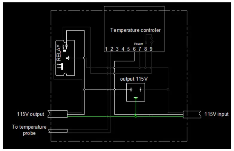
ELECTRICAL DIAGRAM BEF-04, BEF-05 AND BEF-075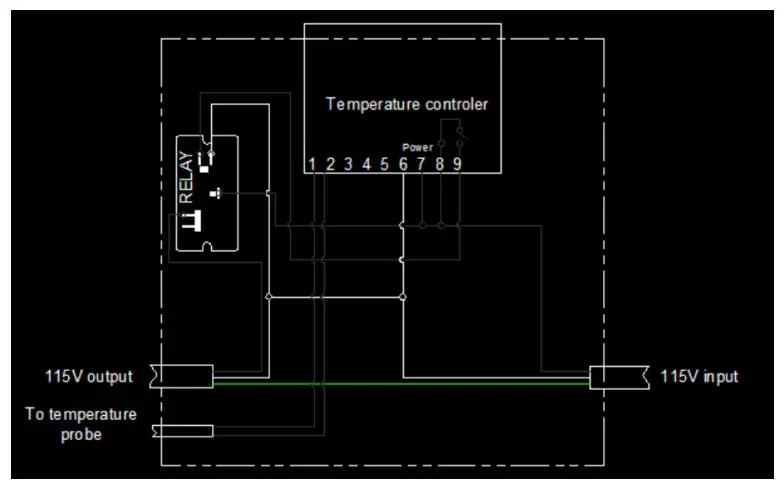
REPLACEMENT PARTS LIST
| Component | Part Number | BEF-02 | BEF-04 | BEF-05 | BEF-075 |
| Temperature controller | XR02CX | X | X | X | X |
| Temperature controller relay | RPF2BF7 | X | X | X | X |
| Agitator pump | SPC42 | X | |||
| Motor (1/3 HP) | MP551740 | X | X | X | |
| Circulation pump | MP000585 | X | X | X | |
| Foam pump jacket | MP000499 | ||||
| Dumper coupling KIT | MP000448 | X | X | X | |
| BEF-02 Condensing unit | AEA4440-YXAGK | X | |||
| BEF-04 Condensing unit | AE4450Y-AA1ADA | X | |||
| BEF-05 Condensing unit | AKA7437YXAXA | X | |||
| BEF-075 Condensing unit | AJA7455YAADS | X | |||
| BEF-02 Relay | K71-36 | X | |||
| BEF-04 Relay | K71-41 | X | |||
| BEF-05 Relay | K71-02 | X | |||
| BEF-075 Relay | K71-13 | X | |||
| BEF-02 Start capacitor | K146-55 | X | |||
| BEF-04 Start capacitor | K146-55 | X | |||
| BEF-05 Start capacitor | K146-52 | X | |||
| BEF-075 Start capacitor | K146-04 | X | |||
| BEF-02 Compressor | AE4440Y-AA1A | X | |||
| BEF-04 Compressor | AE4450Y-AA1A | X | |||
| BEF-05 Compressor | AKA4476YXA | X | |||
| BEF-075 Compressor | AJA7461YXA | X | |||
| BEF-02 Fan motor | 9W115 | X | |||
| BEF-04 Fan motor | 810-10095 | X | |||
| BEF-05 Fan motor | 810-10095 | X | |||
| BEF-075 Fan motor | 810M035B69 | X | |||
| BEF-02 Overload protector | K90-56 | X | |||
| BEF-04 Overload protector | K90-61 | X | |||
| BEF-05 Overload protector | K90-23 | X | |||
| BEF-075 Overload protector | K90-38 | X |