![]() SCI Short Circuit Isolator
SCI Short Circuit Isolator
Instruction Manual
SCI Short Circuit Isolator
NOTICE TO THE INSTALLER
This manual provides an overview and the installation instructions for the Short Circuit Isolator SCI. This SCIis only compatible with addressable fire systems that utilize the Potter/Nohmi addressable protocol.
All terminals are power limited and should be wired in accordance with the requirements of NFPA 70 (NEC) and NFPA 72 (National Fire Alarm Code). Failure to follow the wiring diagrams in the following pages will cause the system to not operate as intended. For further information, refer to the control panel installation instructions.
The module shall only be installed with listed control panels. Refer to the control panel installation manual for proper system operation.
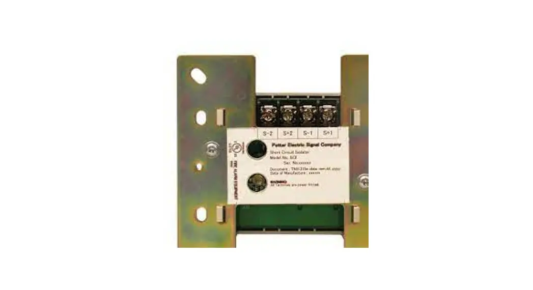
Description
The SCI is used to provide additional reliability for a fire protection system by isolating a segment of an SLC loop in which a short circuit has occurred. This makes it possible for the remainder of the loop to provide normal monitoring functions.
SCI employs one red LED to indicate the status. In normal condition, the LED is deactivated. When the short circuit is happened, SCI will cut off the short circuit and turn on the LED. Once the short is removed, the SCI will automatically restore the loop to the intended operating condition.
Wiring diagram
- Class B (Style 4) Wiring
*Class B (Style 4) Wiring- Resistance of wiring connected to the SCI must not exceed 10 ohms.
- A maximum of 50 addressable detectors and addressable modules can be connected to a SCI.
 Figure 1: Class B (Style 4) Wiring Diagra
- Class A (Style 6) Wiring
*Class A (Style 6) Wiring- The wiring resistance between two Short Circuit Isolators must not exceed 10 ohms.
- A maximum of 50 addressable detectors and addressable modules can be connected between any two SCIs.Figure 2: Class A (Style 6) Wiring Diagram
 Figure 2: Class A (Style 6) Wiring Diagram
- Class A (Style 7) Wiring
Note: For Class A (Style 7), each device close nippled with the SCI and all the wirings between SCIs and addressable devices must be installed in conduits.
* Class A (Style 7) Wiring- The wiring resistance between two Short Circuit Isolators mustnot exceed 10 ohms.
 Figure 3: Class A (Style 7) Wiring Diagram
- The wiring resistance between two Short Circuit Isolators mustnot exceed 10 ohms.
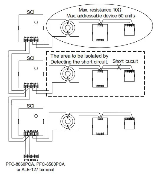 Figure 1: Class B (Style 4) Wiring Diagra
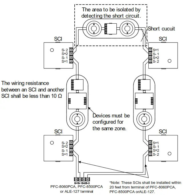 Figure 2: Class A (Style 6) Wiring Diagram
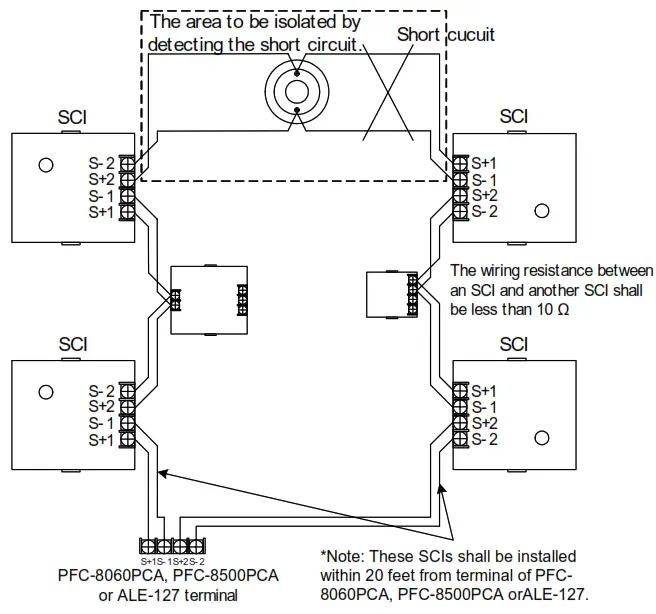 Figure 3: Class A (Style 7) Wiring Diagram
Note:
- SLC loop wiring (S+1, S-1, S+2 and S-2) are power limited.
- Wiring for terminals S+1, S-1, S+2, S-2 are supervised.
- When multiple zones are configured to Notification Appliance Circuits (NACs), those NACs must be protected by SCIs per zone.
- All wiring is between #14 (2.08 mm ) (min.).
- Wire Preparation
Strip all wires 1/4 inch from their edges as follows: 2 ) (max.) and #22 (0.32 mm 2

Note:
a) Stripping too much insulation may cause ground fault
b) Stripping too little may cause a poor connection and subsequently an open circuit
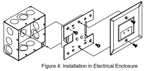
Installation Instruction
Specifications
| No. | Item | Specification |
| 1 | Rated voltage range of SLC input power (S+, S-) | 22.0 to 24.0V |
| 2 | Maximum SLC 24 VDC standby current (S+, S-) | 250pA |
| 3 | Maximum SLC 24 VDC active current (S+, S-) | 1.80mA |
| 4 | Internal Resistance | 0.10 |
| 5 | Wiring resistance or wiring after a SCI in Class B (style 4) | 100 |
| 6 | Wiring resistance or wiring between a SCI and another SCI in Class A (style6 and 7) | 100 |
| 7 | Maximum no. of SCI on an SLC loop in Class B style 4 | 16 units |
| 8 | Maximum no. of SCI on an SLC loop in Class A (style 6 and 7) | 64 units |
| 9 | Maximum no. of addressable device connected to a SCI | 50 units |
| 10 | Operating temperature range | 32 to 120-F (0 to 49°C) |
| 11 | Operating humidity range | 0 to 93% (non-condensing) |
| 12 | Dimensions | 4.17″(106mm) (H) x 4.17″(106mm) (W) x 1.14″(29mm) (D) |
| 13 | Applicable electrical box for installation | 2-1/2″(64mm)deep 2-gang box Standard 4″square box 1-1/2″(38mm)deep box |
These instructions do not purport to cover all the details or variations in the equipment described, nor provide for every possible contingency to be met in connection with installation, operation and maintenance.
Specifications subject to change without prior notification
For Technical Assistance contact Potter Electric Signal Company at 800-325-3936
Actual performance is based on proper application of the product by a qualified professional.
Should further information be desired or should particular problems arise, which are not covered sufficiently for the purchaser’s purpose, the matter should be referred to Potter-Nohmi or a distributor in your region.
![]() Potter Electric Signal Company, LLC
Potter Electric Signal Company, LLC
1609 Park 370 Place, Hazelwood, MO 63042 USA
Telephone: (866)956 -1211
URL: http://www.pottersignal.com
firealarmresources.com
TN51319e<0>
Effective 01.05, 2011


