
POTTER PAD100-IB Addressable Isolator Base
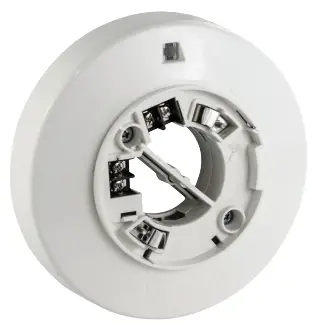
PAD100-IB Addressable Isolator Base
Features
- Isolator integrated into base
- Self restoring
- Red LED indication of short circuit
- Terminals accept 22 to 12 AWG wire sizes
- Supports Class A, Class X and Class B wiring
- Does not require SLC Loop address
- UUKL Listed for Smoke Control
Description
The Addressable Isolator Base 6” (PAD100-IB) comes with an integrated isolator module included. The base has a locking feature for the sensor that may be used or removed in the field. Once the head is removed, the isolator is accessible in the bottom of the unit.
The isolator will open the Signaling Line Circuit down stream when a short circuit is detected. This will provide devices between the control panel and the isolator to continue to operate. The short is indicated by a steady red LED and once the short is removed the unit will return to normal operation.
Technical Specifications
| Working Range for SLC | 24 VDC |
| active indicator | 1 LeD (red) |
| applicable SLC wiring style | Class a, B and X |
| Maximum number of paD100-IB per SLC Loop | 127 |
| Installation temperature range | 32°F to 120°F (0°C to 49°C) |
| Operating relative humidity range | 0% to 93% (Non-condensing) |
| Color | eggshell White |
| Dimensions (without detector) | Height: 0.75 in (19mm) Diameter: 6.3 in (166 mm) |
Detector Base Mounting
PAD100-IB should be mounted directly on the electrical box. The mounting holes are configured for a single gang, double gang, octagon or 4” square box. See Fig 1.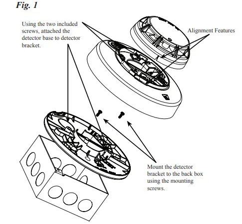
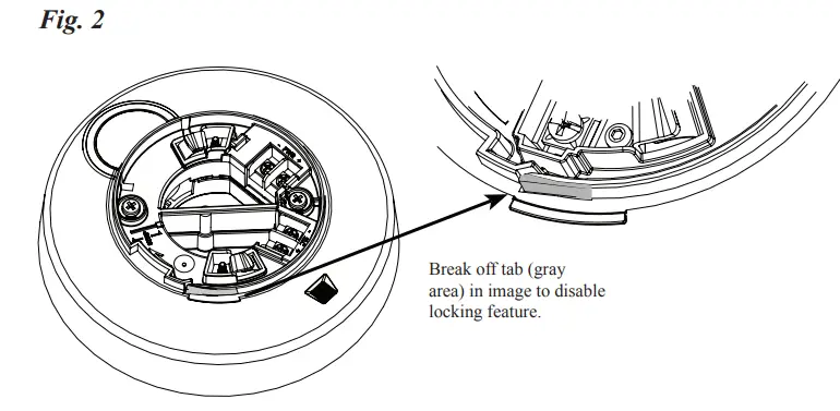
Locking Feature
Eliminate the Locking Feature
PAD100-IB include a locking feature that prevents removal of the detector and removal of the base cover without using a tool.
- To eliminate this feature, break off the locking tab (refer to Figure 2), and then install the detector. See Fig. 2.
 Removing of Detector Head from Base
 - To remove the detector from the base once the locking feature has been activated, insert a small screwdriver into the slot on the base to push the plastic tab while simultaneously turning the detector head counter-clockwise. See Fig. 3.

- To remove the base cover from the lower enclosure once the locking feature has been activated, insert a small screwdriver into the slot on the on the base to push the plastic tab while simultaneously turning the detector head counter-clockwise.
 Removing of Detector Head from Base
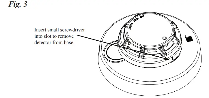
Ordering Information
| Model | Description | Stock No. |
| paD100-IB | addressable Isolator Base | 3992730 |
Potter Electric Signal Company, LLC
St. Louis, MO
Phone: 800-325-3936
www.pottersignal.com