![]() AIB
AIB
AddressABle IsolAtor BAse
Owner’s Manual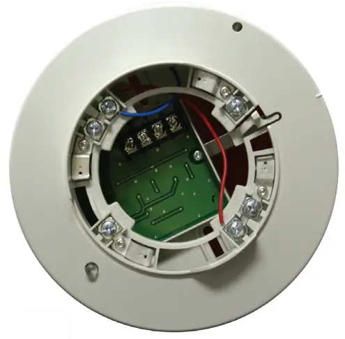
![]() Product includes a 5 year warranty
Product includes a 5 year warranty
Features
- Isolator integrated into base
- Self restoring
- Amber LED indication of short circuit
- Maximum standby current, 325 µA
- Maximum alarm current, 1.85 mA
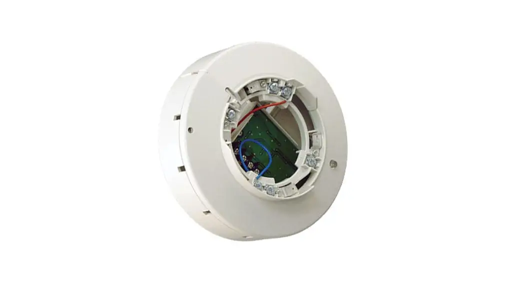
Description
The Addressable Isolator Base 6” (AIB) comes with an integrated isolator module included. The base has a locking feature for the sensor that may be used or removed in the field. Once the head is removed, the isolator is accessible in the bottom of the unit.
The isolator will open the Signaling Line Circuit down stream when a short circuit is detected. This will provide devices between the control panel and the isolator to continue to operate. The short is indicated by a steady amber LED and once the short is removed the unit will return to normal operation.
Detector Base Mounting
AIB should be mounted directly on the electrical box. The mounting holes are configured for a single gang, double gang, octagon or 4” square box.
Locking Feature
AIB include a locking feature that prevents removal of the detector and removal of the base cover without using a tool.
- To eliminate this feature, break off the locking tab (refer to Figure 1), and then install the detector.
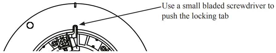
Figure 1. Eliminate the Locking Feature
- To remove the detector from the base once the locking feature has been activated, insert a small screwdriver into the slot on the base to push the plastic tab while simultaneously turning the detector head counter-clockwise (refer to Figure 2).
Figure 2. Removing of detector head from base
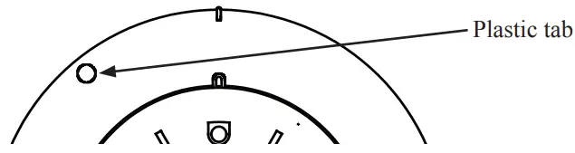
- To remove the base cover from the lower enclosure once the locking feature has been activated, insert a small screwdriver into the slot on the on the base to push the plastic tab while simultaneously turning the detector head counter-clockwise (refer to Figure 3).
Figure 3. Removing of base cover from the lower enclosure

Specifications
| No. | Item | AIB-6 | |
| 1 | Working voltage range for SLC | 22.0 to 24.0 V | |
| 2 | Standby current for SLC 1 | 325 pA | |
| 3 | Active current (Include indicator) | 1.85 mA D.C. (max.) | |
| 4 | Active indicator | 1 LED (yellow) | |
| 5 | Applicable SLC wiring style | NFPA Style 4,6 and 7 | |
| 6 | Resistance of wiring after an AIR in Style 4 | 10 a (max.) | |
| 7 | Resistance of wiring between an AIR and the next AIB in Style 6 or 7 | 10 si (max.) | |
| 8 | Maximum number of AIB per SLC Loop | Style 4 | Number of points of panel divided by 8 |
| Style 6 and 7 | Number of points of control panel | ||
| 9 | Maximum number of addressable devices connected to an AIB | 50 units | |
| 10 | Installation temperature range 2 | 32°F to 120°F (0°C to 49°C ) | |
| 11 | Operating relative humidity range | 0% to 93% (Non-condensing) | |
| 12 | Color | Eggshell White | |
| 13 | Height | 2.13 inches (54.4mm) | |
| Dimensions (without detector) | Diameter | 6 inches (150mm) | |
| (1)The standby current is the current that the device consumes when the device is in a non-activated condition and where no communication current is transmitted to the fire alarm control panel. (2)FHA with AIR should be installed under 120°F. (Installation temperature range of AIB is 32°C to 120°E) | |||
NOTICE
All specifications are subject to change without notice. For further information, contact Potter Electric Signal Company Technical Support.
MKT. #8830009 – REV C 06/13
firealarmresources.com
PRINTED IN USA


