 AIRZONE Aidoo KNX Controller
Product Information: Aidoo KNX Controller
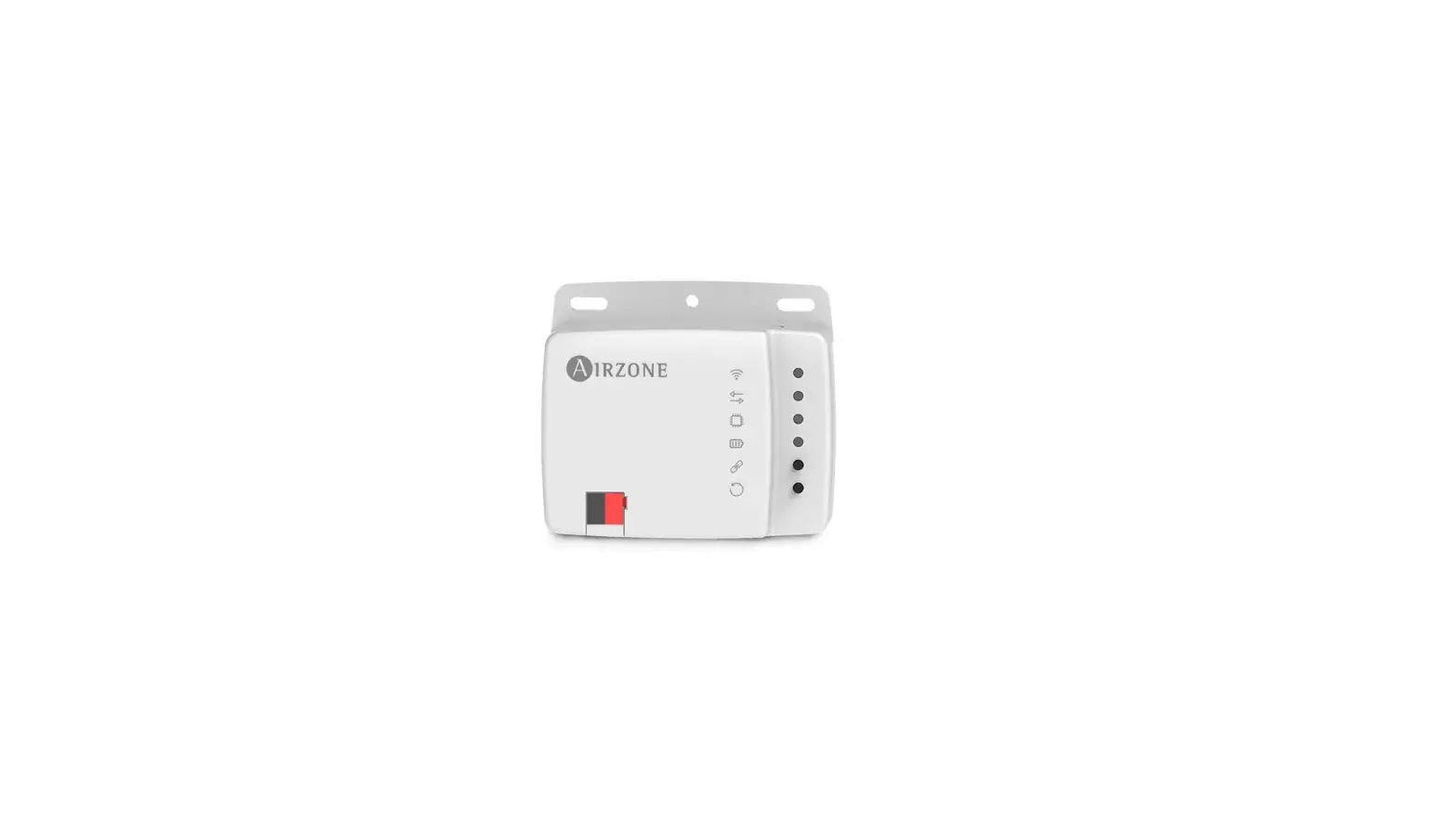
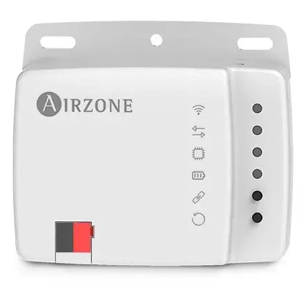
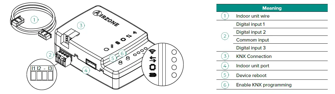
The Aidoo KNX Controller is a device that manages and integrates HVAC units in KNX TP-1 control systems. It is externally powered by the indoor unit and has a standard KNX connector for connecting to the KNX bus. The device features indoor unit wires, digital inputs, common input, KNX connection, indoor unit port, device reboot, and enable KNX programming.
Product Usage Instructions
Follow these instructions to use the Aidoo KNX Controller:
- Mount the device using screws or double-sided adhesive tape.
- Follow the instructions on the technical data sheet for connecting the device to the AC unit.
- Connect the Aidoo to the KNX TP-1 bus, following the color code.
- Configure and set up the device through ETS tool using the product database downloaded from http://doc.airzone.es/producto/Gama_AZ6/Airzone/Aidoo/BBDD_AZAI6KNX.zip
- Use the default communication objects available in ETS for the Aidoo KNX device to control the AC unit’s on/off switch, operating mode, ventilation speed, and position of the slats.
- For your security and to protect the devices, strictly follow the directions outlined in the manual and the environmental policy for the Airzone System and communications.
Warnings and Environmental Policy
Precautions
For your security and to protect the devices, follow these instructions:
- Strictly follow the directions outlined in the manual.
- Follow the instructions on the technical data sheet for connecting the device to the AC unit.
- Connect the Aidoo to the KNX TP-1 bus, following the color code.
Environmental Policy
 General requirements: Strictly follow the directions outlined in this manual for the Airzone System and communications. Do not dispose of this equipment in the household waste. Electrical and electronic equipment contain substances that may damage the environment if they are not handled appropriately. The symbol of a crossed-out waste bin indicates that electrical equipment should be collected separately from other urban waste. For correct environmental management, it must be taken to the collection centers provided for this purpose, at the end of its useful life. The equipment’s components may be recycled. Act in accordance with current regulations on environmental protection. If you replace it with other equipment, you must return it to the distributor or take it to a specialized collection center. Those breaking the law or by-laws will be subject to such fines and measures as are laid down in environmental protection legislation.
General requirements
Strictly follow the directions outlined in this manual:
- This system must be installed by a qualified technician.
- Verify that the units to be controlled have been installed according to the manufacturer’s requirements and operate correctly before installing the Airzone System.
- Locate and connect all the devices of the installation in accordance with the electronic regulations in force.
- Verify that the air conditioning installation to be controlled is in accordance with the regulations in force.
- Perform all the connections with total absence of power supply.
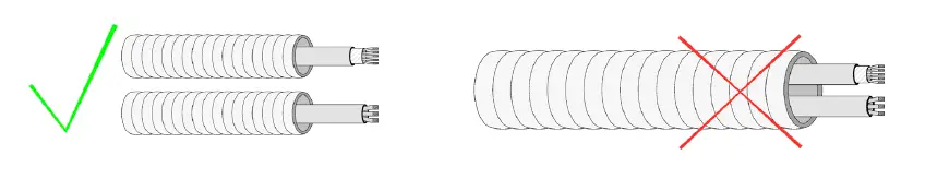
- Do not place the system bus close to lines of force, fluorescent lights, LED lamps, motors, etc. It might cause interference on the communications.

- Respect the connection polarity of each device. A wrong connection may seriously damage the product.
Introduction
Device to manage and integrate HVAC units in KNX TP-1 control systems.
Externally powered by the indoor unit. Features:
- Control of the parameters of the unit.
- KNX Control.
- KNX standard data.
- 3 digital inputs.
- Easily configurable from ETS.
- Communication errors detection.

Assembly
The device can be mounted using screws or double-sided adhesive tape (included with the product).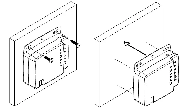
Connection
To connect the device to the AC unit, follow the instructions on the technical data sheet that comes with the Aidoo. It has a standard KNX connector for connecting to the KNX bus. Connect the Aidoo to the KNX TP-1 bus, following the color code.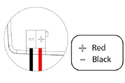
Configuration
This device is totally compatible with KNX, so you can configure it and set it up through ETS tool. To do this, download the product database at:
http://doc.airzone.es/producto/Gama_AZ6/Airzone/Aidoo/BBDD_AZAI6KNX.zip The installation of the database in the ETS tool is carried out following the usual procedure for importing new products.
Communication objects
The Aidoo KNX device has a series of communication objects available for configuration by default (see the Default communication objects section). If you wish to use all the communication objects contained in this device, go to the Parameters tab in order to enable them (see the Configuration Parameters section for more information).
IMPORTANT: The number of functionalities that can be controlled by the different communication objects offered by the Aidoo KNX device will depend on the particular AC unit being controlled. To view all the communication objects available on the Aidoo KNX device, please go to Annexes – Index – Communication Objects for more information.
DEFAULT COMMUNICATION OBJECTS
The default communication objects available in ETS for the Aidoo KNX device are:
| Object number | 1: Control On/Off | |
| Description | This allows you to switch the AC unit on or off | |
| Values | 0 -> Off | 1 -> On |
| Type of access to the Bus | Write | |
| Data point identification
Object number | 1.001 (DPT_Switch)
2: Control Mode |
Note: You can configure the object type in the Fan Configuration section, under the Parameters tab in ETS. By default it is configured as Datapoint 5.001 (percentage control). See the Configuration Parameters – Fan Configuration section for more information.
Note: Configure the object type in the Vanes Up-Down configuration section, under the Parameters tab in ETS. By default it is configured as Datapoint 5.001 (percentage control). See the Configuration Parameters – Vanes Up-Down configuration section for more information.
| Object number | 51: Status On/Off | |
| Description | This displays the status of the AC unit (on or off) | |
| Valores disponibles | 0 -> Off | 1 -> On |
| Tipo de acceso al bus | Reading | |
| Identificación Datapoint | 1.001 (DPT_Switch) | |
| Object number | 52: Status mode | |
| Description | Position | |
| Values | 0 -> Auto 1-> Heat 3 -> Cool | 9 -> Fan 14 -> Dry |
| Type of access to the Bus | Reading | |
| Data point identification | 20.105 (DPT_ Hvaccontrmode) | |
| Object number | 60: Status Fan speed / 3 speed | |
| Description | This displays the AC unit’s ventilation speed | |
| Values | 33% -> Speed 1 67% -> Speed 2 100% -> Speed 3 | 1 -> Speed 1 2 -> Speed 2 3 -> Speed 3 |
| Type of access to the Bus | Reading | |
| Data point identification | 5.001 (DPT_Scalling) | 5.010 (DPT_Enumerated) |
Note: Configure the object type in the Vanes Up-Down configuration section, under the Parameters tab in ETS. By default it is configured as Datapoint 5.001 (percentage control). See the Configuration Parameters – Vanes Up-Down configuration section for more information.
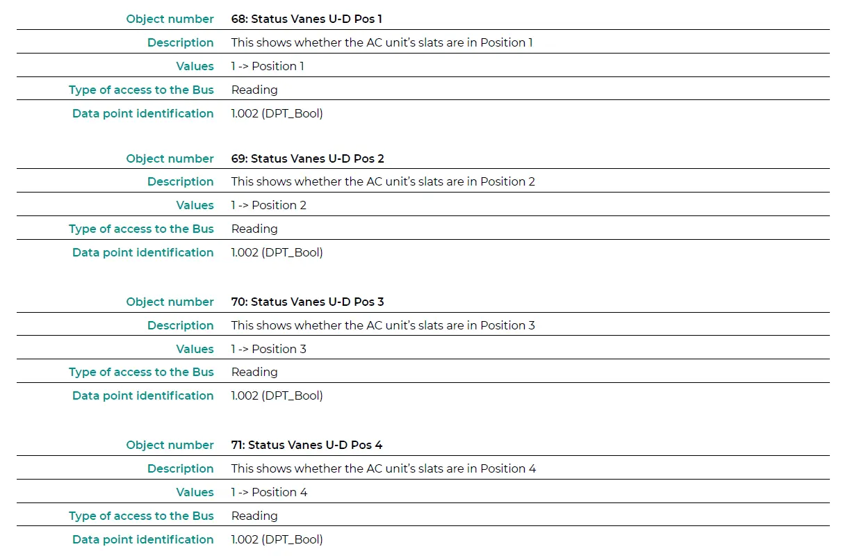
| Object number | 66: Status Vanes U-D/5Pos | |
| Description | This displays the position of the AC unit’s slats | |
|
Values | 20% -> Position 1 40% -> Position 2 60 % -> Position 3 80% -> Position 4 100% -> Position 5 | 1 -> Position 1 2 -> Position 2 3 -> Position 3 4 -> Position 4 5 -> Position 5 |
| Type of access to the Bus | Reading | |
| Data point identification | 5.001 (DPT_Scalling) | 5.010 (DPT_Enumerated) |
Note: Configure the object type in the Vanes Up-Down configuration section, under the Parameters tab in ETS. By default it is configured as Datapoint 5.001 (percentage control). See the Configuration Parameters – Vanes Up-Down configuration section for more information.
CONFIGURATION PARAMETERS
The Aidoo KNX device has a series of communication objects that can be enabled for use via the Parameters tab in ETS.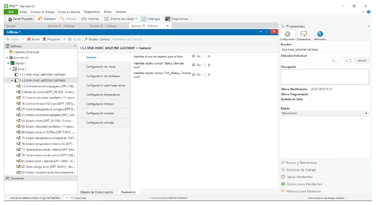
General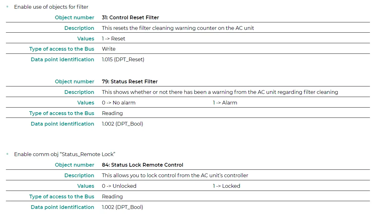


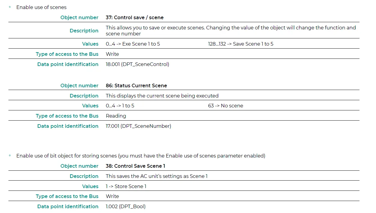
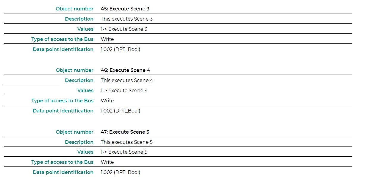
Enable use of scenes
Scene 1 / 2 / 3 / 4 (you must have the Enable use of scenes parameter enabled). Select the scene ID (values available from 0 to 63). If you wish to configure each scene from ETS, activate the System Preset parameter and configure the values of each parameter for the desired AC unit:
- Value for On-Off: Select if you want to turn the AC unit on/off, or if you do not want to carry out any action.
- Value for mode: Select if you want to change the AC unit’s operating mode, or if you do not want to carry out any action.
- Value for fan speed: Select if you want to change the AC unit’s ventilation speed, or if you do not want to carry out any action.
- Value vanes U-D: Select if you want to modify the position of the AC unit’s slats, or if you do not want to carry out any action.
- Value for Setpoint: Select if you want to change the AC unit’s setpoint temperature (16 – 30°C), or if you do not want to carry out any action.
Inputs configuration
Enable the use of the Aidoo KNX digital inputs:
- Input 1: Communication objects 87 and 88.
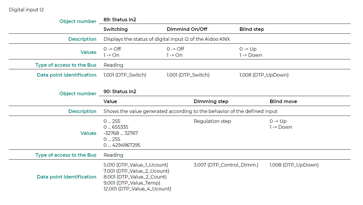
- Input 2: Communication objects 89 and 90.
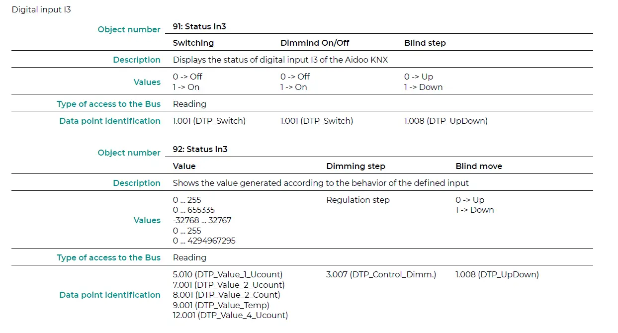
- Input 3: Communication objects 91 and 92.
The objects will behave differently depending on the configuration of each input.
Parameters available for configuring each digital input:
- Contact type. Defines the contact logic as Normally Open or Normally Closed.
- Debounce time. Select the debounce time (in milliseconds) required for the system to recognize there has been a change in the contact.
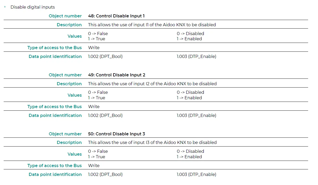
- Disabling input object. Select whether or not you want to enable the object that allows the input to be disabled if necessary (communication objects 48, 49 and 50). If yes, select whether you want to use Datapoint DPT 1.002 (0 = False) or DTP 1.003 (0 = Disable).
- Function. Select the digital input function of the Aidoo KNX:
- Switching
- Send telegram after bus recovery. Select the action to be performed on this digital input after bus recovery (after a power failure): no action, off (0), on (1) or current status.
- Sending delay after bus recovery. If an action is selected, indicate the time delay for sending the telegram (in seconds).
- Value on raising Edge (contact activated). Select the action to be sent to the associated communication object, if it produces a rising edge (activated input): no action, off (0), on (1) or toggle.
- Value on falling Edge (Contact deactivated). Select the action to be sent to the associated communication object, if it produces a falling edge (deactivated input): no action, off (0), on (1) or toggle.
- Cyclical sending. Select if you want cyclical sending to occur depending on the status of the digital input: never, always, when the output value is Off, or when the output value is On.
- Period for cyclical sending (s). If cyclical sending is selected, indicate the time period (in seconds) for this cycle.
- Dimming
- Send telegram after bus recovery. Select the action to be performed on this digital input after bus recovery (after a power failure): no action, off (0) or on (1).
- Sending delay after bus recovery. If an action is selected, indicate the time delay for sending the telegram (in seconds).
- Mode for short (long) operation. Select the action for a short operation to be sent on a rising edge (activated input): toggle, off/decrease (0) or on/increase (1). A press and hold will result in either an increasing step or a decreasing step.
- Increasing step. Select the percentage of the increasing step that will be sent for a long operation.
- Decreasing step. Select the percentage of the decreasing step that will be sent for a long operation.
- Short/long operation limit (ms). Defines the time that must elapse for the object to interpret that a long operation has occurred (in milliseconds).
- Cyclical sending period in long operation (0-No cyclical sending) (ms). Defines the time (in seconds) during which the long operation must be executed.
- Send telegram after bus recovery. Select the action to be performed on this digital input after bus recovery (after a power failure): no action, off (0) or on (1).
- Shutter/blind
- Send telegram after bus recovery. Select the action to be performed on this digital input after bus recovery (after a power failure): no action, increase (0) or decrease (1).
- Sending delay after bus recovery. If an action is selected, indicate the time delay for sending the telegram (in seconds).
- Operation. Select the action to be sent on a rising edge (activated input): increase (0), decrease (1) or toggle.
- Method. Select the operating method for the shutter/blind: step-move-step or move-step.
- Step-Move-Step. On a rising edge (activated input) a step telegram will be sent and the counter defined in “Short/long operation limit (ms)” (counter 1) will start. Note: No action will be taken if a falling edge (deactivated input) occurs during this time. If the rising edge is maintained for longer than the time defined in counter 1, a move telegram will be sent and a second counter, defined in “Vanes adjustment time (ms)” (counter 2), will start. If a falling edge (deactivated input) occurs during the time specified in this second counter, a step telegram will be sent. Note: No action will be taken if a falling edge (deactivated input) occurs after this time.
- Move-Step. On a rising edge (activated input), a move telegram will be sent and counter 2 will start (“Vanes adjustment time” (ms)). If a falling edge (deactivated input) occurs during this time, a stop telegram will be sent. Note: No action will be taken if a falling edge (deactivated input) occurs after this time.
- Shot/long operation limit (ms). Defines the time that must elapse (counter 1) between a short operation and a long operation (in milliseconds).
- Vanes adjustment time (ms). Defines the time that must elapse (counter 2) before adjusting the slats or moving the shutter/blind (in milliseconds).
- Value
- Send telegram after bus recovery. Select if you want to send an action (fixed value) on this digital input after bus recovery (after a power failure) or if you do not want to send any action.
- Sending delay after bus recovery. If an action is selected, indicate the time delay for sending this telegram (in seconds).
- DTP to be sent. Select the type of DTP to be sent:
- DTP 5.010 (1 byte unsigned). Values: 0 … 255
- DTP 7.001 (2 bytes unsigned). Values: 0 … 655335
- DTP 8.001 (2 bytes signed). Values: -32768 … 32767
- DTP 9.001 (temperature). Values: 0 … 255
- DTP 12.001 (4 bytes unsigned). Values: 0 … 4294967295
- Value on raising edge (when contact activated). Defines the value to be sent when the contact is activated.
- Send telegram after bus recovery. Select if you want to send an action (fixed value) on this digital input after bus recovery (after a power failure) or if you do not want to send any action.
- Scene (internal). Activates a scene by activating the configured digital input.
- Scene when contact is activated. Select the scene that will be activated when the digital input is activated.
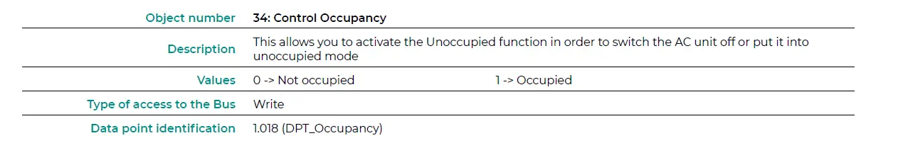
- Occupancy (internaal). Switches to Occupied mode when the configured digital input is activated.
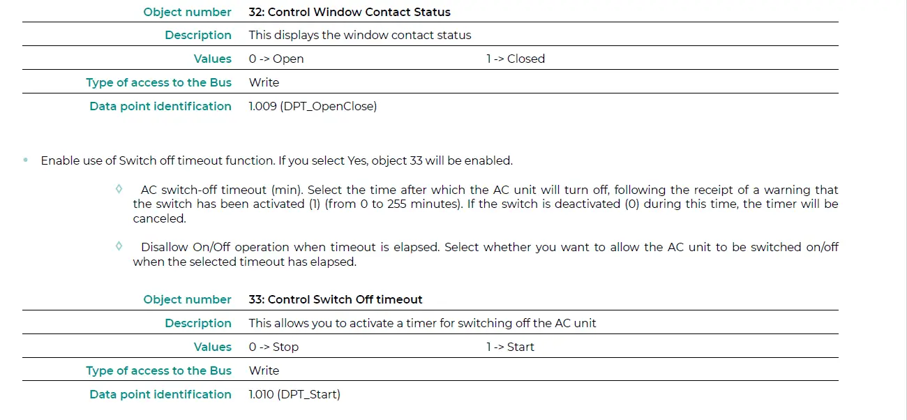
- Window (internal). Activates the Window Contact timer when this digital input is activated.
- Switching
Communication objects
Digital input status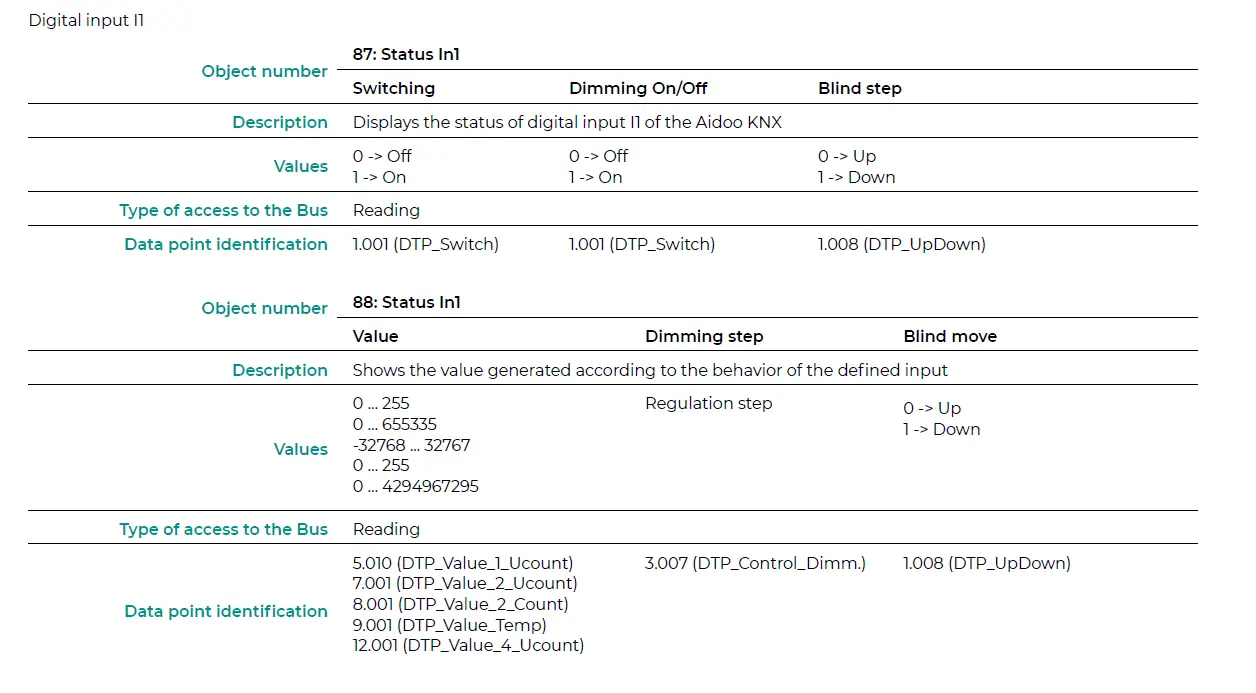
KNX parameters for LG
LGE PROTOCOL
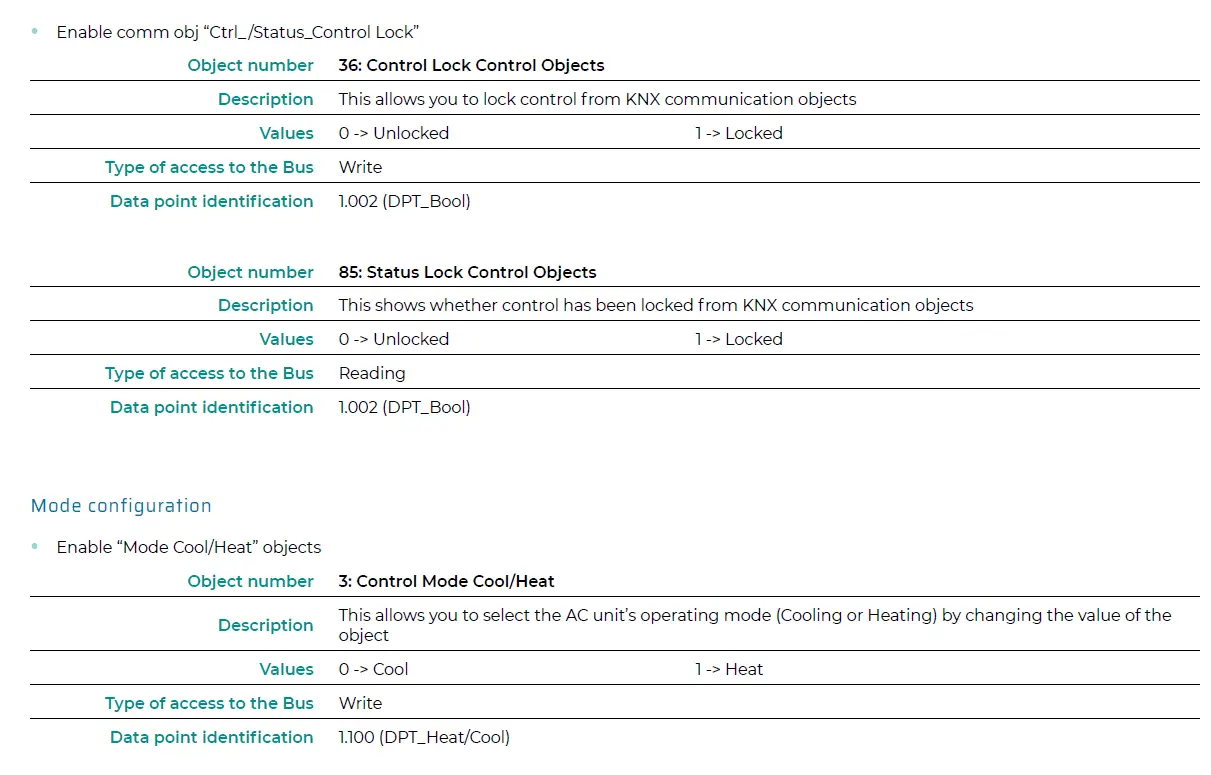
| 3 Control Mode Cool / Heat W 1 -> Heat | DPT_Heat/Cool | 1.100 | ||
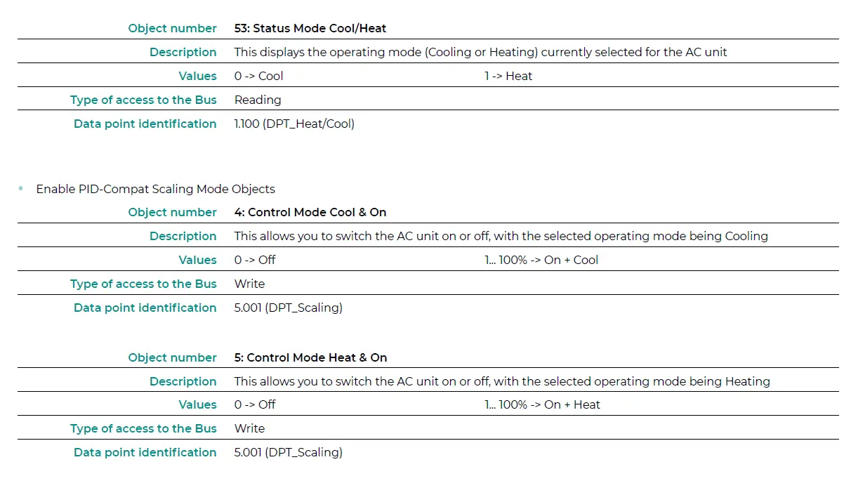
| 0% -> Off 4 Control Mode Cool & On W 0.1% – 100% -> On + Cool | DPT_Scaling | 5.001 | ||
| 0% -> Off | ||||
| 5 Control Mode Heat & On | 0.1% – 100% -> On + Heat | W | DPT_Scaling | 5.001 |
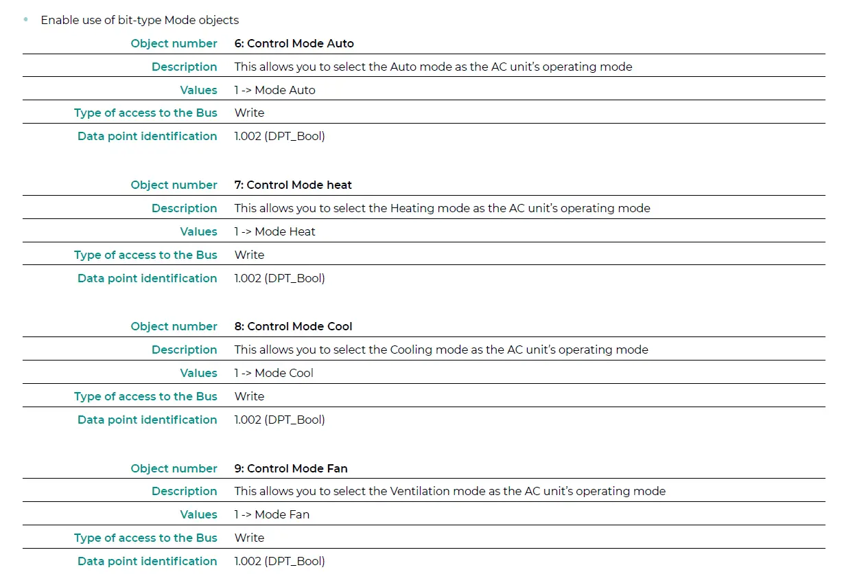
| 6 Control Mode Auto | 1 -> Auto | W | DPT_Bool | 1.002 |
| 7 Control Mode Heat | 1 -> Heat | W | DPT_Bool | 1.002 |
| 8 Control Mode Cool | 1 -> Cool | W | DPT_Bool | 1.002 |
| 9 Control Mode Fan | 1 -> Fan | W | DPT_Bool | 1.002 |
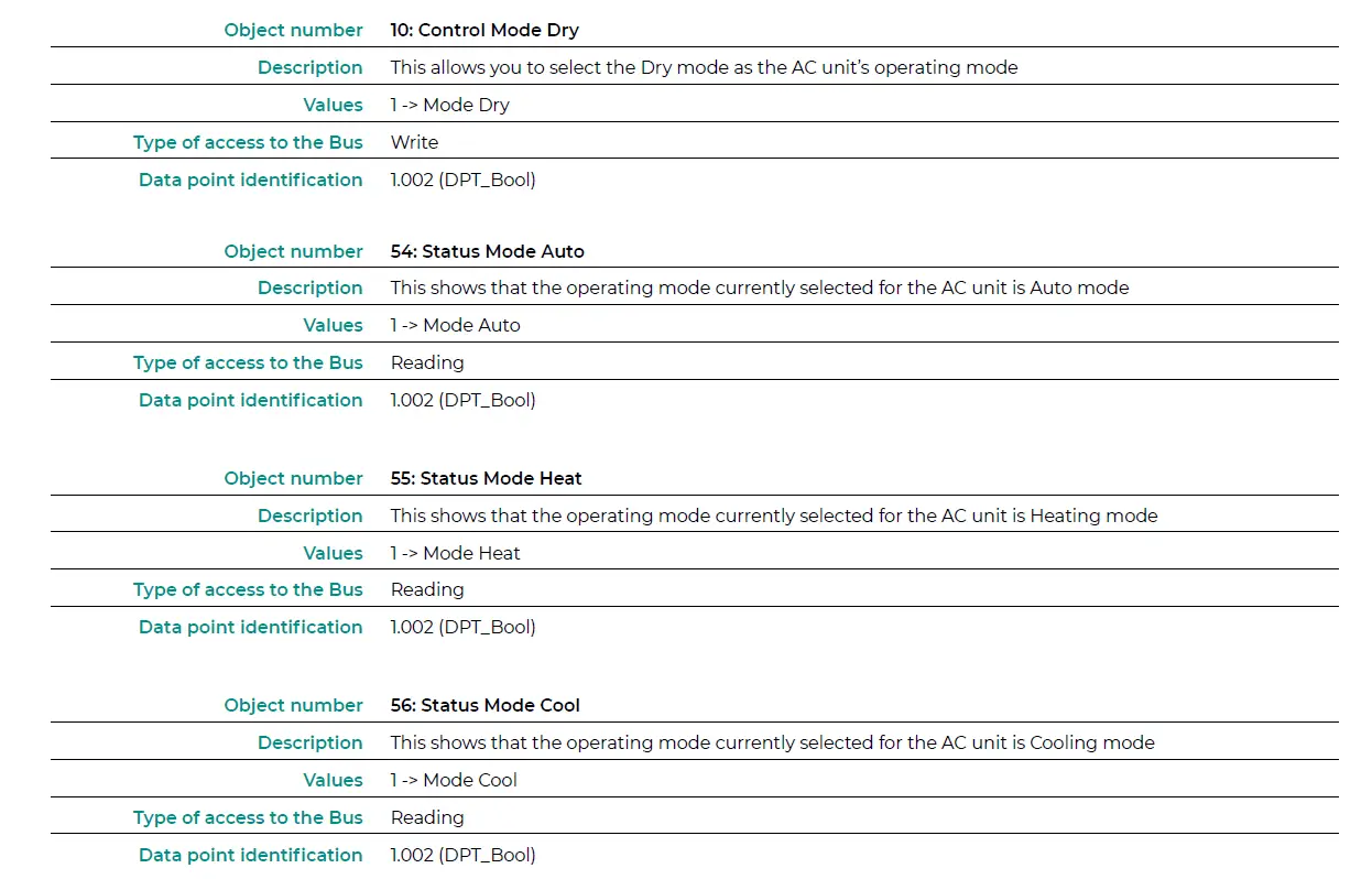
| 10 Control Mode Dry | 1 -> Dry | W | DPT_Bool | 1.002 |
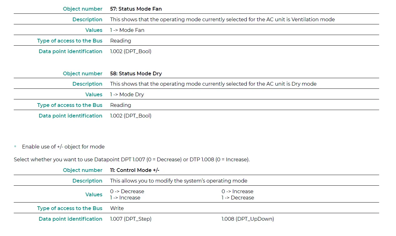
| 0 -> Decrease | ||||
| W 1 -> Increase | DPT_Step | 1.007 | ||
| 11 Control Mode + / – | 0 -> Increase W 1-> Decrease | DPT_UpDown | 1.008 | |
| 0% – 49% -> Speed 1 | ||||
| 50% – 82% -> Speed 2 W | DPT_Scaling | 5.001 | ||
| 12 Control Fan Speed / 3 Speeds | 83% – 100% -> Speed 3 1 -> Speed 1 | |||
| 2 -> Speed 2 | W | DPT_Enumerated | 5.010 | |
| 3 -> Speed 3 | ||||
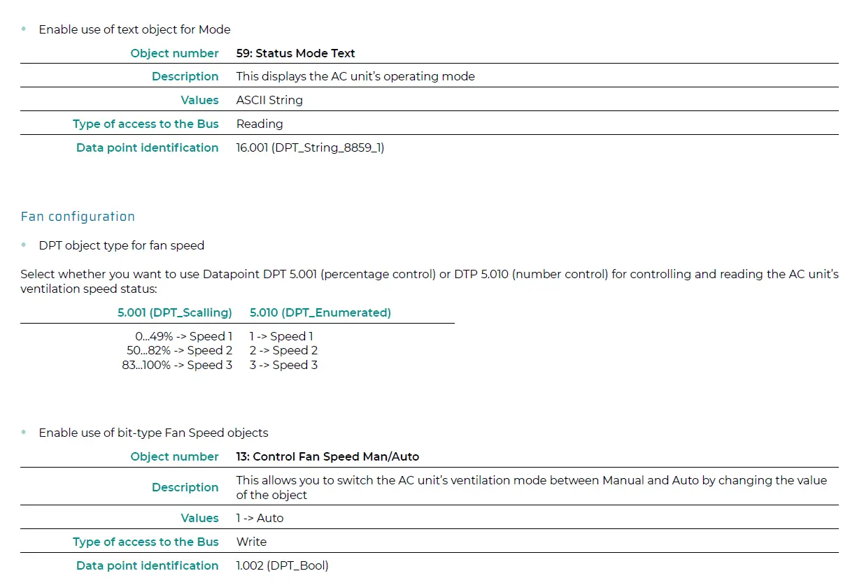
| 13 Control Fan Speed Man / Auto | 1 -> Auto | W | DPT_Bool | 1.002 |
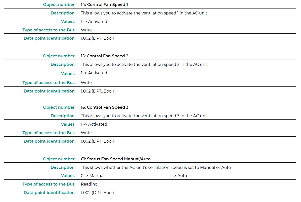
| 14 Control Fan Speed 1 | 1 -> Activated | W | DPT_Bool | 1.002 |
| 15 Control Fan Speed 2 | 1 -> Activated | W | DPT_Bool | 1.002 |
| 16 Control Fan Speed 3 | 1 -> Activated | W | DPT_Bool | 1.002 |
| 0 -> Decrease | ||||
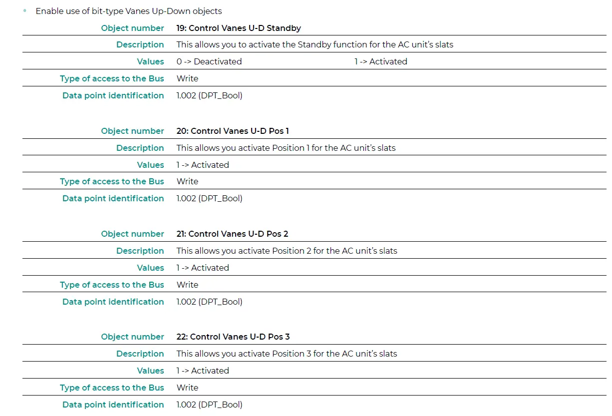
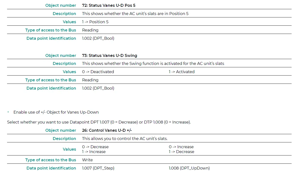
| 19 | Control Vanes U-D Standby |
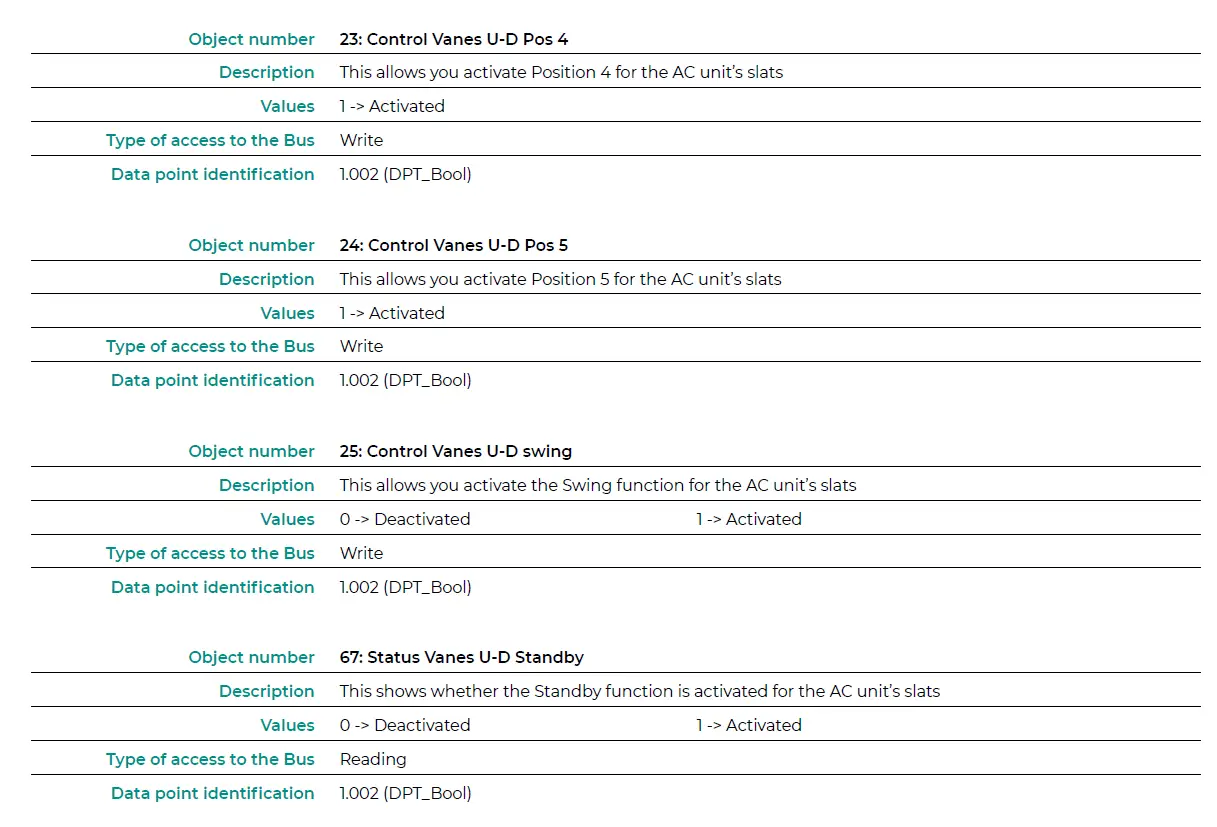
| 25 | Control Vanes U-D Swing |
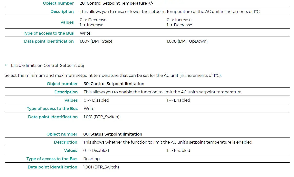
| 27 | Control Setpoint Temperature |
|
0 -> Auto | |||||
| 1 -> Heat | |||||
| 52 | Status Mode | 3 -> Cool R DPT_HVACContrMode 20.105 | |||
| 9 -> Fan | |||||
| 14 -> Dry | |||||
| 0 -> Cool | |||||
| 53 Status Mode Cool / Heat | 1 -> Heat | R | DPT_Heat/Cool | 1.100 | |
| 54 Status Mode Auto | 1 -> Auto | R | DPT_Bool | 1.002 | |
| 55 Status Mode Heat | 1 -> Heat | R | DPT_Bool | 1.002 | |
| 56 Status Mode Cool | 1 -> Cool | R | DPT_Bool | 1.002 | |
| 57 Status Mode Fan | 1 -> Fan | R | DPT_Bool | 1.002 | |
| 58 Status Mode Dry | 1 -> Dry | R | DPT_Bool | 1.002 | |
| 59 Status Mode Text | ASCII String | R | DPT_String_8859_1 | 16.001 | |
| 33% -> Speed 1 | |||||
| 67% -> Speed 2 | R | DPT_Scaling | 5.001 | ||
| 60 | 100% -> Speed 3 Status Fan Speed / 3 Speeds | ||||
| 1 -> Speed 1 2 -> Speed 2 R | DPT_Enumerated | 5.010 | |||
| 3 -> Speed 3 0 -> Manual | |||||
| 61 Status Fan Speed Manual / Auto | 1 -> Auto | R | DPT_Bool | 1.002 | |
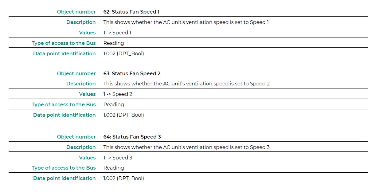
| 62 Status Fan Speed 1 | 1 -> Speed 1 | R | DPT_Bool | 1.002 | |
| 63 Status Fan Speed 2 | 1 -> Speed 2 | R | DPT_Bool | 1.002 | |
| 64 Status Fan Speed 3 | 1 -> Speed 3 | R | DPT_Bool | 1.002 | |
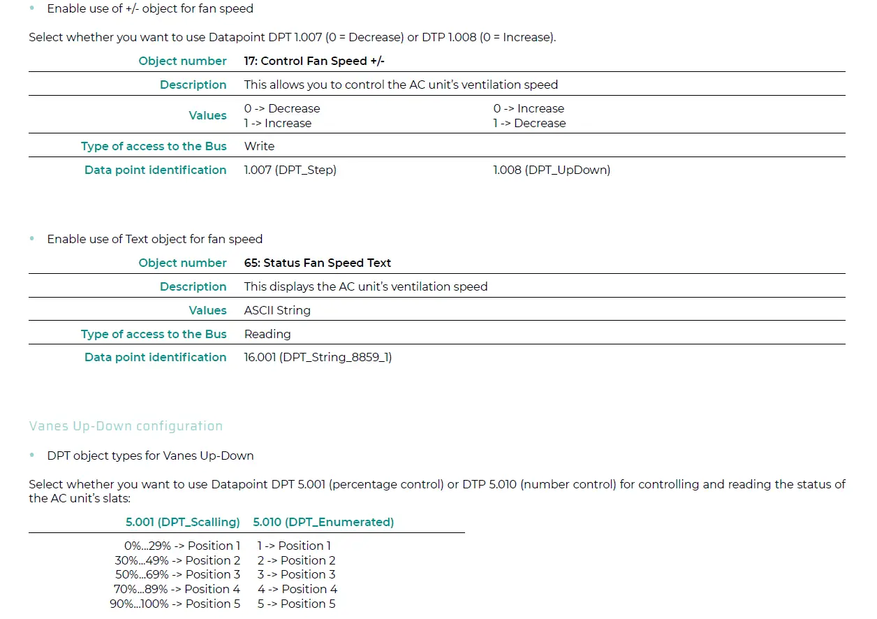
| 65 Status Fan Speed Text | ASCII String | R | DPT_String_8859_1 | 16.001 | |
| 0 -> Deactivated 73 Status Vanes U-D Swing R 1 -> Activated | DPT_Bool | 1.002 | |||
| 75 Status AC Setpoint Temperature Varies depending on manufacturer R | DPT_Value_Temp | 9.001 | |||
| 76 Status AC Return Temperature Varies depending on manufacturer R | DPT_Value_Temp | 9.001 | |||
| 77 Internal probe temperature Varies depending on manufacturer R | DPT_Value_Temp | 9.001 | |||
| 0 -> No alarm 79 Status Reset Filter R 1 -> Alarm | DPT_Bool | 1.002 | |||
| Object Name Values Flags | Datapoint | |||||
| 0 -> Disabled 80 Status Setpoint limitation R 1 -> Enabled | DPT_Switch | 1.001 | ||||
| 0 -> No error / alarm 81 Status Error / Alarm R 1 -> An error / alarm has occurred | DPT_Alarm | 1.005 | ||||
| 82 | Error text code Varies depending on manufacturer R | DPT_String_8859_1 | 16.001 | |||
| 0 -> Off Status In1 – Switching R 1 -> On | DPT_Switch | 1.001 | ||||
| 87 | 0 -> Off Status In1 – Dimming On / Off R 1 -> On | DPT_Switch | 1.001 | |||
| 0 -> Up | ||||||
| Status In1 – Blind Step | 1 -> Down | R | DPT_UpDown | 1.008 | ||
| Status In1 – Value | 1 byte unsigned | R | DPT_Value_1_Ucount | 5.010 | ||
| Status In1 – Value | 2 byte unsigned | R | DPT_Value_2_Ucount | 7.001 | ||
| Status In1 – Value | 2 byte signed | R | DPT_Value_2_Count | 8.001 | ||
| Status In1 – Value | Temperature (ºC) | R | DPT_Value_Temp | 9.001 | ||
| 88 | Status In1 – Value | 4 byte unsigned | R | DPT_Value_4_Ucount | 12.001 | |
| Status In1 – Dimming Step | Dimming step | R | DPT_Control_Dimm. | 3.007 | ||
| 0 -> Up Status In1 – Blind Move R 1 -> Down | DPT_UpDown | 1.008 | ||||
| 0 -> Off Status In2 – Switching R 1 -> On | DPT_Switch | 1.001 | ||||
| 89 | 0 -> Off Status In2 – Dimming On / Off R 1 -> On | DPT_Switch | 1.001 | |||
| 0 -> Up | ||||||
| Status In2 – Blind Step | 1 -> Down | R | DPT_UpDown | 1.008 | ||
| Status In2 – Value | 1 byte unsigned | R | DPT_Value_1_Ucount | 5.010 | ||
| Status In2 – Value | 2 byte unsigned | R | DPT_Value_2_Ucount | 7.001 | ||
| Status In2 – Value | 2 byte signed | R | DPT_Value_2_Count | 8.001 | ||
| Status In2 – Value | Temperature (ºC) | R | DPT_Value_Temp | 9.001 | ||
| 90 | Status In2 – Value | 4 byte unsigned | R | DPT_Value_4_Ucount | 12.001 | |
| Status In2 – Dimming Step | Dimming step | R | DPT_Control_Dimm. | 3.007 | ||
| 0 -> Up Status In2 – Blind Move R 1 -> Down | DPT_UpDown | 1.008 | ||||
| 0 -> Off Status In3 – Switching R 1 -> On | DPT_Switch | 1.001 | ||||
| 91 | 0 -> Off Status In3 – Dimming On / Off R 1 -> On | DPT_Switch | 1.001 | |||
| 0 -> Up | ||||||
| Status In3 – Blind Step | 1 -> Down | R | DPT_UpDown | 1.008 | ||
| Status In3 – Value | 1 byte unsigned | R | DPT_Value_1_Ucount | 5.010 | ||
| Status In3 – Value | 2 byte unsigned | R | DPT_Value_2_Ucount | 7.001 | ||
| Status In3 – Value | 2 byte signed | R | DPT_Value_2_Count | 8.001 | ||
| Status In3 – Value | Temperature (ºC) | R | DPT_Value_Temp | 9.001 | ||
| 92 | Status In3 – Value | 4 byte unsigned | R | DPT_Value_4_Ucount | 12.001 | |
| Status In3 – Dimming Step | Dimming step | R | DPT_Control_Dimm. | 3.007 | ||
| 0 -> Up Status In3 – Blind Move R | DPT_UpDown | 1.008 | ||||
| 1 -> Down | ||||||


