mXion RD6 6-Channel Relay Decoder User Manual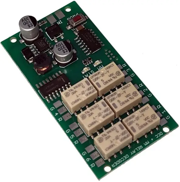
Introduction
Dear customer, we strongly recommend that you read these manuals and the warning notes thoroughly before installing and operating your device. The device is not a toy (15+).
NOTE: Make sure that the outputs are set to appropriate value before hooking up any other device. We can’t be responsible For any damage if this is disregarded.
General information
We recommend studying this manual thoroughly before installing and operating your new device. Place the decoder in a protected location. The unit must not be exposed to moisture.
NOTE: Some functions are only available with the latest firmware. Please make sure that your device is programmed with the latest firmware.
Summary of Functions
- DCC NMRA digital operation
- Compatible NMRA-DCC module
- Marklin-Motorola digital operation
- Very small outlet
- 6 relay function output (doubled)
- 18 effect for each output activable
- Outputs invertable
- Reset function for all CV values
- Ideally for station lamps and more:
- Ideally for high loads and galvanic
- Very low power consumption
- Ideally for heart polarisation
- Ideally for disconnect tracks
- Ideal! for switching AC power
- Save last switch position
- Easy function mapping
- Adresses independetly
- Switchable with loco and switch addresses
- Programming via programming switch
- Multiple programming options
- (Bitwise, CV, POM accessoire decoder, register)
- Needs no programming load
Scope of supply
- Manual
- mXion RD6
Hook-Up
Install your device in compliance with the connecting diagrams in this manual. The device is protected against shorts and excessive loads. However, in case of a connection error e.g. a short this safety feature can’t work and the device will be destroyed subsequently. Make sure that there is no short circuit caused by the mounting screws or metal.
NOTE: Please note the CV basic settings in the delivery state.
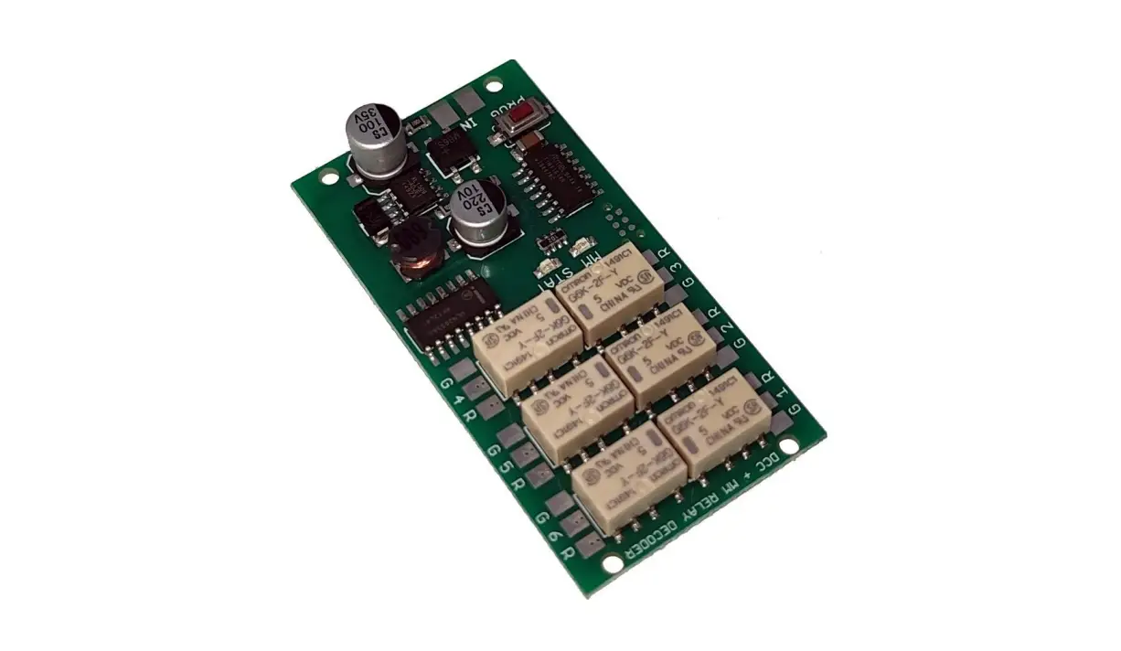
Connectors
Terminal „number” + R is connected when switched off state (NC). „Number” + G is open in the off state (NO).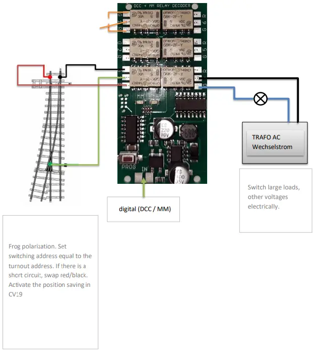
Product description
The mXion RD6 is a very small but powerful 6 ch. relay decoder for universal. Thanks to the independent up to 1 Amps load per relay outputs with double relays, the decoder is univaersal usable. This allows large loads to be carried out for one normal decoders are too big (e.g. evaporators, locomotive plug) can be switched das well as for the using frog polarization, switchable siding, garden lighting or much more where galvanic isolation is required.
He offers various programmable functions like flashing, pairwise flashing and over 16 other effects (18 in total). This includes simulations such as TV, Neon, Petroleum, Welding, US lights and much more. The effects are great for street lamps, even entire streets, houses and much more.
The 6 turnout addresses can be independently program and do not need each other be following. In addition to the usual CV programming also supports the module a programming switch to quickly get the addresses to be able to change.
The module supports DCC and Motorola, so this decoder can be used universally.
Programming lock
To prevent accidental programming to prevent CV 15/16 one programming lock. Only if CV 15 = CV 16 is a programming possible. Changing CV 16 changes automatically also CV 15. With CV 7 = 16 can the programming lock reset.
STANDARD VALUE CV 15/16 = 75
Programming options
This decoder supports the following programming types: bitwise, POM and CV read & write and register-mode and programming switch.
There will be no extra load for programming.
In POM (programming on main track) the programming lock is also supported. The decoder can also be on the main track programmed without the other decoder to be influenced. Thus, when programming the decoder can not be removed.
NOTE: To use POM without others decoder must affect your digital center POM to specific decoder adresses (e.g. Mascot° control panels)
Programming binary values
Some CV’s (e.g. 29) consist of so-called binary values. The means that several settings in a value. Each function has a bit position and a value. For programming such a CV must have all the significances can be added. A disabled function has always the value O.
EXAMPLE: You want 28 drive steps and long low address. To do this, you must set the value in CV 29 2 + 32 = 34 programmed.
Programming switch address
Switch addresses consist of 2 values. For addresses < 256 the value can be directly in address low. The high address is 0. If the address is > 255 this is as follows (for example address 2000):
2000 / 256 = 7,81, address high is 7 2000 — (7 x 256) = 208, address low is then 208.
About the programming button:
Clock on the switch button during operation, the STATUS LED will alternate in 1 sec. clocking.
Switch on the desired control unit on the control unit switch address, then the LED will be cleared. In order to the address has been accepted correctly and all 6 outputs are numbered.
If the button will pressed again without sending a command, the operation will be canceled.
Reset functions
The decoder can be reset via CV 7. Various areas can be used for this purpose. Write with the following values:
- 11 (basic functions) 1
- 6 (programming lock CV 15/16)
- 33 (switch outputs)
CV-Table
S = Default, L = Loco address, S = Switch address, LS = Loco and switch address usable
| CV | Description | S | L/S | Range | Note |
| 1 | Lokadresse | 3 | L | 1 – 127 | only if CV14 = 0 |
| 7 | Software version | – | – | read only (10 = 1.0) | |
| 7 | Decoder reset functions | ||||
| 3 ranges available | 11 16 33 | basic settings (CV 1,11-13,17-19) programming lock (CV 15/16) function- & Switch outputs (CV 20-49) | |||
| 8 | Manufacturer ID | 160 | – | read only | |
| 7+8 | Register programming mode | ||||
| Reg8 = CV-Address Reg7 = CV-Value | CV 7/8 don’t changes his real value CV 8 write first with cv-number, then CV 7 write with value or read (e.g.: CV 49 should have 3) è CV 8 = 49, CV 7 = 3 writing | ||||
| 9 | SDF-House time min in minute | 3 | S | 1 – 255 | minimal time for reload rate |
| 10 | SDF- House time max in minute | 15 | S | 1 – 255 | maximum time for reload rate |
| 12 | Random generator | 0 | W | 0 – 255 | Add value to the CV for function 0 = reactive +1 = A1, +2 = A2, +4 = A3, +8 = A4, +16 = A5, +32 = A6 |
| 13 | Automatic protocoll detection | 0 | LS | 0/1 | 0 = automatic detection 1 = only DCC (recommended for multi- protocol command stations) |
| 14 | Locomotive/switch control | 1 | LS | 0/1 | 0 = locomotive control 1 = turnout control |
| 15 | Programming lock (key) | 75 | S | 0 – 255 | to lock only change this value |
| 16 | Programming lock (lock) | 75 | S | 0 – 255 | changes in CV 16 will change CV 15 |
| 17 | SDF time for function | 10 | S | 0 – 255 | time base (10 ms / value) |
| 18 | Switch address calculation | 0 | S | 0/1 | 0 = Switch address like norm 1 = Switch address like Rocco, Fleischmann |
| 19 | Restore last position after restart or voltage drop | 0 | LS | 0 – 255 | Add value to the CV for function 0 = dative +1 = A1, +2 = A2, +4 = A3, +8 = A4, +16 = A5, +32 = A6 |
S = Default, L = Loco address, S = Switch address, LS = Loco and switch address usable
| 20 | A1 switch address high | 0 | S | 1 – 2048 | switch output 1, if address smaller 256 easy program CV21 = desired address! |
| 21 | A1 switch address low | 1 | S | ||
| 22 | A1 function key for loco command (F0 – F68) | 1 | L | 0 – 68 | only active, if cv14 = 0. Control over CV1 loco address and f-keys |
| 23 | A1 special function | 0 | S | see attachment 1 | |
| 24 | A1 time for special function | 5 | S | 1 – 255 | time base (0,1s / value) |
| 25 | A2 switch address high | 0 | S | 1 – 2048 | switch output 2, if address smaller 256 easy program CV26 = desired address! |
| 26 | A2 switch address low | 2 | S | ||
| 27 | A2 function key for loco command (F0 – F68) | 2 | L | 0 – 68 | only active, if cv14 = 0. Control over CV1 loco address and f-keys |
| 28 | A2 special function | 0 | LS | see attachment 1 | |
| 29 | A2 time for special function | 5 | LS | 1 – 255 | time base (0,1s / value) |
| 30 | A3 switch address high | 0 | S | 1 – 2048 | switch output 3, if address smaller 256 easy program CV31 = desired address! |
| 31 | A3 switch address low | 3 | S | ||
| 32 | A3 function key for loco command (F0 – F68) | 3 | S | 0 – 68 | only active, if cv14 = 0. Control over CV1 loco address and f-keys |
| 33 | A3 special function | 0 | LS | see attachment 1 | |
| 34 | A3 time for special function | 5 | LS | 1 – 255 | time base (0,1s / value) |
| 35 | A4 switch address high | 0 | S | 1 – 2048 | switch output 4, if address smaller 256 easy program CV36 = desired address! |
| 36 | A4 switch address low | 1 | S | ||
| 37 | A4 function key for loco command (F0 – F68) | 4 | L | 0 – 68 | only active, if cv14 = 0. Control over CV1 loco address and f-keys |
| 38 | A4 special function | 0 | LS | see attachment 1 | |
| 39 | A4 time for special function | 5 | LS | 1 – 255 | time base (0,1s / value) |
| 40 | A5 switch address high | 0 | S | 1 – 2048 | switch output 5, if address smaller 256 easy program CV41 = desired address! |
| 41 | A5 switch address low | 2 | S | ||
| 42 | A5 function key for loco command (F0 – F68) | 5 | L | 0 – 68 | only active, if cv14 = 0. Control over CV1 loco address and f-keys |
| 43 | A5 special function | 0 | LS | see attachment 1 | |
| 44 | A5 time for special function | 5 | LS | 1 – 255 | time base (0,1s / value) |
| 45 | A6 switch address high | 0 | S | 1 – 2048 | switch output 6, if address smaller 256 easy program CV46 = desired address! |
| 46 | A6 switch address low | 3 | S | ||
| 47 | A6 function key for loco command (F0 – F68) | 6 | L | 0 – 68 | only active, if cv14 = 0. Control over CV1 loco address and f-keys |
| 48 | A6 special function | 0 | LS | see attachment 1 | |
| 49 | A6 time for special function | 5 | LS | 1 – 255 | time base (0,1s / value) |
| ATTACHMENT 1 – Special function | ||
| Value | Application | Note |
| 0 | no special function (normal output) | |
| 1 | flash symmetric | time base (0,1s / value) |
| 2 | flash asymmetric short ON (1:4) | time base (0,1s / Value) is for the long value |
| 3 | flash a symmetric long ON (4:1) | |
| 4 | Photographer flash | time base (0,25s / value) |
| 5 | mono flop (automatic switch off) | time base (0,1s / value) |
| 6 | switch on delayed | time base (0,1s / value) |
| 7 | firebox | |
| 8 | TV flickering | |
| 9 | petroleum flickering | |
| 10 | fluorescent tube | |
| 11 | defective fluorescent tube | |
| 12 | alternating flash to paired output | in combination with second output (e.g. A1 & A2, A3 & A4) |
| 13 | US strobe light | |
| 14 | US double strobe light | |
| 15 | US mars light | time base (0,1s / value) |
| 16 | US ditch light | in combination with second output (e.g. A1 & A2, A3 & A4), 1st output normal light, 2nd ditch light function |
| 17 | sodium lamp | |
| 18 | welding light | use with blue led |
| +32 | add switch off delayed | add value to function |
| +64 | add switch on delayed | add value to function |
| +128 | invers | add value to function |
Technical data
- Power supply: 7.27V DC/DCC 5-18V AC
- Current: 5mA (with out functions)
- Maximum function current: each Relays 1Amps.
- Maximum current: 0.08 Amps.
- Temperature range: -40 up to 85°C
- Dimensions L*B*H (cm): 6113*1.5
- NOTE: In case you intend to utilize this device below freezing temperatures, make sure it was stored in a heated environment before operation to prevent the generation of condensed water. During operation is sufficient to prevent condensed water.
Warranty, Service, Support
micron dynamics warrants this product against defects in materials and workmanship for one year from the original date of purchase. Other countries might have different legal warranty situations. Normal wear and tear, consumer modifications as well as improper use or installation are not covered. Peripheral component damage is not covered by this warranty. Valid warrants claims will be serviced without charge within the warranty period. For warranty service please return the product to the manufacturer. Return shipping charges are not covered by micron-dynamics. Please include your proof of purchase with the returned good. Please check our website for up to date brochures, product information, documentation and software updates. Software updates you can do with our updater or you can send us the product, we update for you free.
Errors and changes excepted.
Hotline
For technical support and schematics for application examples contact:
micron-dynamics
[email protected]
[email protected]
www.micron-dynamics.de
https://www.youtube.com/@micron-dynamics