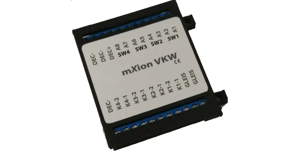
mXion VKW Switch Decoder
![]()
Introduction
Dear customer, we strongly recommend that you read these manuals and the warning notes thouroughly before installing and operating your device. The device is not a toy (15+).
NOTE: Make sure that the outputs are set to appropriate value before hooking up any other device. We can’t be responsible For any damage if this is disregarded.
General information
We recommend studying this manual thoroughly before installing and operating your new device.
Place the decoder in a protected location. The unit must not be exposed to moisture.
NOTE: Some funktions are only available with the latest firmware. Please make sure that your device is programmed with the latest firmware.
Summary of Functions
DCC NMRA digital operation
Engine, switch decoder
Compatible NMRA-DCC module 8 contact inputs for many functions as (switch on, off, pairwise, direction depending and more) for Manuel controlling 8 reinforced function outputs in loco op.
- Programmable functions in loco operation 4
- Switch outputs (2- and 3 wire & engine)
- Massive connectors, also for contact inputs
- All contacts on roof are numerated
- Intelligent switching for 3-Way switches
- Implemented function for decouple tracks
- Defined start switching position
- Automatic switch back functions
- Outputs invertible
- Controllable by loco or switch addresses
- Function and switch outputs dimmable
- Turnout roads with 1 command
- Up to 3 points routes can be stored
- Turnouts without control of the central unit
- Reset function for all CV values
- Easy function mapping
- 28 function keys programmable, 10239 loco addresses, 2048 switch addresses 14, 28, 128 speed steps (automatically)
- Multiple programming options (Bitwise, CV, POM accesso ire decoder, register)
- Needs no programming load
Scope of supply
- Manual
- mXion PWD
Hook-Up
Install your device in compliance with the connecting diagrams in this manual. The device is protected against shorts and excessive loads. However, in case of a connection error e.g. a short this safety feature can’t work and the device will be destroyed subsequently. Make sure that there is no short circuit caused by the mounting screws or metal.
NOTE: Please note the CV basic settings in the delivery state.
Connectors
Switch loads between A1-A8 and common + pole.
Use with 3-wire switches the common + pole as the center line.
Not use 3 pole LGB drives!
Also in switch mode (CV29 Bit 7 = 1) it’s possible to use DEC+ as common pole for lanterns e.g.
Not use 3 pole LGB drives!
Up to 4 switches and up to 8 consumers as lamps or engines are controllable!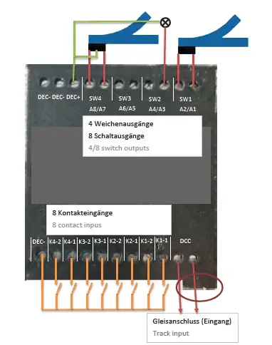
Product description
The mXion VKW is a strong 4 channel switch decoder he can optional work in loco mode with 8 function outputs.
The four points are also independently of one another and freely addressable.
For this purpose, dimming and time units.
Here are the special features as with the mXion AKW that one integrated 3-way switch is implemented. This controls
3-way switches so that always has a defined direction of the soft takes place and derailments can be eliminated. Fit the switch to „straight“ if using this mode or use CV 49 Bit 2/3 = 1.
The rear tongue automatically switches on „straight“ when the front is operated.
Switches one the front tongue back again, so also takes the rear tongue again the old direction. If the front tongue is on „branch“ and the rear tongue is now switched and the anterior tongue in the appropriate direction, so that on the one hand there are no derailments of vehicles and on the other hand the operation of the 3-way switch is simplified. So you can use the address for the switch the front tab „branch right“ and with the address for the rear tongue „straight“ or „branch left“. The other tongue
will automatically so that does not must happen.
Another highlight of the VWK is the setting for decoupling tracks. Here you can create a corresponding function output (A7 to SW1 and A8 to SW2 bound in this mode) CV 49 Bit 0 and automatically with of the switch.
The advantage ist hat the luminous “E” of the LGB® decoupling track as the decouple is active. Now, weather the decouple is still disengaged or coupling.
Ideally, the two modes, complement each other with the mode for defined position. The outputs of the switches switch
automatically to „stop“ or „branch“.
This hast he advantage that signals on red, decoupling tracks to normal and turn switches to „branch“ after the system has been switched on.
So you always have a defined starting position.
TIPP: Use the global switch address in CV200/201 to select all route addresses (SW1-SW4) automatically sequentially. Write the address for SW1 in CV200/201 write CV201 (address byte high) first then CV200 address byte low. According to describe of CV200, SW1-SW4 will be consecutive where SW1 is the address of CV200 and CV201 and SW4 accordingly the address of SW1 + 4.
Contact inputs
The decoder offers the option of the switch outputs via contacts (manual) to be able to switch. The contact inputs are protected against positive voltages and switch to ground (DEC-).
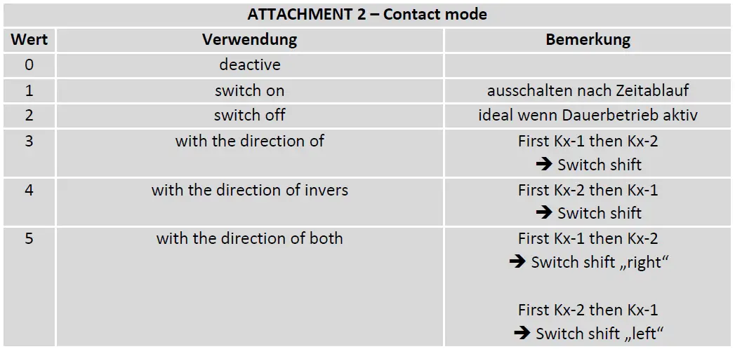
With the contact inputs it is possible div. How to do switching tasks e.g. switching a turnout via track contacts. For example turnouts can be used switched or even direction-dependent be switched that inverse as well with double direction. That means that one train with a solenoid first K1 afterwards K2 of the output is actuated and the switch switches in a corresponding direction. The direction is invertible via CV 117.
Also, the contact inputs provide the possibility this as a limit switch to turn off a feature to use.
Continue to work with the contacts all turnout settings such as the inversion of individual outlets (switching right/left) etc.
Turnout-Routes
The decoder supports the usual turnpike from the central unit or handset to be sent.
As a one-off extra, the decoder supports manual switch routes. That is one can use 2 CVs a separate – independent set addr. for a route.
About another CV can be specified which of the existing points exits to be used for the road. A 4th and last CV gives the switch direction in the process. In total 3 of these assigned to manual routes. The CVs are from CV30 and upper.
Now you can by a separate – from the switch outputs independent address trigger the command that the decoder the before set route switches.
This system is important for control units that do not handle any routes and just with one click a road to go!
Programming lock
To prevent accidental programming to prevent CV 15/16 one programming lock. Only if CV 15 = CV 16 is a programming possible. Changing CV 16 changes automatically also CV 15.
With CV 7 = 16 can the programming lock reset.
STANDARD VALUE CV 15/16 = 140
Programming options
This decoder supports the following programming types: bitwise, POM and CV read & write and register-mode.
There will be no extra load for programming.
In POM (programming on main track) the programming lock is also supported. The decoder can also be on the main track programmed without the other decoder to be influenced. Thus, when programming the decoder can not be removed.
NOTE: To use POM without others decoder must affect your digital center POM to specific decoder addresses
Programming binary values Some CV’s (e.g. 29) consist of so-called binary values. The means that several settings in a value. Each function has a bit position and a value.
For programming such a CV must have all the significances can be added. A disabled function has always the value 0.
EXAMPLE: You want 28 drive steps and long loco address. To do this, you must set the value in CV 29 2 + 32 = 34 programmed.
Programming switch address
Switch addresses consist of 2 values.
For addresses < 256 the value can be directly in address low. The high address is 0. If the address is > 255 this is as
follows (for example address 2000):
- 2000 / 256 = 7,81, address high is 7
- 2000 – (7 x 256) = 208, address low is then 208.
- Program these values into the SW1-SW4 CVs.
Programming loco adress
Locomotives up to 127 are programmed directly to CV 1. For this, you need CV 29
Bit 5 „off“ (will set automaticly).
If larger addresses are used, CV 29 – Bit 5 must be „on“ (automatically if change CV 17/18). The address is now in CV 17
and CV 18 stored. The address is then like follows (e.g. loco address 3000):
3000 / 256 = 11,72; CV 17 is 192 + 11 = 203. 3000 – (11 x 256) = 189; CV 18 is then 189.
Reset functions
The decoder can be reset via CV 7. Various areas can be used for this purpose.
Write with the following values:
- 11 (basic functions)
- 16 (programming lock CV 15/16)
- 22 (function outputs)
- 33 (switch outputs)
Function output features
| Funktion | SW1 (A1/A2) | SW2 (A3/A4) | SW3 (A5/A6) | SW4 (A7/A8) | Timevalue |
| On/Off | (X/X) | (X/X) | (X/X) | (X/X) | |
| Deactivated | (X/X) | (X/X) | (X/X) | (X/X) | |
| Permanent-On | (X/X) | (X/X) | (X/X) | (X/X) | |
| Forwards only | |||||
| Backwards only | |||||
| Standing only | |||||
| Driving only | |||||
| Timer sym. flash | X | ||||
| Timer asym. short | X | ||||
| Timer asym. long | X | ||||
| Monoflop | X | ||||
| Switch on delay | X | ||||
| Firebox | |||||
| TV flickering | |||||
| Photographer flash | X | ||||
| Petroleum flickering | |||||
| Fluorescent tube | |||||
| Pairwise alternating | X | ||||
| Atom. switch back | X | X | X | X | X |
| Dimmable | X | X | X | X |
CV-Table
S = Default, L = Loco address, S = Switch address, LS = Loco and switch address usable
| CV | Description | S | L/S | Range | Note | ||
| 1 | Loco address | 3 | L | 1 – 127 | if CV 29 Bit 5 = 0 (automatically reset) | ||
| 7 | Software version | – | – | read only (10 = 1.0) | |||
| 7 | Decoder reset functions | ||||||
| 4 ranges available | 11 16 22 33 | basic settings (CV 1,11-13,17-19,29-119) programming lock (CV 15/16) function outputs (CV 160-191) switch outputs (CV 120-159) | |||||
| 8 | Manufacturer ID | 160 | – | read only | |||
| 7+8 | Register programming mode | ||||||
| Reg8 = CV-Address Reg7 = CV-Value | CV 7/8 don’t changes his real value CV 8 write first with cv-number, then CV 7 write with value or read (e.g.: CV 49 should have 3) è CV 8 = 49, CV 7 = 3 writing | ||||||
| 15 | Programming lock (key) | 210 | LS | 0 – 255 | to lock only change this value | ||
| 16 | Programming lock (lock) | 210 | LS | 0 – 255 | changes in CV 16 will change CV 15 | ||
| 17 | Long loco address (high) | 128 | L | 128 – 10239 | actives only if CV 29 Bit 5 = 1 (automatically set if change CV 17/18) | ||
| 18 | Long loco address (low) | ||||||
| 29 | NMRA configuration | 130 | LS | bitwise programming | |||
| Bit | Value | OFF (Value 0) | ON | ||||
| 1 | 2 | 14 speed steps | 28/128 speed steps | ||||
| 5 | 32 | short loco address (CV 1) | long loco address (CV 17/18) | ||||
| 7 | 128 | loco address (A1-A16 active) | switch address (SW1-SW8) | ||||
S = Default, L = Loco address, S = Switch address, LS = Loco and switch address usable
| CV | Description | S | L/S | Range | Note |
| 30 | Route 1 high address | 0 | W | 1 – 2048 | if address smaller 256 easy program desired address to the “low” Address-CV! |
| 31 | Route 1 low address | 0 | W | ||
| 32 | Route 1 Weicheng-Reg. | 0 | W | 0 – 255 | add the value to add the switch to the route SW1 = +1, SW2 = +2, SW3 = +4, SW4 = +8, SW5 = +16, SW6 = +32, SW7 = +64, SW8 = +128 |
| 33 | Route 1 Weicheng- DIR. | 0 | W | 0 – 255 | add the value to invert the switch direction in route mode SW1 = +1, SW2 = +2, SW3 = +4, SW4 = +8, SW5 = +16, SW6 = +32, SW7 = +64, SW8 = +128 |
| 35 | Route 2 high address | 0 | W | 1 – 2048 | if address smaller 256 easy program desired address to the “low” Address-CV! |
| 36 | Route 2 low address | 0 | W | ||
| 37 | Route 2 Weicheng-Reg. | 0 | W | 0 – 255 | add the value to add the switch to the route SW1 = +1, SW2 = +2, SW3 = +4, SW4 = +8, SW5 = +16, SW6 = +32, SW7 = +64, SW8 = +128 |
| 38 | Route 2 Weicheng- DIR. | 0 | W | 0 – 255 | add the value to invert the switch direction in route mode SW1 = +1, SW2 = +2, SW3 = +4, SW4 = +8, SW5 = +16, SW6 = +32, SW7 = +64, SW8 = +128 |
| 40 | Route 3 high address | 0 | W | 1 – 2048 | if address smaller 256 easy program desired address to the “low” Address-CV! |
| 41 | Route 3 low address | 0 | W | ||
| 42 | Route 3 Weicheng-Reg. | 0 | W | 0 – 255 | add the value to add the switch to the route SW1 = +1, SW2 = +2, SW3 = +4, SW4 = +8, SW5 = +16, SW6 = +32, SW7 = +64, SW8 = +128 |
| 43 | Route 3 Weicheng-DIR. | 0 | W | 0 – 255 | add the value to invert the switch direction in route mode SW1 = +1, SW2 = +2, SW3 = +4, SW4 = +8, SW5 = +16, SW6 = +32, SW7 = +64, SW8 = +128 |
| 48 | Switch address calculation | 0 | S | 0/1 | 0 = Switch address like norm 1 = Switch address like Rocco, Fleischmann |
S = Default, L = Loco address, S = Switch address, LS = Loco and switch address usable
| CV | Description | S | L/S | Range | Note | ||
| 49 | mXion configuration | 0 | S | bitwise programming | |||
| Bit | Value | OFF (Value 0) | ON | ||||
| 0 | 1 | SW4 normal function | SW4 for 2 decoupler lamps | ||||
| 1 | 2 | SW1/SW2 normal function | SW1/SW2 3-way-switch active | ||||
| 2 | 4 | SW3/SW4 normal function | SW3/SW4 3-way-switch active | ||||
| 107 | K1-1 mode | 1 | W | 0 – 5 | siehe attachment 2 | ||
| 108 | K1-2 mode | 1 | W | 0 – 5 | siehe attachment 2 | ||
| 109 | K2-1 mode | 1 | W | 0 – 5 | siehe attachment 2 | ||
| 110 | K2-2 mode | 1 | W | 0 – 5 | siehe attachment 2 | ||
| 111 | K3-1 mode | 1 | W | 0 – 5 | siehe attachment 2 | ||
| 112 | K3-2 mode | 1 | W | 0 – 5 | siehe attachment 2 | ||
| 113 | K4-1 mode | 1 | W | 0 – 5 | siehe attachment 2 | ||
| 114 | K4-2 mode | 1 | W | 0 – 5 | siehe attachment 2 | ||
| 116 | Switch start position | 0 | S | 0 – 255 | add the values to the active the function! SW1 = +1, SW2 = +2, SW3 = +4, SW4 = +8 | ||
| 117 | start position invers | 0 | S | 0 – 255 | add the values to invert start position! SW1 = +1, SW2 = +2, SW3 = +4, SW4 = +8 | ||
| 118 | Switch output invers | 0 | S | 0 – 255 | add the values to the desired function! SW1 = +1, SW2 = +2, SW3 = +4, SW4 = +8 | ||
| 120 | SW1 address high | 0 | S | 1 – 2048 | switch output 1, if address smaller 256 easy programm CV121 = desired address! | ||
| 121 | SW1 address low | 1 | S | ||||
| 122 | SW1 dimming value | 100 | S | 1 – 100 | dimming value in % (1 % approx. 0,2 V) | ||
| 123 | SW1 time for automatic switch back function | 0 | S | 0 – 255 | 0 = off 1 – 255 = time base 0,25 sec. each value | ||
| 124 | SW1 switch off time | 5 | S | 0 – 255 | 0 = permanent on 1 – 255 = time base 0,25 sec. each value | ||
| 125 | SW2 address high | 0 | S | 1 – 2048 | switch output 2, if address smaller 256 easy programm CV126 = desired address! | ||
| 126 | SW2 address low | 2 | S | ||||
| 127 | SW2 dimming value | 100 | S | 1 – 100 | dimming value in % (1 % approx. 0,2 V) | ||
| 128 | SW2 time for automatic switch back function | 0 | S | 0 – 255 | 0 = off 1 – 255 = time base 0,25 sec. each value | ||
| 129 | SW2 switch off time | 5 | S | 0 – 255 | 0 = permanent on 1 – 255 = time base 0,25 sec. each value | ||
| 130 | SW3 address high | 0 | S | 1 – 2048 | switch output 3, if address smaller 256 easy programm CV131 = desired address! |
| 131 | SW3 address low | 3 | S | ||
| 132 | SW3 dimming value | 100 | S | 1 – 100 0 – 255 | dimming value in % (1 % approx. 0,2 V) 0 = off 1 – 255 = time base 0,25 sec. each value |
| 133 | SW3 time for automatic switch back function | 0 | S | ||
| 134 | SW3 switch off time | 5 | S | 0 – 255 | 0 = permanent on 1 – 255 = time base 0,25 sec. each value |
| 135 | SW4 address high | 0 | S | 1 – 2048 | switch output 4, if address smaller 256 easy programm CV136 = desired address! |
| 136 | SW4 address low | 4 | S | ||
| 137 | SW4 dimming value | 100 | S | 1 – 100 0 – 255 | dimming value in % (1 % approx. 0,2 V) 0 = off 1 – 255 = time base 0,25 sec. each value |
| 138 | SW4 time for automatic switch back function | 0 | S | ||
| 139 | SW4 switch off time | 5 | S | 0 – 255 | 0 = permanent on 1 – 255 = time base 0,25 sec. each value |
| 160 | A1 command allocation | 1 | L | siehe attachment 1 | |
| 161 | A1 dimming value | 100 | L | dimming value in % (1% is around 0.2V) | |
| 162 | A2 command allocation | 2 | L | siehe attachment 1 | |
| 163 | A2 dimming value | 100 | L | dimming value in % (1% is around 0.2V) | |
| 164 | A3 command allocation | 3 | L | siehe attachment 1 | |
| 165 | A3 dimming value | 100 | L | dimming value in % (1% is around 0.2V) | |
| 166 | A4 command allocation | 4 | L | siehe attachment 1 | |
| 167 | A4 dimming value | 100 | L | dimming value in % (1% is around 0.2V) | |
| 168 | A5 command allocation | 5 | L | siehe attachment 1 | |
| 169 | A5 dimming value | 100 | L | dimming value in % (1% is around 0.2V) | |
| 170 | A6 command allocation | 6 | L | siehe Anhang 1 | |
| 171 | A6 dimming value | 100 | L | dimming value in % (1% is around 0.2V) | |
| 172 | A7 command allocation | 7 | L | siehe attachment 1 | |
| 173 | A7 dimming value | 100 | L | dimming value in % (1% is around 0.2V) | |
| 174 | A8 command allocation | 8 | L | siehe attachment 1 | |
| 175 | A8 dimming value | 100 | L | dimming value in % (1% is around 0.2V) | |
| 200 | Global switch adress low | 0 | W | 1 – 2048 | Than this è SW1-SW8 will be wrote |
| 201 | Global switch adress high | W | First write this value |
| ATTACHMENT 1 – Command allocation | ||
| Value | Application | Note |
| 0 – 28 | 0 = Switch with light key 1 – 28 = Switch with F-key | |
| +64 | permanent off | |
| +128 | permanent on | |
Technical data
Power supply:
- 7-27V DC/DCC
- 5-18V AC
- Current:
- 50mA (with out functions)
- Maximum function current:
- SW1-SW4 (A1-A8) each 0.8 Amps.
- Maximum current:
- 5.5 Amps.
- Temperature range:
- -20 up to 65°
- Dimensions L*B*H (cm):
- 7*6*1.7
NOTE: In case you intend to utilize this device below freezing temperatures, make sure it was stored in a heated environment before operation to prevent the generation of condensed water. During operation is sufficient to prevent condensed water.
Warranty, Service, Support
micron-dynamics warrants this product against defects in materials and workmanship for one year from the original date of purchase. Other countries might have different legal warranty situations. Normal wear and tear, consumer modifications as well as improper use or installation are not covered. Peripheral component damage is not covered by this warranty. Valid warrants claims will be serviced without charge within the warranty period. For warranty service please return the product to the manufacturer. Return shipping charges are not covered by micron-dynamics. Please include your proof of purchase with the returned good. Please check our website for up to date brochures, product information, documentation and software updates. Software updates you can do with our updater or you can send us the product, we update for you free.
Errors and changes excepted.
Hotline
For technical support and schematics for application examples contact:
micron-dynamics
www.micron-dynamics.de
https://www.youtube.com/@micron-dynamics


