mXion PWD 2-Channel Function Decoder
![]()
General information
We recommend studying this manual thoroughly before installing and operating your new device.
Place the decoder in a protected location. The unit must not be exposed to moisture.
NOTE: Some functions are only available with the latest firmware. Please make sure that your device is programmed with the latest firmware.
Summary of Functions
Summary of Funktions
DCC NMRA digital operation
Compatible NMRA-DCC module
Märklin-Motorola digital operation
Very small outlet
6 reinforced function output
18 effect for each output activable
SDF-Specialdecoderfunction with 14
run-lights, house, construction side, funfair Outputs invertable
Switch outputs dimmable
Reset function for all CV values
Ideally for station lamps and more
Easy function mapping
Programming via programming switch Multiple programming options
(Bitwise, CV, POM accessoire decoder, register) Needs no programming load
Scope of supply
- Manual
- mXion PWD
Hook-Up
Install your device in compliance with the connecting diagrams in this manual. The device is protected against shorts and excessive loads. However, in case of a connection error e.g. a short this safety feature can’t work and the device will be destroyed subsequently. Make sure that there is no short circuit caused by the mounting screws or metal.
NOTE: Please note the CV basic settings in the delivery state.
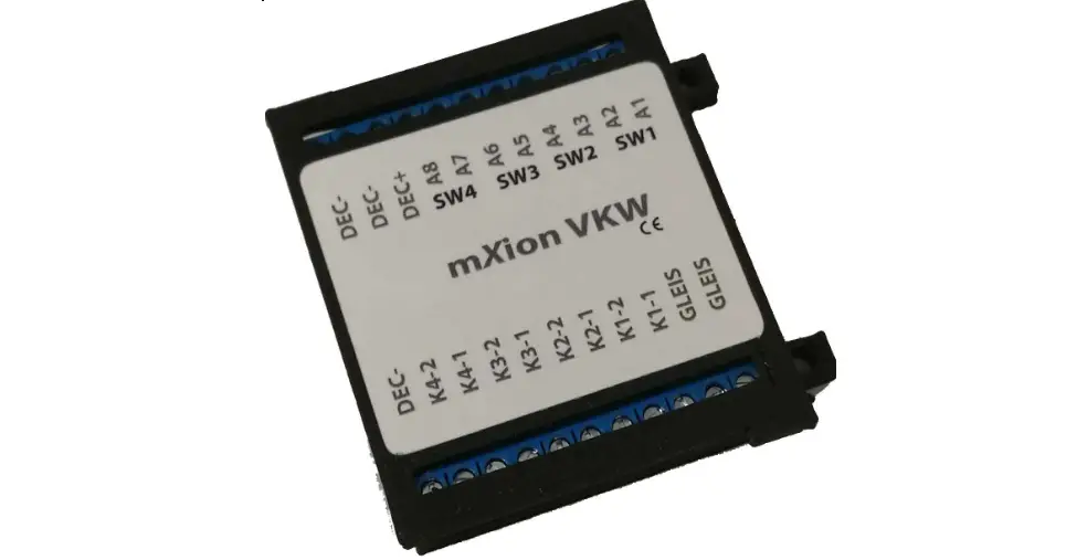
Connectors
DCC/MM switch
At operation, programming switch, change direction for start programming send desired address switch back to normal state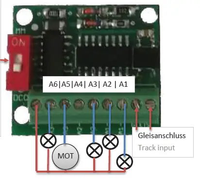
Product description
The mXion USD is a very small but powerful 6 ch. switch decoder for universal use.
He offers various programmable functions like flashing, pairwise flashing and over
16 other effects (18 in total). This includes simulations such as TV, Neon, Petroleum, Welding, US lights and much more. The effects are great for street lamps, even entire streets, houses and much more and also with the SDF combined!
The special thing about this decoder is that integrated SDF. With this system (known from our FSD decoder) you can now stationary
the 6 channel use for chases (14 integrated), fun fair (2x integrated), lively house, construction site and much more ideal for funfairs, buildings and so on.
The 6 turnout addresses can be independently programm and do not need each other be following. In addition to the usual CV programming also supports the module a programming switch to quickly get the addresses to be able to change.
The module supports DCC and Motorola, so this decoder can be used universally.
Fairy mode
Another special feature of the decoder is the SDF and thus the fair, running lights and site feature. This is described in CV19 set. Switched via F1 (CV21). So owns the decoder 15 chases with various patterns, construction site running lights, speed cameras and much more. On top of that
2 finished fairground events integr. (15/16).
Programming lock
To prevent accidental programming to prevent CV 15/16 one programming lock. Only if CV 15 = CV 16 is a programming possible. Changing CV 16 changes automatically also CV 15.
With CV 7 = 16 can the programming lock reset.
STANDARD VALUE CV 15/16 = 245
Programming options
This decoder supports the following programming types: bitwise, POM and CV read & write and register-mode.
There will be no extra load for programming.
In POM (programming on maintrack) the programming lock is also supported. The decoder can also be on the main track programmed without the other decoder to be influenced. Thus, when programming the decoder can not be removed.
NOTE: To use POM without others decoder must affect your digital center POM to specific decoder adresses
Programming binary values
Some CV’s (e.g. 29) consist of so-called binary values. The means that several settings in a value. Each function has a bit position and a value. For
programming such a CV must have all the significances can be added. A disabled function has always the value 0.
EXAMPLE: You want 28 drive steps and long loco address. To do this, you must set the value in CV 29 2 + 32 = 34 programmed.
Programming switch adress
Switch addresses consist of 2 values.
For addresses < 256 the value can be directly in address low. The high address is 0. If the address is > 255 this is as follows (for example address 2000):
2000 / 256 = 7,81, address high is 7
2000 – (7 x 256) = 208, address low is then 208.
About the programming button:
Change the position of the slider during operation, the point output 1 will alternate in 1 sec. clocking.
Switch on the desired control unit on the control unit switch address, then output 1 will alternate faster (0,5 sec). In order to the address has been accepted correctly and all 3 outputs are numbered.
You can now put the slider back on the switch the original state. The protocol can not be changed during operation become!
Reset functions
The decoder can be reset via CV 7. Various areas can be used for this purpose. Write with the following values:
- 11 (basic functions)
- 16 (programming lock CV 15/16)
- 33 (function outputs)
CV-Table
S = Default, L = Loco address, S = Switch address, LS = Loco and switch address usable
| CV | Description | S | L/S | Range | Note | |
| 7 | Software version | – | – | read only (10 = 1.1) | ||
| 7 | Decoder reset functions | |||||
| 3 ranges available | 11 16 33 | basic settings (CV 1,11-13,17-19,29-119) programming lock (CV 15/16) function- & Switch outputs (CV 120-139) | ||||
| 8 | Manufacturer ID | 160 | – | read only | ||
| 7+8 | Register programming mode | |||||
| Reg8 = CV-Address Reg7 = CV-Value | CV 7/8 don’t changes his real value CV 8 write first with cv-number, then CV 7 write with value or read (e.g.: CV 49 should have 3) è CV 8 = 49, CV 7 = 3 writing | |||||
| 9 | SDF-House time min in minute | 3 | S | 1 – 255 | minimal time for reload rate | |
| 10 | SDF- House time max in minute | 15 | S | 1 – 255 | maximum time for reload rate | |
| 12 | Random generator | 0 | W | 0 – 255 | Add value to the CV for function 0 = deactive +1 = A1, +2 = A2, +4 = A3, +8 = A4, +16 = A5, +32 = A6 | |
| 15 | Programming lock (key) | 165 | S | 0 – 255 | to lock only change this value | |
| 16 | Programming lock (lock) | 165 | S | 0 – 255 | changes in CV 16 will change CV 15 | |
| 17 | SDF time for function | 10 | S | 0 – 255 | time base (10 ms / value) | |
| 18 | Switch address calculation | 0 | S | 0/1 | 0 = Switch adress like norm 1 = Switch adress like Roco, Fleischmann | |
| 19 | Specialdecoderfunctions (SDF) | 0 | S | see attachment 2, switchable w. A1 0 = deactive, normal function for A1-A6 else SDF effect active | ||
| 20 | A1 switch address high | 0 | S | 1 – 2048 | switch output 1, if address smaller 256 easy programm CV21 = desired address! | |
| 21 | A1 switch address low | 1 | S | |||
| 22 | A1 dimming value | 100 | S | 1 – 228 | dimming value in % (1 % ca. 0,2 V) +128 = fading | |
| 23 | A1 special function | 0 | S | see attachment 1 | ||
| 24 | A1 time for special function | 5 | S | 1 – 255 | time base (0,1s / value) | |
| 25 | A2 switch address high | 0 | S | 1 – 2048 | switch output 2, if address smaller 256 easy programm CV26 = desired address! | |
| 26 | A2 switch address low | 2 | S | |||
| 27 | A2 dimming value | 100 | S | 1 – 228 | dimming value in % (1 % ca. 0,2 V) +128 = fading | |
| 28 | A2 special function | 0 | S | see attachment 1 | ||
| 29 | A2 time for special function | 5 | S | 1 – 255 | time base (0,1s / value) | |
| 30 | A3 switch address high | 0 | S | 1 – 2048 | switch output 3, if address smaller 256 easy programm CV31 = desired address! | |
| 31 | A3 switch address low | 3 | S | |||
| 32 | A3 dimming value | 100 | S | 1 – 228 | dimming value in % (1 % ca. 0,2 V) +128 = fading | |
| 33 | A3 special function | 0 | S | see attachment 1 | ||
| 34 | A3 time for special function | 5 | S | 1 – 255 | time base (0,1s / value) | |
| 35 | A4 switch address high | 0 | S | 1 – 2048 | switch output 4, if address smaller 256 easy programm CV36 = desired address! | |
| 36 | A4 switch address low | 1 | S | |||
| 37 | A4 dimming value | 100 | S | 1 – 228 | dimming value in % (1 % ca. 0,2 V) +128 = fading | |
| 38 | A4 special function | 0 | S | see attachment 1 | ||
| 39 | A4 time for special function | 5 | S | 1 – 255 | time base (0,1s / value) | |
| 40 | A5 switch address high | 0 | S | 1 – 2048 | switch output 5, if address smaller 256 easy programm CV41 = desired address! | |
| 41 | A5 switch address low | 2 | S | |||
| 42 | A5 dimming value | 100 | S | 1 – 228 | dimming value in % (1 % ca. 0,2 V) +128 = fading | |
| 43 | A5 special function | 0 | S | see attachment 1 | ||
| 44 | A5 time for special function | 5 | S | 1 – 255 | time base (0,1s / value) | |
| 45 | A6 switch address high | 0 | S | 1 – 2048 | switch output 6, if address smaller 256 easy programm CV46 = desired address! | |
| 46 | A6 switch address low | 3 | S | |||
| 47 | A6 dimming value | 100 | S | 1 – 228 | dimming value in % (1 % ca. 0,2 V) +128 = fading | |
| 48 | A6 special function | 0 | S | see attachment 1 | ||
| 49 | A6 time for special function | 5 | S | 1 – 255 | time base (0,1s / value) | |
| ATTACHMENT 1 – Special function | |||
| Value | Application | Note | |
| 0 | no special function (normal output) | ||
| 1 | flash symetric | time base (0,1s / value) | |
| 2 | flash asymetric short ON (1:4) | time base (0,1s / Value) is for the long value | |
| 3 | flash a symetric long ON (4:1) | ||
| 4 | Photographer flash | time base (0,25s / value) | |
| 5 | monoflop (automatic switch off) | time base (0,1s / value) | |
| 6 | switch on delayed | time base (0,1s / value) | |
| 7 | firebox | ||
| 8 | TV flickering | ||
| 9 | petroleum flickering | ||
| 10 | flourescent tube | ||
| 11 | defective flourescent tube | ||
| 12 | alternating flash to paired output | in combination with second output (e.g. A1 & A2, A3 & A4) | |
| 13 | US strobelight | ||
| 14 | US double strobelight | ||
| 15 | US marslight | time base (0,1s / value) | |
| 16 | US ditch light | in combination with second output (e.g. A1 & A2, A3 & A4), 1st output normal light, 2nd ditch light function | |
| 17 | sodium lamp | ||
| 18 | welding light | use with blue led | |
| +32 | add switch off delayed | add value to function | |
| +64 | add switch on delayed | add value to function | |
| +128 | invers | add value to function | |
| ATTACHMENT 2 – SDF lightcontrol | |||
| Value | Application | Note | |
| 0 | no special function (normal output) | ||
| 1 – 14 | running light (differnt templates) | time base (10 ms / value) | |
| 15 | fairground 1 | time base (10 ms / value) | |
| 16 | fairground 2 (mXion KLM) | ||
| 18 | construction side light simulation | A6 = flasher | |
| 19 | flash lights | time base (10 ms / value) | |
| 21 | moving house (A1-A6 lights, A7 = bath, A8 = TV) | rate = time base | |
Technical data
- Power supply: 7-27V DC/DCC 5-18V AC
- Current: 5mA (with out functions)
- Maximum function current:
- Switch 1-6 each 0.5 Amps.
- Maximum current: 1.5 Amps.
- Temperature range: -40 up to 85°C
- Dimensions L*B*H (cm): 2.5*2.7*1
NOTE: In case you intend to utilize this device below freezing temperatures, make sure it was stored in a heated environment before operation to prevent the generation of condensed water. During operation is sufficient to prevent condensed water.
Warranty, Service, Support
micron-dynamics warrants this product against defects in materials and workmanship for one year from the original date of purchase. Other countries might have different legal warranty situations. Normal wear and tear, consumer modifications as well as improper use or installation are not covered. Peripheral component damage is not covered by this warranty. Valid warrants claims will be serviced without charge within the warranty period. For warranty service please return the product to the manufacturer. Return shipping charges are not covered by micron-dynamics. Please include your proof of purchase with the returned good. Please check our website for up to date brochures, product information, documentation and software updates. Software updates you can do with our updater or you can send us the product, we update for you free.
Errors and changes excepted.
Hotline
For technical support and schematics for application examples contact:
- micron-dynamics
- [email protected]
- [email protected]


