![]() GLD
GLD
User manual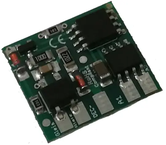
Introduction
Dear customer, we strongly recommend that you read these manuals and the warning notes thouroughly before installing and operating your device. The device is not a toy (15+).
NOTE: Make sure that the outputs are set to appropriate value before hooking up any other device. We can’t be responsible For any damage if this is disregarded.
NOTE: This decoder can be controlled via a switch address (up to 255) if CV 29 Bit 7 = 1 is set (from V. 1.1). Control old LGB and H0 switches with 3 poles. You need to set CV49 Bit 6,7 one of them to 1 (invers).
General information
We recommend studying this manual thoroughly before installing and operating your new device.
Place the decoder in a protected location.
The unit must not be exposed to moisture.
NOTE: Some funktions are only available with the latest firmware.
Please make sure that your device is programmed with the latest firmware.
Summary of Funktions
DC/AC/DCC operation
Analog & digital
Compatible NMRA-DCC module
Very small module
Switchable with accesoir addresses (3 pol)
Buffer compatible
2 reinforced function outputs
Random generator (e.g. toilet light)
Conditions (forward, backward, etc…)
Lot of special and time functions available
Function outputs dimmable
Reset function for all CV values
Easy function mapping
28 function keys programmable, 10239 loco
14, 28, 128 speed steps (automaticly)
Multiple programming options
(Bitwise, CV, POM)
Needs no programming load
Controllable with switch addresses (V. 1.1)
Scope of supply
Manual
mXion GLD
Hook-Up
Install your device in compliance with the connecting diagrams in this manual.
The device is protected against shorts and excessive loads. However, in case of a connection error e.g. a short this safety feature can’t work and the device will be destroyed subsequently.
Make sure that there is no short circuit caused by the mounting screws or metal.
NOTE: Please note the CV basic settings in the delivery state.
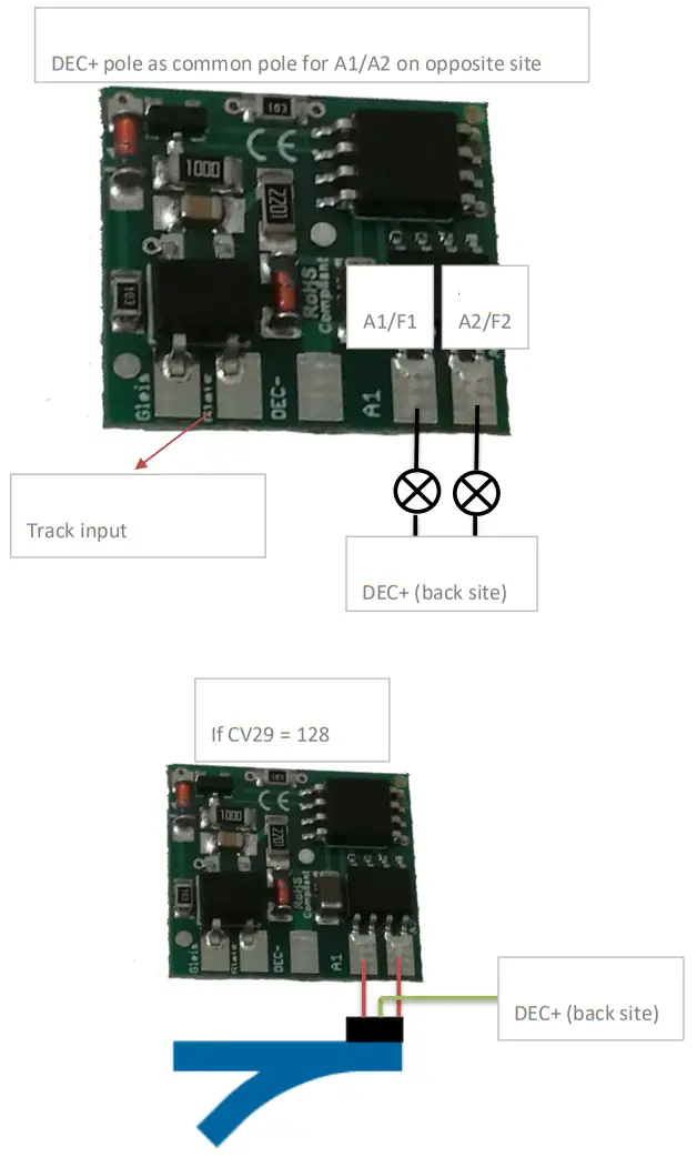
Connectors GLD
Switch loads between A1/A2 and common + pole.
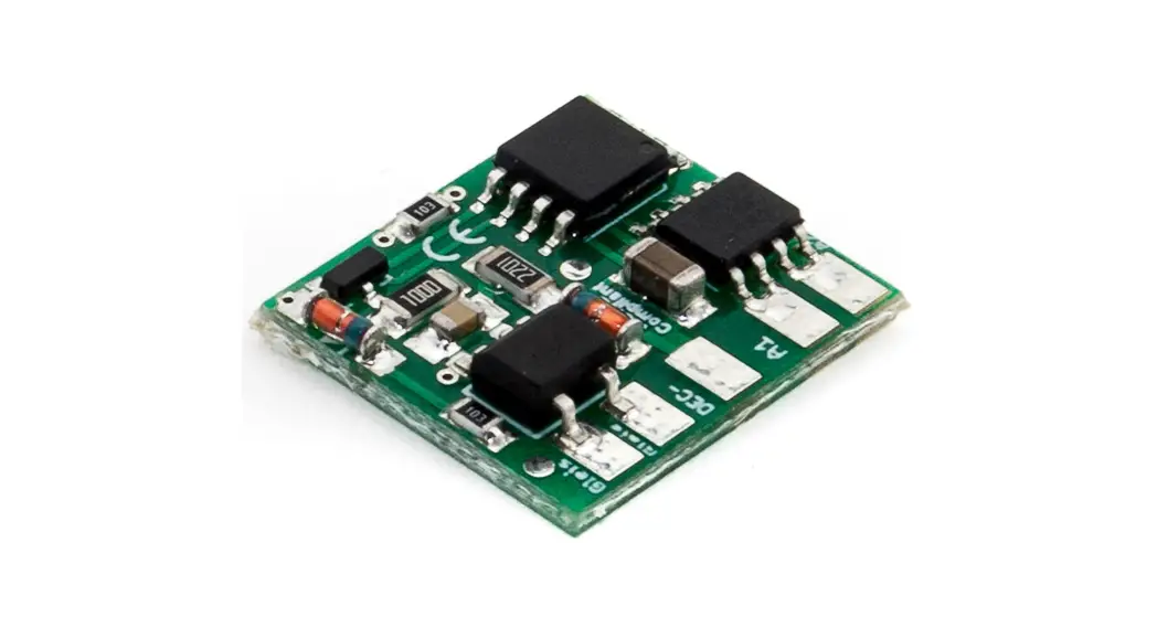
Product description
The mXion GLD is a 2 channel function decoder. It is due the high functionality and performance. Due to the small dimensions, the module (also multiple) in locomotives, cars, or buildings will. With its high power output from to 1 Amps per channel it is ideally suited to even larger loards. Furthermore, the module supports a series of lighting and switching effects configured and freely customizable.
It is ideal for passenger cars to suit these to light up and with light effects to be equipped. The two channels can, for example, compartments separately lit.
Train closing lamps.
In analog mode, both outputs are full functionality also usable.
In addition, both outputs can be dimmed.
The GLD-decoder can be used in all LGB® cars excellent and easy without mods.
The following pictures show various LGB® car models installed (invisible even!).
LGB® (from top to ground) unit wagon and into the LGB® HSB wagon. 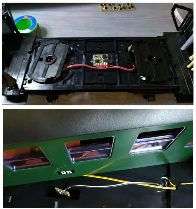
Programming lock
To prevent accidental programming to prevent CV 15/16 one programming lock. Only if CV 15 = CV 16 is a programming possible. Changing CV 16 changes automatically also CV 15.
With CV 7 = 16 can the programming lock reset.
STANDARD VALUE CV 15/16 = 245
Programming options
This decoder supports the following programming types: bitwise, POM and CV read & write and register-mode.
There will be no extra load for programming.
In POM (programming on maintrack) the programming lock is also supported.
The decoder can also be on the main track programmed without the other decoder to be influenced. Thus, when programming the decoder can not be removed.
NOTE: To use POM without others decoder must affect your digital center POM to specific decoder adresses
Programming binary values
Some CV’s (e.g. 29) consist of so-called binary values. The means that several settings in a value. Each function has a bit position and a value. For programming such a CV must have all the significances can be added. A disabled function has always the value 0.
EXAMPLE: You want 28 drive steps and long loco address. To do this, you must set the value in CV 29 2 + 32 = 34 programmed.
Buffer control
Connect buffer directly DEC+ and DEC-.
The capacitors need, provided no charging electronics is included, with a resistor of 120 ohms and a diode in parallel between DEC+ and the port (+) of the buffer be switched. The dash on the diode (cathode) must be connected to DEC- become. The decoder contains none buffer control unit.
Programming loco adress
Locomotives up to 127 are programmed directly to CV 1. For this, you need CV 29 Bit 5 „off“ (will set automaticly).
If larger addresses are used, CV 29 – Bit 5 must be „on“ (automaticly if change CV 17/18). The address is now in CV 17 and CV 18 stored. The address is then like follows (e.g. loco address 3000):
3000 / 256 = 11,72; CV 17 is 192 + 11 = 203.
3000 – (11 x 256) = 184; CV 18 is then 184.
Reset functions
The decoder can be reset via CV 7. Various areas can be used for this purpose.
Write with the following values:
11 (basic functions)
16 (programming lock CV 15/16)
33 (function outputs)
Function output features
| Funktion | A1 | A2 | Timevalue |
| On/Off | X | X | |
| Deactivated | X | X | |
| Permanent-On | X | X | |
| Forwards only | X | X | |
| Backwards only | X | X | |
| Standing only | X | X | |
| Driving only | X | X | |
| Timer sym. flash | X | X | X |
| Timer asym. short | X | X | X |
| Timer asym. long | X | X | X |
| Monoflop | X | X | X |
| Switch on delay | X | X | X |
| Firebox | X | X | |
| TV flickering | X | X | |
| Photographer flash | X | X | X |
| Petroleum flickering | X | X | |
| Flourescent tube | X | X | |
| defective flour. tube | X | X | |
| US strobe light | X | X | X |
| US double strobe | X | X | X |
| Pairwise alternating | X | X | X |
| Fade in/out | |||
| Autom. switch back | X | ||
| Dimmable | X | X |
CV-Table
S = Default, A = Analog operation usable
| CV | Description | S | A | Range | Note | ||
| 1 | Loco address | 3 | 1 – 127 | if CV 29 Bit 5 = 0 (automatically reset) | |||
| 7 | Software version | – | – | read only (10 = 1.0) | |||
| 7 | Decoder reset functions | ||||||
| 3 ranges available | 11 16 33 | basic settings (CV 1,11-13,17-19,29-119) programming lock (CV 15/16) function outputs (CV 120-129) | |||||
| 8 | Manufacturer ID | 160 | – | read only | |||
| 7+8 | Register programming mode | ||||||
| Reg8 = CV-Address Reg7 = CV-Value | CV 7/8 don’t changes his real value CV 8 write first with cv-number, then CV 7 write with value or read (e.g.: CV 49 should have 3) → CV 8 = 49, CV 7 = 3 writing | ||||||
| 11 | Analog timeout | 30 | 30 – 255 | 1ms each value | |||
| 13 | Function outputs in analog mode (on if value is set) |
3 |
0 – 3 | add the values to the desired function! A1 = 1, A2 = 2 | |||
| 15 | Programming lock (key) | 245 | 0 – 255 | to lock only change this value | |||
| 16 | Programming lock (lock) | 245 | 0 – 255 | changes in CV 16 will change CV 15 | |||
| 17 | Long loco address (high) | 128 | 128 – 10239 | activ only if CV 29 Bit 5 = 1 (automatically set if change CV 17/18) | |||
| 18 | Long loco address (low) | ||||||
| 19 | Traction address | 0 | 1 – 127/255 | loco address for multi traction 0 = deactive, +128 = invers | |||
| 29 | NMRA configuration | 6 | √ | bitwise programming | |||
| Bit | Value | OFF (Value 0) | ON | ||||
| 1 | 2 | 14 speed steps | 28/128 speed steps | ||||
| 2 | 4 | only digital operation | digital + analog operation | ||||
| 5 | 32 | short loco address (CV 1) | long loco address (CV 17/18) | ||||
| 7 | 128 | loco address | switch address (from V. 1.1) | ||||
| 48 | Switch address calculation (V. 1.1) | 0 | S | 0/1 | 0 = Switch adress like norm 1 = Switch adress like Roco, Fleischmann | ||
| 49 | mXion configuration | 0 | √ | bitwise programming | |||
| Bit | Value | OFF (Value 0) | ON | ||||
| 4 | 16 | A1 normal | A1 fading in/out (ab. V. 1.4) | ||||
| 5 | 32 | A2 normal | A2 fading in/out (ab. V. 1.4) | ||||
| 6 | 64 | A1 normal | A1 invers (from V. 1.1) | ||||
| 7 | 128 | A2 normal | A2 invers (from V. 1.1) | ||||
| 98 | Random generator | 0 | √ | 0 – 3 | Add for function, +1 = A1, +2 = A2 (V. 1.1) | ||
| 19 | GLD | ||||||
| CV | Description | S | A | Range | Note |
| 120 | A1 command allocation | 1 | see attachment 1 (if CV 29 Bit 7 = 1, switch address up to 255 (from V. 1.1)) | ||
| 121 | A1 dimming value | 255 | √ | see attachment 2 | |
| 122 | A1 condition | 0 | √ | see attachment 3 (from V. 1.1) | |
| 123 | A1 special function | 0 | √ | see attachment 4 | |
| 124 | A1 time for special function | 5 | √ | 1 – 255 | time base (0,1s / value) |
| 125 | A2 command allocation | 2 | see attachment 1 (if CV 29 Bit 7 = 1, switch address up to 255 (from V. 1.1)) | ||
| 126 | A2 dimming value | 255 | √ | see attachment 2 | |
| 127 | A2 condition | 0 | √ | see attachment 3 (from V. 1.1) | |
| 128 | A2 special function | 0 | √ | see attachment 4 | |
| 129 | A2 time for special function | 5 | √ | 1 – 255 | time base (0,1s / value) |
| ATTACHMENT 1 – Command allocation | ||
| Value | Application | Note |
| 0 – 28 | 0 = Switch with light key 1 – 28 = Switch with F-key | Only if CV 29 Bit 7 = 0 |
| +64 | permanent off | |
| +128 | permanent on | |
| ATTACHMENT 2 – Dimming value | ||
| Value | Application | Note |
| 0 – 255 | dimming value | in % (1 % is around 0,2 V) |
| ATTACHMENT 3 – Condition | ||
| Value | Application | Note |
| 0 | permanent (normal function) | |
| 1 | forward only | |
| 2 | backward only | |
| 3 | standing only | |
| 4 | standing „forward“ only | |
| 5 | standing „backward“ only | |
| 6 | driving only | |
| 7 8 | driving „forward“ only driving „backward“ only | |
| ATTACHMENT 4 – Special function | ||
| Value | Application | Note |
| 0 | no special function (normal output) | |
| 1 | flash symetric | time base (0,1s / value) |
| 2 | flash asymetric short ON (1:4) | time base (0,1s / Value) is for the long value |
| 3 | flash a symetric long ON (4:1) | |
| 4 | Photographer flash | time base (0,25s / value) |
| 5 | monoflop (automatic switch off) | time base (0,1s / value) |
| 6 | switch on delayed | time base (0,1s / value) |
| 7 | firebox | |
| 8 | TV flickering | |
| 9 | petroleum flickering | |
| 10 | flourescent tube | |
| 11 | defective flourescent tube | |
| 12 | alternating flash to paired output | in combination A1 & A2 |
| 13 | US strobe light | time base (0,1s / value) |
| 14 | US double strobe light | time base (0,1s / value) |
Technical data
Power supply: 7-27V DC/DCC
5-18V AC
Current: 5mA (with out functions)
Maximum function current:
| A1 | 1 Amps. |
| A2 | 1 Amps. |
Maximum current: 1 Amps.
Temperature range: -20 up to 65°C
Dimensions L*B*H (cm): 2*1.5*0.5
NOTE: In case you intend to utilize this device below freezing temperatures, make sure it was stored in a heated environment before operation to prevent the generation
of condensed water. During operation is sufficient to prevent condensed water.
Warranty, Service, Support
micron-dynamics warrants this product against defects in materials and workmanship for one year from the original date of purchase. Other countries might have different legal warranty situations. Normal wear and tear, consumer modifications as well as improper use or installation are not covered.
Peripheral component damage is not covered by this warranty. Valid warrants claims will be serviced without charge within the warranty period. For warranty service please return the product to the manufacturer. Returnshipping charges are not covered by micron-dynamics. Please include your proof of purchase with the returned good. Please check our website for up to date brochures, product information, documentation and software updates. Software updates you can do with our updater or you can send us the product, we update for you free.
Errors and changes excepted.
Hotline
For technical support and schematics for application examples contact:
micron-dynamics
[email protected]
[email protected]
www.micron-dynamics.de
https://www.youtube.com/@micron-dynamics