MOXA ICF-1170I Series Field to Fiber Converter Installation Guide

Overview
Introduction
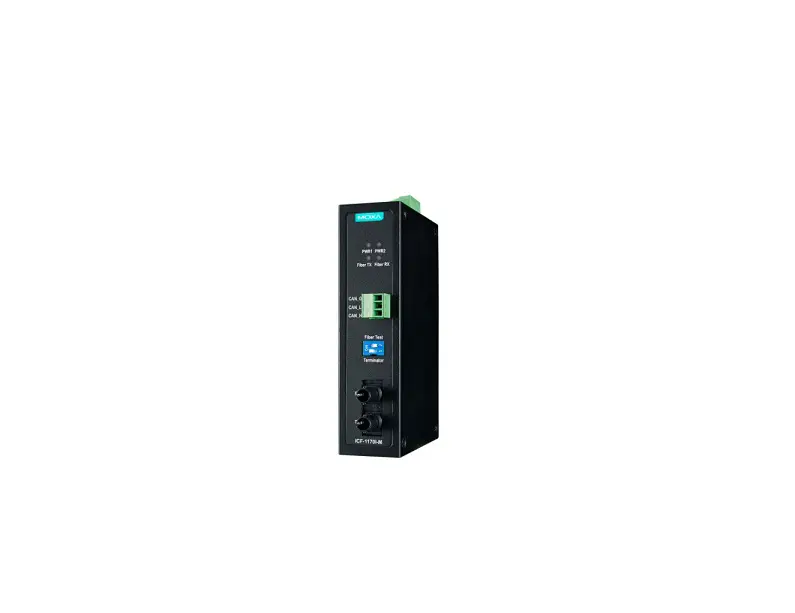
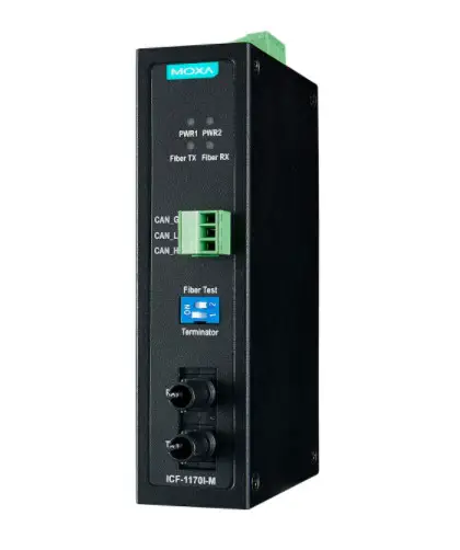
The ICF-1170I series is a CAN-to-fiber optic converter that secures data transmission by using fiber optic transmission to provide complete isolation and protection against EMI.
The ICF-1170I series can separate and protect critical segments of the system from the rest of the CAN network and is protocol independent, allowing it to work with all of the different CAN protocols and frame lengths.
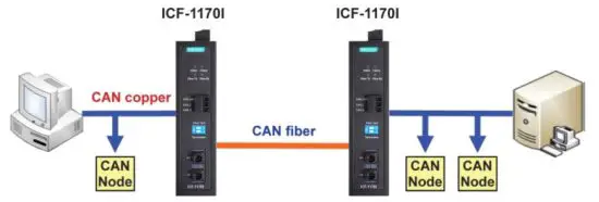
To connect two CAN devices with fiber optic cable, two ICF-1170I series converters are required.
Why Convert CAN to Fiber?
• IMMUNITY FROM ELECTRICAL INTERFERENCE
Fiber is not affected by electromagnetic interference or radio frequency interference; consequently it provides a clean communication path and is immune to crosstalk.
• INSULATION
Optical fiber is an insulator; the glass fiber eliminates the need for using electric current as the communication medium.
• SECURITY
Optical fiber provides better security compared to traditional electrical signals transmitted through a wire or radio waves transmitted through the air. Since the light rays travel down the center of the fiber, it is extremely difficult for them to escape. In addition, it is nearly impossible to tap into a fiber optic cable, and even if a tap is successful, it is possible to detect the tap by monitoring the optical power received at the termination point.
• RELIABILITY AND MAINTENANCE
Fiber is immune to adverse temperature and moisture conditions, does not corrode or lose its signal, and is not affected by short circuits, power surges, or static electricity.
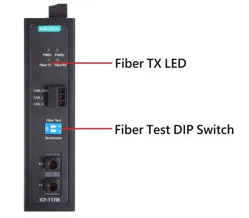
Fiber Test Mode
The ICF-1170I supports a special feature called Fiber Test Mode, which is easily activated with a DIP switch on the ICF-1170I’s outer panel.
Fiber Test Mode can be used to test the fiber cable between two
ICF-1170I units and provides a simple way to determine if the fiber cable is transmitting data correctly.
When in Fiber Test Mode, the fiber transceiver (TX) will send out a data signal continuously and the “Fiber TX” LED will light up. On the other side of the connection, when the ICF-1170I fiber transceiver (RX) receives the data signal form the TX side, the “Fiber RX” LED will light up.
Alarm Contact Output
The ICF-1170I supports dual power inputs for redundancy. When one power input fails, the relay will be triggered. Be sure to install the dual power inputs for the ICF-1170I series, and choose the correct relay output when connecting the alarm.
Features
- Transmission distance up to 2 km
- Convert CAN signals to fiber and fiber to CAN signals
- CAN transfer rate up to 1 Mbps
- Dual power inputs for redundancy
- DIP switch for 120 Ω terminal resistance
- DIP switch for fiber test mode
- Wide temperature range model available for -40 to 85°C environments
Package Checklist
Before installing the ICF-1170I series, verify that the package contains the following items:
- ICF-1170I series CAN-to-fiber Converter
- Quick Installation Guide (printed)
- Warranty card
NOTE: Please notify your sales representative if any of the above items are missing or damaged.
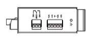
Mounting Dimensions (Unit: mm)
ICF-1170I-M-ST
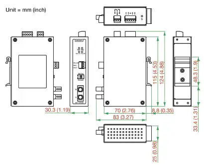
Top View
Front View
ATTENTION
Electrostatic Discharge Warning!
To protect the product from damage due to electrostatic discharge, we recommend wearing a grounding device when handling your ICF-1170 series.
Mounting
The aluminum DIN-rail attachment plate should be fixed to the back panel of the ICF-1170I series when you take it out of the box. If you need to reattach the DIN-rail attachment plate to the ICF-1170I, make sure the stiff metal spring is situated towards the top, as shown in the figures below.
Step 1:
Insert the top of the DIN-rail into the slot just below the stiff metal spring.
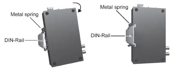
Step 2:
The DIN-rail attachment unit will snap into place as shown below
To remove the ICF-1170I series from the DIN-rail, simply reverse Steps 1 and 2 above.
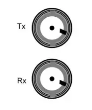
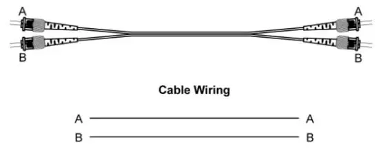
Fiber Cable
ST-Port Pinouts ST-Port to ST-Port Cable Wiring
 ATTENTION
 ATTENTION
This is a Class 1 laser/LED product. Do not stare into the laser beam.
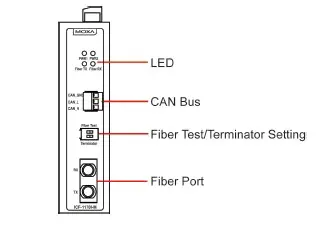
Switch Settings
There are two DIP switches on the front panel of the ICF-1170I series.
| 120 Ω Terminator | Switch 1 |
| Enable | ON |
| Disable | OFF (default) |
| Fiber Test Mode | Switch 2 |
| Enable | ON |
| Disable | OFF (default) |
LED Indicators
There are 4 LEDs on the front panel of the ICF-1170I.
| LED | Color | Function |
| PWR 1 | Green | Steady ON: Power source 1 is ON. |
| PWR 2 | Green | Steady ON: Power source 2 is ON. |
| Fiber Tx | Green | When sending CAN data to the fiber port. |
| Fiber Rx | Orange | When receiving CAN data from the fiber port. |
Typical CAN Application
Transmission Length
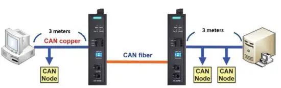
The maximum length for CAN fiber is 2 km (depending on the data rate and the protocol used). This table below suggests the maximum fiber lengths at certain baud rates as per ISO-11989-2 while using no more than 3m of the CAN Bus cable in the CAN bus network
| Baud Rate | Fiber Length |
| 1000 kbps | 10 m |
| 500 kbps | 100 m |
| 250 kbps | 250 m |
| 125 kbps | 400 m |
| 50 kbps | 1000 m |
| 10 kbps | 2000 m |
NOTE The transmission distance is limited by the signal rate, as stated in the ISO 11898-2 standard
Specifications
| CAN Communication | |
| CAN Bus Interface | ISO 11898-2, Terminals (CAN_H, CAN_L, CAN_GND) |
| Protocols Supported | CAN 2.0A and 2.0B (ISO 11898-2) |
| CAN Connector | 3-pin removable screw terminal x1 |
| Termination Resistor | Dip switch selector for 120 Ω terminal resistor |
| Baudrate | Up to 1 Mbps |
| System Delay | 150 ns |
| Isolation Protection | 2 KV |
| LED Indicators | PWR1, PWR2, Fiber TX, Fiber RX |
| Fiber Communication | |
| Connector Type | ST (multimode) fiber ports x 2 |
| Support Cable | 50/125, 62.5/125, or 100/140 μm (multimode) |
| Wavelength | 850 nm |
| TX Output | > -5 dBm |
| RX Sensitivity | -20 dBm |
| Environmental Limits | |
| Operating Temperature | 0 to 60°C (32 to 140°F), 5 to 95 % RH -40 to 85°C (-40 to 185°F) for -T model |
| Storage Temperature | -40 to 85°C (-40 to 185°F), 5 to 95 % RH |
| Power | |
| Input Power Voltage | 12 to 48 VDC dual power input for redundancy |
| Alarm contact | 1 normal open/close output with current-carrying capacity of 1 A@24 VDC |
| Mechanical Specifications | |
| Dimensions | 30.3 × 70 × 115 mm |
| Material | Aluminum (1 mm) |
| Gross Weight | 135 g |


