MOXA TCF-142 Series Serial-To-Fiber Converters
Introduction
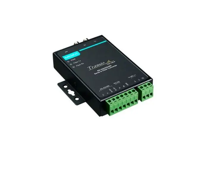
TCF-142 series converters are equipped with a multiple interface circuit that can handle RS-232, RS-422, and RS-485 serial interfaces, as well as multi-mode or single-mode fiber. TCF-142 converters are used to extend serial transmission distance up to 5 km (TCF-142-M, with multi-mode fiber) or up to 40 km (TCF-142-S, with single-mode fiber). The TCF-142 must be configured to transmit a particular serial interface. You cannot transmit both RS-232 and RS-485 signals at the same time.
Why Convert Serial to Fiber?
Fiber communication not only extends the communication distance, but also provides many advantageous features.
IMMUNITY FROM ELECTRICAL INTERFERENCE: Fiber is not affected by electromagnetic interference or radio frequency interference. It provides a clean communication path and is immune to cross-talk.
INSULATION: Optical fiber is an insulator; the glass fiber eliminates the need for using electric currents as the communication medium.
SECURITY: Fiber cannot be tapped by conventional electric means and is very difficult to tap into optically.
RELIABILITY & MAINTENANCE: Fiber is immune to adverse temperature and moisture conditions, does not corrode or lose its signal, and is not affected by short circuits, power surges, or static electricity.
Reverse Power Protection
The Reverse Power Protection feature provides extra protection against accidentally connecting the power cables to the wrong terminal. The converter automatically detects which power wire is positive and which is negative.
Ring Mode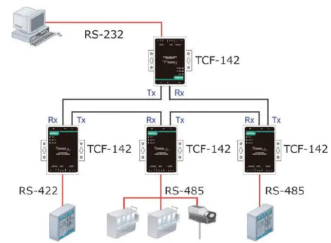 To allow one half-duplex serial device to communicate with multiple half-duplex devices connected to a fiber ring, you should configure the TCF-142 for “ring mode” by setting DIP switch “SW4” to the “On” position. The Tx port of a particular TCF-142 unit connects to the neighboring converter’s Rx port on the ring. Note that when one node transmits a signal, the signal travels around the ring until it returns back to the transmitting unit, which then blocks the signal. Users should ensure that the total fiber ring length is less than 100 km when using either single-mode models (TCF-142-S) or multi-mode models (TCF-142-M).
ATTENTION
For Fiber Ring Users:
To avoid problems when setting up a fiber ring, each TCF-142 unit making up the ring must be powered down and set to “Ring mode.” Next, make sure all cables are connected properly, and then power up all devices connected to the ring.
NOTE “Ring Mode” can only be used with half-duplex applications (i.e., RS-485 multi-drop communication).
DIP Switch Selectable Terminator
The TCF-142’s termination resistor is set with a DIP switch located on the outside of the converter’s casing.
No Configuration Required for Baudrate Settings
The TCF-142 is compatible with any baudrate from 50 bps to 921.6 kbps. The TCF-142 automatically converts the signal back and forth between serial (RS-232, RS-422, or RS-485) and fiber, and does not need to interpret the signal or the baudrate of the transmitting device. For this reason, the TCF-142 does not have any DIP switches or jumpers for setting the baudrate.
Features
- “Ring” or “Point to Point” transmission
- Extend RS-232/422/485 transmission distance:
- up to 40 km with single-mode—TCF-142-S Series
- up to 5 km with multi-mode—TCF-142-M Series
- Compact size
- Decrease signal interference
- Protect against electronic degradation and chemical corrosion
- Supports baudrates up to 921.6 kbps
- Extended operating temperature from -40 to 75°C (for “T” models)
Package Checklist
Before installing the TCF-142, verify that the package contains the following items:
- 1 TCF-142 media converter
- Power jack to 3-pin terminal block adaptor
- Stick-on pads
- Quick installation guide (printed)
- Warranty card
NOTE: Please notify your sales representative if any of the above items are missing or damaged.
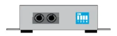
Dimensions and Appearance
TCF-142 fiber converters are easy to set up and use. The serial terminal block of one of the converters connects to your computer, the serial terminal block of the other converter connects to your serial device, and the two converters are connected by fiber cable(s).
NOTE Electrostatic Discharge Warning!
To protect the product from damage due to electrostatic discharge, we recommend wearing a grounding device when handling your TCF-142.
TCF-142-M/S-ST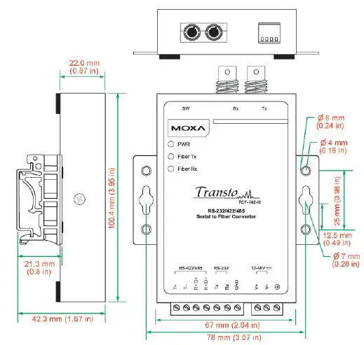
TCF-142-M/S-SC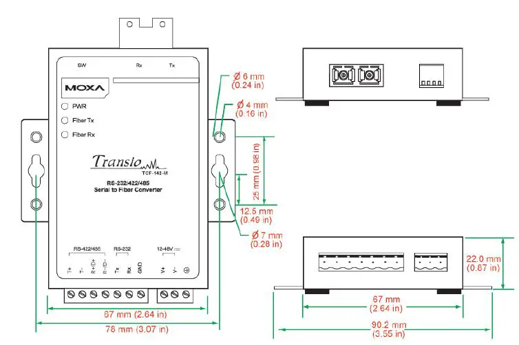
Wiring Examples
Connecting the Power Supply
Before using the TCF-142, first connect the DC power supply to the power supply terminal block located on the TCF-142’s bottom panel.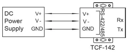
Connecting RS-422 and 4-wire RS-485 Serial Devices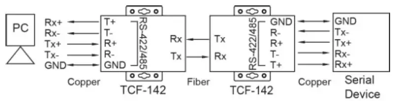
Connecting 2-wire RS-485 Serial Devices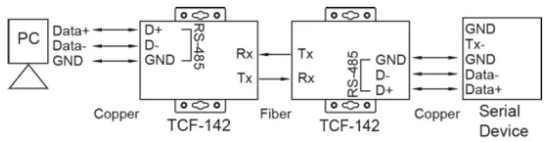
Connecting an RS-232 Serial Device to a PC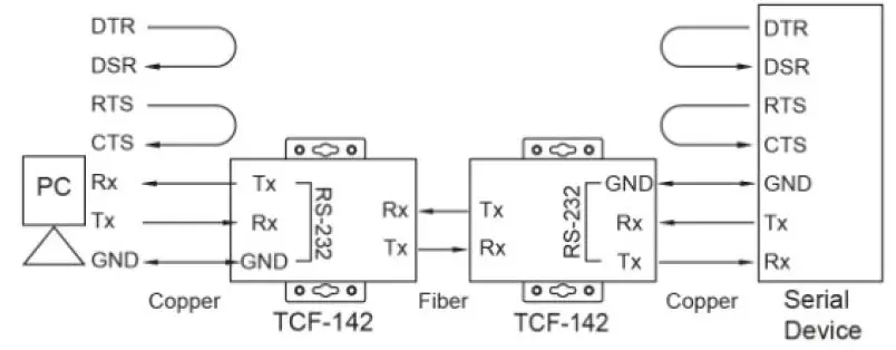
Switch Settings 
| Serial Connection | SW1 | SW2 |
| RS-232 | ON | OFF |
| RS-422 | ON | ON |
| RS-485 4-wire | OFF | OFF |
| RS-485 2-wire | OFF | ON |
| Built-in 120 Ω Terminator | SW3 | SW4 |
| Enable | ON | – |
| Disable | OFF | – |
| Ring mode | – | ON |
| Point to Point mode | – | OFF |
NOTE This switch setting is used for product revision 3.2 or later; for previous revisions, refer to the label on the product’s rear panel for the correct information. The S1 DIP Switch is located inside the TCF-142. When the TCF-142 is in RS-485 mode, use this DIP switch to configure RS-485 data direction control, data format, and baudrate. When the TCF-142 is in RS-232/422 mode, the S1 DIP switch cannot affect RS-232/422 communication. 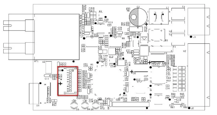
RS-485 Data Direction Control Settings
| RS-485 Data Direction Control | S1 Pin 1 |
| Auto Baudrate | OFF |
| Fixed Baudrate | ON |
Data Format Settings
| Data Format | S1 Pin 2 | S1 Pin 3 | S1 Pin 4 |
| 7 Bits | OFF | ON | ON |
| 8 Bits | ON | OFF | ON |
| 9 Bits | OFF | OFF | ON |
| 10 Bits | ON | ON | OFF |
| 11 Bits | OFF | ON | OFF |
| 12 Bits | ON | OFF | OFF |
Baudrate Settings
| Baudrate | S1 Pin 5 | S1 Pin 6 | S1 Pin 7 | S1 Pin 8 | S1 Pin 9 |
| 50 | OFF | ON | ON | ON | ON |
| 75 | ON | OFF | ON | ON | ON |
| 110 | OFF | OFF | ON | ON | ON |
| 134.5 | ON | ON | OFF | ON | ON |
| 150 | OFF | ON | OFF | ON | ON |
| 300 | ON | OFF | OFF | ON | ON |
| 600 | OFF | OFF | OFF | ON | ON |
| 1200 | ON | ON | ON | OFF | ON |
| 1800 | OFF | ON | ON | OFF | ON |
| 2400 | ON | OFF | ON | OFF | ON |
| 4800 | OFF | OFF | ON | OFF | ON |
| 7200 | ON | ON | OFF | OFF | ON |
| 9600 | OFF | ON | OFF | OFF | ON |
| 19200 | ON | OFF | OFF | OFF | ON |
| 38400 | OFF | OFF | OFF | OFF | ON |
| Baudrate | S1 Pin 5 | S1 Pin 6 | S1 Pin 7 | S1 Pin 8 | S1 Pin 9 |
| 57600 | ON | ON | ON | ON | OFF |
| 115200 | OFF | ON | ON | ON | OFF |
| 230400 | ON | OFF | ON | ON | OFF |
| 460800 | OFF | OFF | ON | ON | OFF |
| 921600 | ON | ON | OFF | ON | OFF |
The S2 DIP switch is located inside the TCF-142. This switch is used to configure the pull high/low resistors. Note that S2 Pin 1 and Pin 2 must both be configured to ON or both must be configured to OFF.
| Pull High/Low Resistor | S2 Pin 1* | S2 Pin 2* |
| 150K | OFF | OFF |
| 1K (default) | ON | ON |
NOTE We recommend setting S2 Pin 1 and Pin 2 to the 1K option (ON/ON) when termination is enabled.
LED Description
There are 3 LEDs on the front panel of the TCF-142.
| LED | Color | Function |
| PWR | Red | Steady ON: Power is ON |
| Fiber Tx | Green | Blinking when fiber is transmitting data |
| Fiber Rx | Orange | Blinking when fiber is receiving data |
Specifications
| Model Names | TCF-142-M-ST TCF-142-M-ST-T TCF-142-M-SC TCF-142-M-SC-T TCF-142-S-ST TCF-142-S-ST-T TCF-142-S-SC TCF-142-S-SC-T |
| Serial Communication | |
| Signals for RS-232 | TxD, RxD, SGND |
| Signals for RS-422 | TxD+, TxD-, RxD+, RxD-, SGND |
| Signals for 4-wire RS-485 | TxD+, TxD-, RxD+, RxD-, SGND |
| Signals for 2-wire RS-485 | Data+, Data-, SGND |
| Baudrate | 50 bps to 921.6 kbps |
| Surge protection | 15 kV ESD |
| Fiber Communication | |
| Connector type | ST or SC |
| Distance | TCF-142-S series: Single mode fiber for 40 km TCF-142-M series: Multi mode fiber for 5 km |
| Cable Specifications | TCF-142-S series: 8.3/125, 8.7/125, 9/125 or 10/125 μm TCF-142-M series: 50/125, 62.5/125, or 100/140 μm |
| Wavelength | TCF-142-S series: 1310 nm TCF-142-M series: 850 nm |
| TX Output | TCF-142-S series: > -5 dBm TCF-142-M series: > -5 dBm |
| RX Sensitivity | TCF-142-S series: -25 dBm TCF-142-M series: -20 dBm |
| Point-to-Point Transmission | Half or Full duplex |
| Ring Transmission | Half duplex |
| Environmental Limits | |
| Operating Temperature | 0 to 60°C (32 to 140°F), 5 to 95 % RH |
| Extended Operating Temperature (T models) | -40 to 75°C (-40 to 167°F) |
| Storage Temperature | -40 to 75°C (-40 to 167°F), 5 to 95 % RH |
| Power | |
| Input Power Voltage | 12 to 48 VDC |
| Power Line Protection | 1 kV Burst (EFT), EN61000-4-4 1 kV Surge, EN61000-4-5 |
| Reverse Power Protection | Protects against V+/V- reversal |
| Over Current Protection | Protects against 2 signals shorted together: 1.1A |
| Power Consumption | 140 mA at 12 VDC 67.7 mA at 24 VDC 28.7 mA at 48 VDC |
| Physical Characteristics | |
| Dimensions | 67 x 100 x 22 mm 90 x 100 x 22 mm (including ears) |
| Material | Aluminum (1 mm) |
| Gross Weight | 320 g |
| Regulatory Approvals | |
| EMC | CE, FCC (Class A) |
| LVD | EN 60950-1 |
| Safety | UL 60950-1 |
| EMI | FCC Part 15 Subpart B Class B, EN 55032 Class B |
| EMS | EN61000-4-2 (ESD), Criteria B, Level 2 EN61000-4-3 (RS), Criteria B, Level 2 EN61000-4-4 (EFT), Criteria B, Level 2 EN61000-4-5 (Surge), Criteria B, Level 2 EN61000-4-6 (CS), Criteria B, Level 2 |


