MOXA ICF-1150 Series Serial-to-Fiber Converters
Introduction
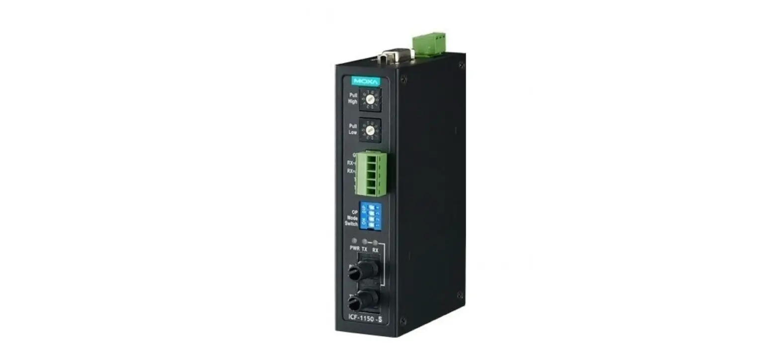
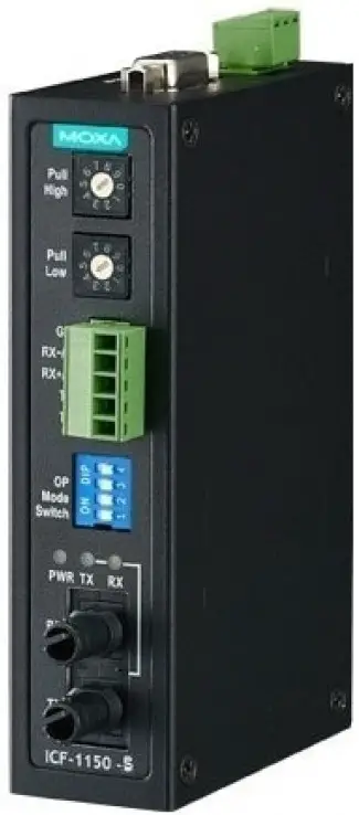
The ICF-1150 series of fiber converters has a multi-interface circuit that can handle RS-232 and RS-422/485 serial interfaces, as well as multi-mode or single-mode fiber. ICF-1150 series converters extend serial transmission distance up to 5 km (ICF-1150-M, with multi-mode fiber) or up to 40 km (ICF-1150-S, with single-mode fiber).
Why Convert Serial to Fiber?
Fiber communication not only extends the communication distance but also provides many helpful features.
IMMUNITY FROM ELECTRICAL INTERFERENCE:
Fiber is not affected by electromagnetic interference and radio frequency interference. It provides a clean communication path and is immune to cross-talk.
INSULATION:
Optical fiber is an insulator; glass fiber eliminates the need for using electric currents as the communications medium.
SECURITY:
Fiber cannot be tapped by conventional electronic means and is very difficult to tap into optically. Furthermore, radio and satellite communication signals can be captured easily for decoding.
RELIABILITY & MAINTENANCE:
Fiber is immune to adverse temperature and moisture conditions do not corrode or lose its signal and is not affected by short circuits, power surges, or static electricity.
Reverse Power Protection
The Reverse Power Protection feature provides extra protection against accidentally connecting the power cables to the wrong terminal. The converter detects automatically which power wire is positive and which is negative, and then adjusts the power supply accordingly.
3-Way Communication
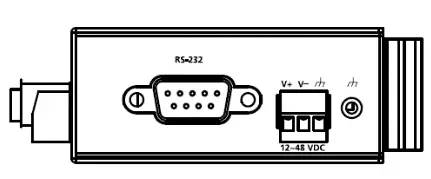
The ICF-1150 series supports 2 serial ports. The D-sub connector is for RS-232 communication and the removable terminal block is for RS-422 or RS-485 communication. The 3 ports (2 serial ports and one fiber port) are completely independent. When the ICF-1150 series converters receive data from any port, it will send data out through the other 2 ports. For example, when the ICF-1150 series converters receive a command from the remote Master via the fiber port, it will convert the command and transmit it via the RS-232 port and RS-422/485 port at the same time. So if the user is trying to monitor a system running on the RS-485 network, there is no need to use an additional RS-232 to RS-485 converter to connect the laptop computer’s serial port to the RS-485 bus.
ATTENTION
The ICF-1150 is designed to receive data from one port and send data to the other ports. If the ICF-1150 receives data from 2 ports at the same time, a data error may occur on all the RX ports.
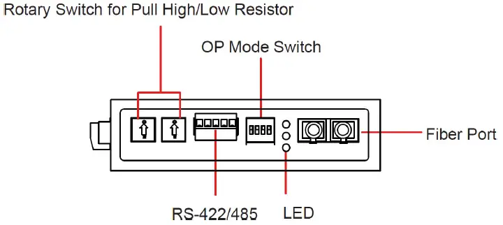
Rotary Switch for Setting the Pull Up/Down Resistor
Since the RS-485 port can support multi-drop connections or daisy-chain connections, system engineers can connect meters, RTUs, readers, and many other devices together on the same bus. The impedance of the data line will rise according to the number of serial devices on the same bus. To get the system working, the ICF-1150 has a setting for tuning the pull-up/down resistor. Just turn the dial to find the best resistor value for the system without removing the ICF-1150 from the DIN rail. (The default settings are 1k for both switches.)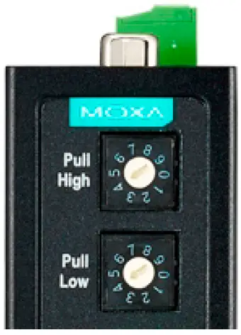
Pull Up/Down Resistor
| Position | 0 | 1 | 2 | 3 | 4 | 5 | 6 | 7 | 8 | 9 |
| Ohms | 150k | 10k | 4.7k | 3.3k | 1k | 909 | 822 | 770 | 500 | 485 |
DIP Switch for Selectable Terminator
The termination resistor for many products of this type is set by a jumper located inside the product’s casing. To disable or change the resistor’s strength, the user must open the casing to reset the jumper. Moxa offers a more user-friendly solution that allows users to set the termination resistor with a DIP switch located outside the ICF-1150 converter’s casing.
No Configuration Required for Baudrate Settings
The ICF-1150 works under any baudrate from 50 bps to 921.6 kbps. The ICF-1150 simply converts the signal back and forth between serial (RS-232, RS-422, or RS-485) and fiber. Since the ICF-1150 does not need to interpret the signal, it does not need to know the baudrate of the transmitting device.
NOTE
The ICF-1150I default setting is auto-baudrate. If you need to use the fixed baudrate, then you will need to use the DIP switch to do the configuration.
Ring Mode
To allow one half-duplex serial device to communicate with multiple half-duplex devices connected to a fiber ring, configure the ICF-1150 for “ring mode” by setting DIP switch “SW3” to the “On” position. The Tx port of a particular ICF-1150 unit connects to the neighboring converter’s Rx port to form the ring. Note that when one node transmits a signal, the signal travels around the ring until it returns to the transmitting unit, which then blocks the signal. Users should ensure that the total fiber ring length is less than 100 km when using either single-mode models or multi-mode models.
Features
- “Ring” or “Point to Point” transmission
- Extend RS-232/422/485 transmission distance:
- up to 40 km with single-mode—ICF-1150-S series
- up to 5 km with multi-mode—ICF-1150-M series
- Supports baud rates up to 921.6 kbps
- 3-way galvanic isolation (for –I models)
- Wide operating temperature from -40 to 85°C (for “T” models)
- C1D2, ATEX, and IECEx certified for harsh industrial environments
Package Checklist
Before installing the ICF-1150, verify that the package contains the following items:
- ICF-1150 fiber converter
- Quick installation guide (printed)
- Warranty card
NOTE
Please notify your sales representative if any of the above items are missing or damaged.
Mounting Dimensions (unit: mm)
ICF-1150-SC
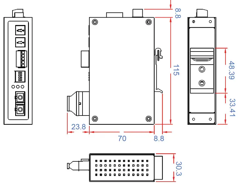
ICF-1150-ST
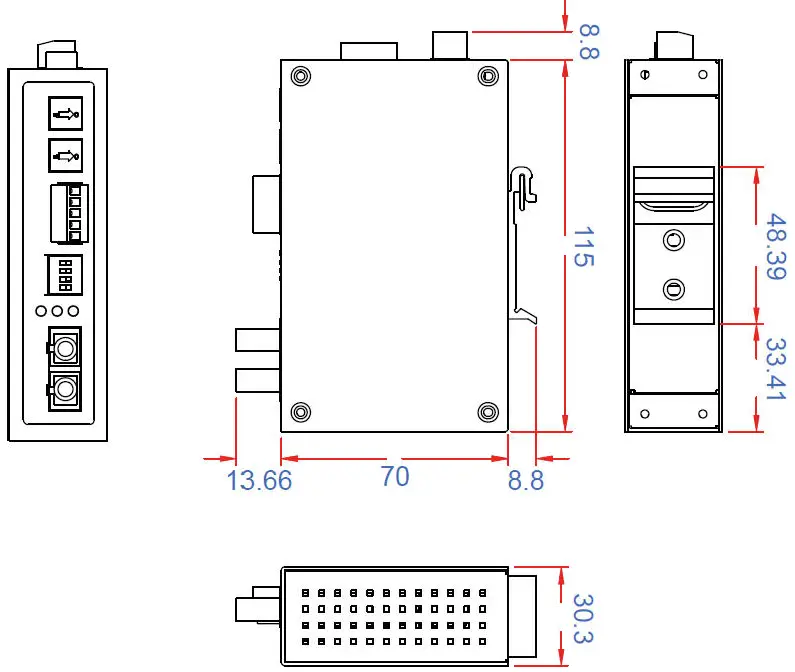
Top View
Front View
ATTENTION
Electrostatic Discharge Warning!
To protect the product from damage due to electrostatic discharge, we recommend wearing a grounding device when handling your ICF-1150 product.
Mounting (in an enclosure or industrial panel)
The aluminum DIN rail attachment plate should be fixed to the back panel of the ICF-1150 when you take it out of the box. If you need to reattach the DIN rail attachment plate to the ICF-1150, make sure the stiff metal spring is situated towards the top, as shown in the figures below.
STEP 1:
Insert the top of the DIN rail into the slot just below the stiff metal spring.
STEP 2:
The DIN rail attachment unit will snap into place as shown below.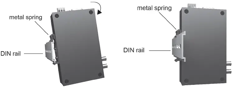
To remove the ICF-1150 series from the DIN rail, simply reverse Steps 1 and 2 above.
Pin Assignment
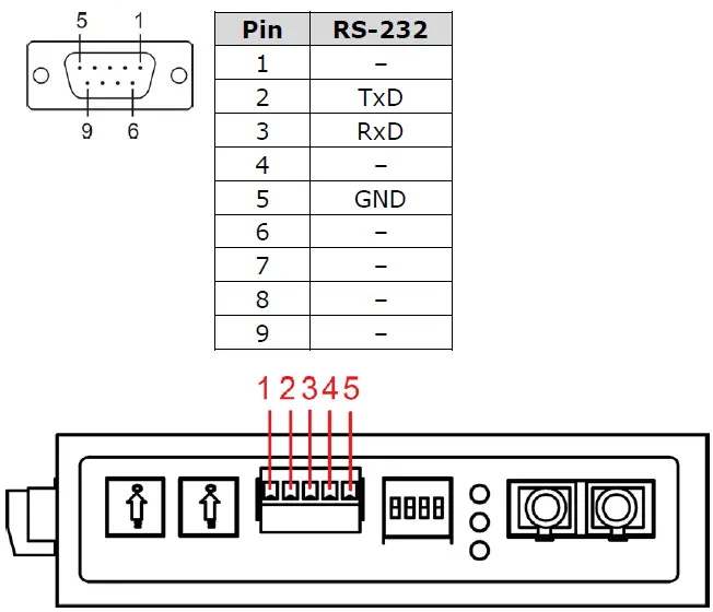
| Pin | RS-422 | 4-wire RS-485 | 2-wire RS-485 |
| 1 | GND | GND | GND |
| 2 | Rx- | Rx- | Data – |
| 3 | Rx + | Rx + | Data + |
| 4 | Tx – | Tx – | – |
| 5 | Tx + | Tx + | – |
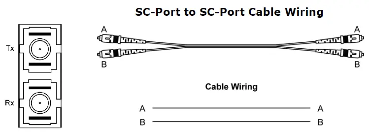
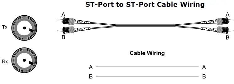
Fiber Cable
SC-Port Pinouts
ST-Port Pinouts
ATEX and IECEx Information
- Certification number: DEMKO 10 ATEX 0917344X IECEx UL 13.0044X
- Ambient range:
Model Ambient Temp. Range Models without suffix “-T” 0 to 60°C Models with suffix “T” -40 to 85°C - Certification string: Ex ec IIC T4 Gc
- Standards covered: EN IEC 60079-0:2018, EN IEC 60079-7: 2015 + A1:2018
- IEC 60079-0, Edition 7, IEC 60079-7, Edition 5.1Conditions of safe usage:
- The Ethernet communication devices must be mounted in a tool-accessible IP54 enclosure in accordance with IEC/EN 60079-0 and used in an area of not more than pollution degree 2 as defined by IEC/EN 60664-1.
- Provisions shall be made to prevent transient disturbances should exceed the rated voltage by over 140%.
- The Terminal blocks (J1, J2) are suitable for 14 to 28 AWG (3.31-0.08 mm2), with torque = 1.7 lb-in. The cross-sectional area of the PE conductor is Sp=3.31 mm2. The conductor used for grounding is 12 AWG minimum.
- Conductors suitable for use in an ambient temperature of 91°C must be used for the power supply terminal.
ATTENTION
This is a Class 1 laser/LED product. Do not stare into the laser beam.
Federal Communications Commission Statement
FCC:
This device complies with part 15 of the FCC Rules. Operation is subject to the following two conditions:
- This device may not cause harmful interference, and
- This device must accept any interference received, including interference that may cause undesired operation.
Switch Settings
There are 4 DIP switches on the front panel of the ICF-1150.
| Setting | Switch 1 | Switch 2 |
| RS-422 | ON | OFF |
| 2-wire RS-485 | OFF | ON |
| 4-wire RS-485 | OFF (default) | OFF (default) |
| Fiber Mode | Switch 3 |
| Ring Mode | ON |
| Point to Point mode | OFF (default) |
| 120Ω Terminator | Switch 4 |
| Enable | ON |
| Disable | OFF (default) |
For Fiber Ring Users:
If the Rx LEDs of the converter glow continuously, remove the fiber cable and then reconnect. The Rx LEDs should no longer glow continuously.
NOTE: “Ring Mode” can only be used for half-duplex applications.
The S3 DIP Switch is located inside the ICF-1150. When the ICF-1150 is in RS-485 mode, use this DIP switch to configure RS-485 data direction control, data format, and baudrate. When the ICF-1150 is in RS-232/422 mode, the S3 DIP switch cannot affect RS-232/422 communication.
Direction Control and Data Format Setting
You will need to open the product’s casing to do the Direction Control and Data Format Setting.
NOTE
Direction Control and Data Format Setting require the model version v1.2.0 or later.
RS-485 Data Direction Control Settings
| RS-485 Data Direction Control | S3 Pin 1 |
| Auto Baudrate | OFF |
| Fixed Baudrate | ON |
Data Format Settings
| Data Format | S3 Pin 2 | S3 Pin 3 | S3 Pin 4 |
| 7 Bits | OFF | ON | ON |
| 8 Bits | ON | OFF | ON |
| 9 Bits | OFF | OFF | ON |
| 10 Bits | ON | ON | OFF |
| 11 Bits | OFF | ON | OFF |
| 12 Bits | ON | OFF | OFF |
The serial data format includes one start bit, between five and eight data bits, and one stop bit. A parity bit and an additional stop bit might be included in the format as well.
For example
8-N-1 is interpreted as eight data bits, with no parity bit, and one stop bit. Users need to adjust the DIP switch to set the data format to 10 bits.
| Baudrate | S3 Pin 5 | S3 Pin 6 | S3 Pin 7 | S3 Pin 8 | S3 Pin 9 |
| 50 | OFF | ON | ON | ON | ON |
| 75 | ON | OFF | ON | ON | ON |
| 110 | OFF | OFF | ON | ON | ON |
| 134.5 | ON | ON | OFF | ON | ON |
| 150 | OFF | ON | OFF | ON | ON |
| 300 | ON | OFF | OFF | ON | ON |
| 600 | OFF | OFF | OFF | ON | ON |
| 1200 | ON | ON | ON | OFF | ON |
| 1800 | OFF | ON | ON | OFF | ON |
| 2400 | ON | OFF | ON | OFF | ON |
| 4800 | OFF | OFF | ON | OFF | ON |
| 7200 | ON | ON | OFF | OFF | ON |
| 9600 | OFF | ON | OFF | OFF | ON |
| 19200 | ON | OFF | OFF | OFF | ON |
| 38400 | OFF | OFF | OFF | OFF | ON |
| 57600 | OFF | ON | ON | ON | OFF |
| 115200 | OFF | ON | ON | ON | OFF |
| 230400 | ON | OFF | ON | ON | OFF |
| 460800 | OFF | OFF | ON | ON | OFF |
| 921600 | ON | ON | OFF | ON | OFF |
LED Indicators
There are 3 LEDs on the front panel of the ICF-1150.
| LED | Color | Function |
| PWR | Green | Steady ON: Power is ON |
| Fiber Tx | Green | When sending serial data from the fiber port |
| Fiber Rx | Yellow | When receiving data from the fiber port |
Specifications
| Serial Communication | |
| Signals for RS-232 | TxD, RxD, SGND |
| Signals for RS-422 | TxD+, TxD-, RxD+, RxD-, SGND |
| Signals for 4-wire RS-485 | TxD+, TxD-, RxD+, RxD-, SGND |
| Signals for 2-wire RS-485 | Data+, Data-, SGND |
| Baudrate | 50 bps to 921.6 Kbps |
| ESD protection | 15 kV ESD |
| Fiber Communication | |
| Connector type | ST or SC |
| Distance | Single-mode fiber for 40 km Multi-mode fiber for 5 km |
| Support Cable | Single mode: 8.3/125, 8.7/125, 9/125 or 10/125 μm Multi-mode: 50/125, 62.5/125, or 100/140 μm |
| Wavelength | ICF-1150-S: 1310 nm ICF-1150-M: 850 nm |
| TX Output | ICF-1150-S: > -8 dBm ICF-1150-M: > -8 dBm |
| RX Sensitivity | ICF-1150-S: -25 dBm ICF-1150-M: -25 dBm |
| Point-to-Point Transmission | Half or Full duplex |
| Multi-drop Transmission | Half duplex, fiber ring |
| Environmental | |
| Operating Temperature | 0 to 60°C (32 to 140°F), 5 to 95 % RH -40 to 85°C (-40 to 185°F) for –T Model |
| Storage Temperature | -40 to 85°C (-40 to 185°F), 5 to 95 % RH |
| Power | |
| Input Power Voltage | 12 to 48 VDC, 300 mA (Max.) Class 2 |
| Power Line Protection | 4 kV Burst (EFT), EN61000-4-4 4 kV Surge, EN61000-4-5 |
| Reverse Power Protection | Protects against V+/V- reversal |
| Over Current Protection | Protects against 2 signals shorted together: 1.1 A |
| Power Consumption | ICF-1150-S/M-SC/ST: 246 mA @ 12 V ICF-1150I-S/M-SC/ST: 300 mA @ 12 V |
| Physical Characteristics | |
| Dimensions (W × D × H) | 30.3 × 70 × 115 mm |
| Material | Aluminum (1 mm) |
| Gross Weight | ICF-1150 : 118g ICF-1150I : 135g |
| Regulatory Approvals | |
| CE | Class A |
| FCC | Part 15 sub Class A |
| EMI | EN55032, Class A |
| EMS | EN 61000-4-2 (ESD): Contact: 8 kV; Air: 15 kV EN 61000-4-3 (RS): 80 MHz to 1 GHz: 3 V/m EN 61000-4-4 (EFT): Power: 4 kV; Signal: 1 kV EN 61000-4-5 (Surge): |
| Power: 4 kV; Signal: 1 kV EN 61000-4-6 (CS): 150 kHz to 80 MHz: 3 V/m EN 61000-4-8 (PFMF) | |
| Freefall | IEC 60068-2-32 |
| MTBF | ICF-1150 : 2,298,766 hrs ICF-1150I : 1,770,450 hrs |
Pay specific attention to the following:
- For indoor use and pollution degree II, wipe with a dry cloth when cleaning up the labeling.
- Please use a qualified power supply by SELV or double insulation of UL60950 or UL61010-1 or UL61010-2-201 standards.
- UL61010-2-201: Shall be mounted in the Industrial Control Panel and the ambient temperature should not exceed 75 degree Celsius.
- If the equipment is used in a manner not specified by the manufacturer, then the protection provided by the equipment may be impaired.
- We suggest using the cable type 24 AWG (American Wire Gauge) and the corresponding pin-type cable terminals.
- We suggest using a torque value of 6.5 lb-in; do not use excessive force when fixing the wiring.
WARNING
EXPLOSION HAZARD. DO NOT CONNECT OR DISCONNECT WHEN ENERGIZED.
AVERTISSEMENT
RISQUE D’EXPLOSION. NE PAS BRANCHER NI DÉBRANCHER SOUS TENSION.
WARNING
EXPLOSION HAZARD. DO NOT REMOVE OR REPLACE WHILE THE CIRCUIT IS LIFE UNLESS THE AREA IS FREE OF IGNITIBLE CONCENTRATIONS
AVERTISSEMENT
RISQUE D’EXPLOSION. NE PAS RETIRER NI REMPLACER PENDANT QUE LE CIRCUIT EST SOUS TENSION À MOINS QUE L’EMPLACEMENT NE SOIT EXEMPT DE CONCENTRATIONS INFLAMMABLES.
Address of manufacturer: No. 1111, Heping Rd., Bade Dist., Taoyuan City 334004, Taiwan.
Technical Support Contact Information www.moxa.com/support.


