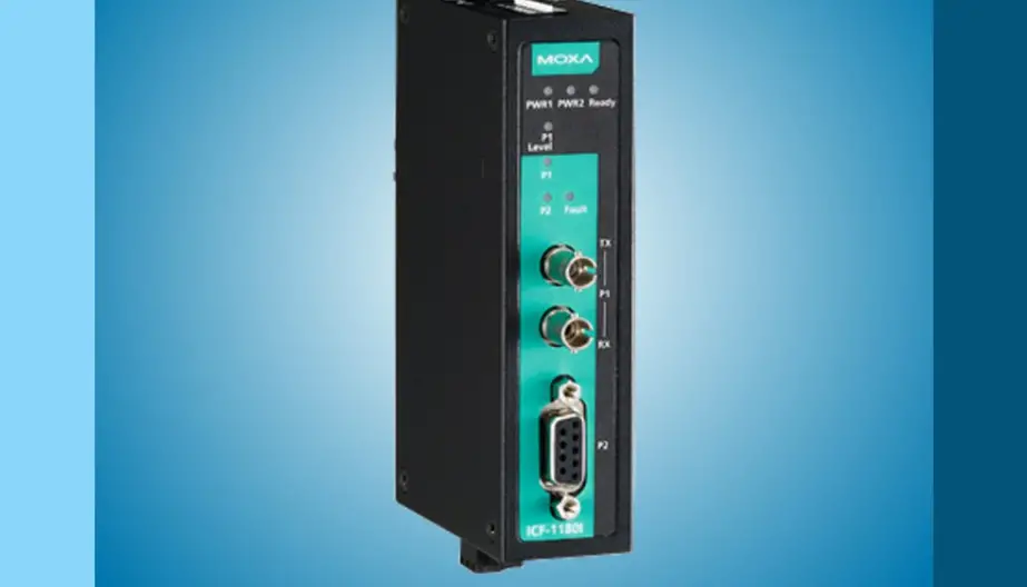
MOXA ICF-1171I Series Fieldbus-to-Fiber Converters
Introduction
The ICF-1171I Series CAN-to-fiber converters are used in pairs to connect two CAN (CAN 2.0) or two CAN FD (ISO CAN FD) devices or networks via single-mode or multi-mode optical fiber. The ICF-1171I CAN-to-fiber converters provide 2 kV isolation protection for the CAN interface and dual power inputs to ensure that your CAN system works uninterrupted.
The ICF-1171I Series can separate and protect critical segments of the system from the rest of the CAN network and is protocol independent, allowing it to work with all the different CAN protocols and frame lengths. In other words, the higher layer CAN protocols, based on CAN (CAN 2.0) and CAN FD (ISO CAN FD), can work through the ICF-1171I Series.
To connect two CAN devices with a fiber-optic cable, two ICF-1171I Series converters are required.
Why an ICF-1171I CAN-to-fiber converter?
- Extends the CAN Bus Transmission Distance
Typically, the total transmission distance of a CAN (CAN 2.0) or CAN FD (ISO CAN FD) system can be extended by 2 km (multi-mode fiber) or by 40 km (single-mode fiber) using ICF-1171I converters. However, the reach of these extensions depends on the environment, architecture, etc. - Easily Fulfil Various Communication Scenarios
Two CAN (CAN 2.0) networks or CAN FD (ISO CAN FD) networks can communicate with each other using different baud rates. The ICF-1171I converters can automatically detect the Baudrate of the connected CAN (CAN 2.0) device and apply the Baudrate itself. Therefore, you do not need to know the Baudrate of the connected CAN (CAN 2.0) device, making it an extremely convenient feature. Baudrate can also be set to a predefined value via rotary switches. Please note that Automatic Baudrate detection is only supported in CAN (CAN 2.0), not in CAN FD. - Easily Troubleshoot Communication Issues
It is easy to check if an issue exists on the CAN bus or the fiber link. The ICF-1171I converters come with LEDs that indicate the fiber link state, fiber communication status, CAN bus state, and CAN bus communication status.
Features
- Extends the transmission distance of the overall CAN bus system
- Converts CAN signals to fiber and vice versa
- Supports CAN (or CAN 2.0, including CAN 2.0A and CAN 2.0B) and its extension CAN FD (CAN Flexible Data Rate); conforms to the ISO 11898 standard
- CAN (CAN 2.0) and CAN FD (ISO CAN FD) arbitration rate (or nominal bit rate, arbitration bit rate) is up to 1 Mbps; data rate is up to 5 Mbps
- Dual power inputs for redundancy
- DIP switch for 120 Ω terminal resistance
- Wide temperature range model available for -40 to 75°C environments (“-T” models)
- Supports higher layer CAN protocols such as CANopen, DeviceNet, SAE J1939, etc.
- Supports point-to-point connection to another ICF-1171I
Package Checklist
Before installing the ICF-1171I Series, verify the package contains the following items:
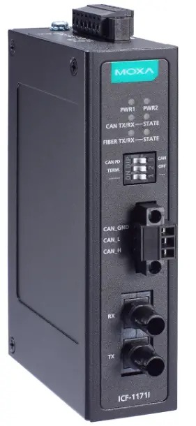
- ICF-1171I Series CAN-to-fiber converter with a DIN-rail kit pre-locked on it
- Quick Installation Guide (printed)
- Warranty card
Optional Accessory
- WK-30-02: Wall-mounting kit, 2 plates, 4 screws, 30 x 66.8 x 2 mm
NOTE Please notify your sales representative if any of the above items are missing or damaged.
Mounting Dimensions
ICF-1171I-S-ST/ICF-1171I-M-ST
The appearance is the same for all, including wide-temperature (-T) models; the only difference is the label of the model.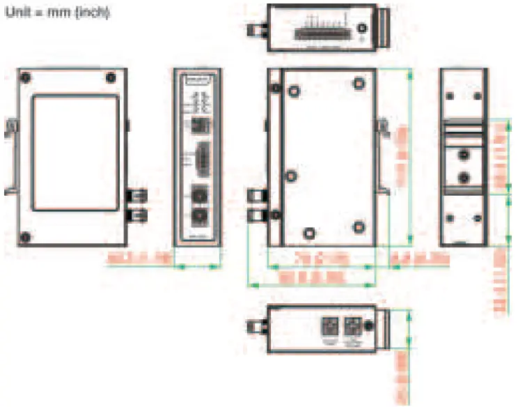
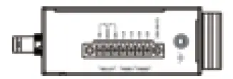
- Top View

- Front View

ATTENTION
Electrostatic Discharge Warning!
To protect the product from damage because of electrostatic discharge, we recommend wearing a grounding device when handling your ICF-1171I Series.
Hardware Installation Procedure
The ICF-1171I is designed to be attached to a DIN rail or mounted on a wall. For DIN-rail mounting, push down the spring and properly attach it to the DIN rail until it “snaps” into place. For wall mounting, install the wall-mount kit (optional) first and then screw the device onto the wall. An M3 screw is suggested, and the minimum length of the screw should be 7 mm.
The following figure illustrates the two suggested mounting options.
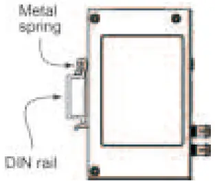
DIN-rail Installation
- Insert the top of the DIN-rail into the slot just below the stiff metal spring.

- The DIN-rail attachment unit will snap into place

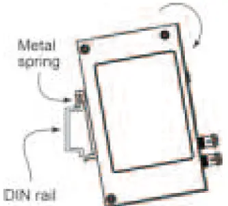
To remove the ICF-1171I Series from the DIN rail, simply reverse steps 1 and 2 above.
Wall-mounting Installation
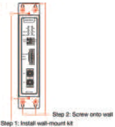 For wall mounting, the suggested direction of the product is upright—the same as for DIN-rail mounting.
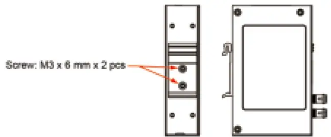
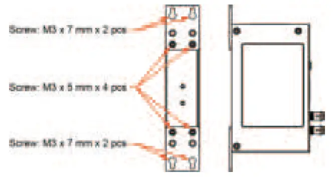
The following figure illustrates how to attach the screws to the mounting kits:
DIN Rail:
Wall-mount:
Power Input and Relay
The ICF-1171I supports dual power inputs for redundancy. When one power input fails, the relay will be triggered. Be sure to install the dual power inputs for the ICF-1171I Series and choose the correct relay output when connecting the alarm.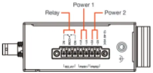 Please see the terminal block definition for power input and relay in the following table.
| Relay (Normally closed) | Relay (Common) | Relay (Normally open) | DC Power input 1 | DC Power input 1 | DC Power input 2 | DC Power input 2 |
| N.C. | COM | N.O. | V1+ | V1- | V2+ | V2- |
Please see the power input status and corresponding relay status in the following table:
| Power input status | Relay status |
| Both power inputs are on/off | Normally closed (N.C.) |
| Power input 1 or power input 2 is on | Normally open (N.O.) |
NOTE Before connecting the equipment to DC power inputs, make sure the DC power source voltage is stable
- The wiring of input terminal block shall be installed by a skilled person.
- Wire type: Cu
- Only use 28-14 AWG wire size, torque value 0.19 N-m.
- One individual conductor in a clamping point.
NOTE The equipment is intended to be supplied by the external power source (UL listed/ IEC 60950-1/ IEC 62368-1), which output complies with ES1/SELV, PS2/LPS, output rating is 12 to 48 VDC, 188.5 mA (max.), and ambient temperature 75°C
NOTE If you are using a Class I adapter, the power cord should be connected to an outlet with an earthing connection.
CAN Pin Assignment
Please see the terminal block definition for CAN bus port in the following table.
| CAN High | CAN Low | CAN Signal Ground |
| CAN_H | CAN_L | CAN_GND |
Make sure CAN high (CAN_H) is connected to the CAN high pin, and CAN low (CAN_L) is connected to the CAN low pin of your CAN device.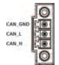
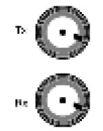
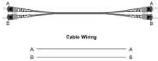
Fiber Cable
- ST-Port Pinouts

- ST-Port to ST-Port Cable Wiring

ATTENTION
This is a Class 1 laser/LED product. Do not stare into the laser beam.
- Caution—Use of the controls or adjustments or the performance of procedures other than those specified herein may result in hazardous radiation exposure.”
- Complies with 21 CFR 1040.10 and1040.11, except for conformance with IEC 60825-1 Ed. 3., as described in Laser Notice No. 56, dated May 8, 2019.
Switch Settings
There are three DIP switches on the front panel of the ICF-1171I Series; DIP switch 1 is reserved for future use. See the usage below.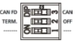 Use DIP switch 3 to set up CAN (CAN 2.0) or CAN FD (ISO CAN FD) mode. CAN in the table below is equal to CAN 2.0, and CAN FD is equal to ISO CAN FD.
| CAN Mode | Switch 3 |
| CAN FD | ON |
| CAN | OFF (default) |
Use DIP switch 2 to enable terminator.
| 120 Ω Terminator | Switch 2 |
| Enable | ON |
| Disable | OFF (default) |
There are two rotary switches at the bottom of the ICF-1171I Series, which is used to configure the arbitration rate or data rate of the CAN bus. Rotary switch 1 is used to set up the arbitration rate of CAN (CAN 2.0)/CAN FD (ISO CAN FD); rotary switch 2 is used to set up the data rate of CAN FD (ISO CAN FD).
Explore the following use cases to see how you use the rotary switches:
Use case 1: My devices use CAN (CAN2.0) with communication
speed/bit rate of 1Mbps. How do I set up the Baudrate of ICF-1171I?
You can set up a fixed Baudrate by switching rotary switch 1 to PIN 1, and ignore rotary switch 2. Or, you can use auto Baudrate by switching rotary switch 1 to PIN 0. When the ICF-1171I receives the data frames sent by the connected CAN device, it can detect the Baudrate and set to itself.
The auto Baudrate function sets up a sequence to initialize the baud rates supported by the ICF-1171I (e.g., 1Mbps, 800 kbps, 500kbps as in the table below).
Also, make sure the DIP switch in the front panel is set to “CAN” mode.
Use case 2: My devices use CAN FD (ISO CAN FD) with dual bit rates
(or called BRS, Bit Rate Switch), nominal/arbitration rate is 1Mbps, and data rate is 2Mbps.
In this case, please set rotary switch 1 to PIN 1, and set rotary switch 2 to PIN 3. Also, make sure the DIP switch in the front panel is set to
“CAN FD” mode.
Auto-Baudrate is supported in CAN (CAN 2.0). To use auto Baudrate, send the CAN data to the ICF-1171I. The ICF-1171I will detect the Baudrate and apply to itself.
| CAN 2.0/CAN FD Arbitration Rate | Rotary Switch 1 Pin Position |
| Auto baudrate (only in CAN 2.0) | 0 (Default) |
| 1 Mbps | 1 |
| 800 kbps | 2 |
| 500 kbps | 3 |
| 250 kbps | 4 |
| 125 kbps | 5 |
| 50* kbps | 6 |
| 25* kbps | 7 |
| Reserved | 8 |
| Reserved | 9 |
Arbitration rates 25 kbps and 50 kbps are only used in CAN (CAN 2.0); An arbitration rate equal to or above 125 kbps is supported in CAN FD (ISO CAN FD). For CAN FD (ISO CAN FD), the suggested ratio of arbitration rate to data rate ranges from 1:1 to 1:8.
| CAN FD Data Rate | Rotary Switch 2 Pin Position |
| 5 Mbps | 0 |
| 4 Mbps | 1 |
| 3 Mbps | 2 |
| 2 Mbps | 3 (Default) |
| 1 Mbps | 4 |
| 800 kbps | 5 |
| 500 kbps | 6 |
| 250 kbps | 7 |
| Reserved | 8 |
| Reserved | 9 |
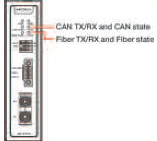
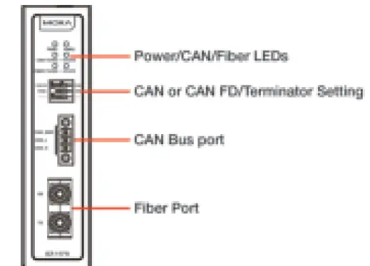
LED Indicators
There are 6 LEDs on the front panel of the ICF-1171I.
| LED | Color | Description |
| PWR1 | Green | Steady ON: Power is being supplied to PWR1 |
| Off | Off: Power is NOT being supplied to PWR1, or another type of other power error | |
| PWR2 | Green | Steady ON: Power is being supplied to PWR2 |
| Off | Off: Power is NOT being supplied to PWR2, or another type of power error | |
| CAN TX/RX | Green (Flashing) | CAN bus port is transmitting or receiving data |
| Off | No communication on CAN bus | |
| (CAN) STATE | Green | CAN is operating normally or the auto Baudrate detection is successful (According to the CAN definition, it’s called the Error active state; Transmit error counter or Receive error counter is below 127) |
| Red (Flashing once per second) | Communication errors have occurred (According to the CAN definition, it’s called the Error passive state; Transmit error counter or receive error counter equals or exceeds 127). Error Passive becomes Error Active when communication (transmission and reception) returns to normal, in other words, when both the TEC and the REC decrease to less than or equal to 127. To eliminate this error, check the following:
Resetting the ICF-1171I is not necessary in this case until it becomes Bus-Off. |
| LED | Color | Description |
| Red (Steady) | The Bus-Off state, or the auto Baudrate detection is unsuccessful (Bus-Off state: according to the CAN definition, when the transmit error count exceeds 255, a CAN node will enter the Bus-Off state.) When the LED is steady red, the reception/transmission of CAN messages is not possible. As there are two possible reasons for this condition, check the following to recover:
If this situation continues to happen, still check the following:
| |
| FIBER TX/RX | Green (Flashing) | The fiber port is transmitting or receiving CAN data |
| Off | No communication on fiber | |
| (Fiber) STATE | Green | The fiber signal is detected, and the link is on |
| Red | The fiber signal is not detected, or the link is off |
Typical Scenarios Using the ICF-1171I
Connecting two CAN or two CAN FD networks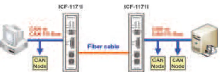
Extending Transmission Distance
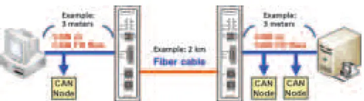 Typically, the total transmission distance of a CAN (CAN 2.0) or CAN FD (ISO CAN FD) system can be extended by 2 km (multi-mode fiber) or by 40 km (single-mode fiber) using ICF-1171I converters. Note that the ICF-1171I can be connected to another ICF-1171I in a point-to-point connection.
NOTE The transmission distance of the CAN bus side (not including the fiber side) is limited by the “Baudrate”, as stated in the ISO 11898 standard. The faster the Baudrate, the shorter the transmission distance.
Specifications
| CAN Communication | |
| CAN Bus Interface | ISO 11898, Terminals (CAN_H, CAN_L, CAN_GND) |
| Protocols Supported | DIP switch selector for CAN (CAN 2.0) and CAN FD (ISO CAN FD) (ISO 11898) |
| CAN Connector | 3-pin removable screw terminal |
| Termination Resistor | DIP switch selector for a 120-Ω terminal resistor |
| Baudrate | CAN (CAN 2.0): arbitration rate up to 1 Mbps (supports auto Baudrate) CAN FD (ISO CAN FD): arbitration rate up to 1 Mbps, data rate up to 5 Mbps (does not support auto Baudrate) |
| System Delay | 18 µs* for a pair of ICF-1171Is |
| *18 µs is tested under CAN 1Mbps, using one CAN device and one ICF- 1171I with a loopback fiber cable. | |
| Isolation Protection | 2 KV |
| LED Indicators | PWR1, PWR2, CAN TX/RX, CAN STATE, FIBER TX/RX, FIBER STATE |
| Receive Buffer | 8 data frames |
| Fiber Communication | |
| Connector Type | ST (single-mode and multi-mode), 100Base-FX |
| Cable Requirements | 9/125 μm (single-mode) or 62.5/125 μm (multi- mode) |
| Wavelength | 1310 nm (single-mode and multi-mode) |
| Tx Power | > -5 dBm (single-mode) or > -20 dBm (multi- mode) |
| Rx Range | -3 to -34 dBm (single-mode), -3 to -32 dBm (multi-mode) |
| Environmental Limits | |
| Operating Temperature | 0 to 60°C (32 to 140°F) -40 to 75°C (-40 to 167°F) for -T model |
| Storage Temperature | -40 to 85°C (-40 to 185°F) |
| Ambient Relative Humidity | 5 to 95% (non-condensing) |
| Power | |
| Input Power Voltage | 12 to 48 VDC dual power input for redundancy |
| Relay Output | 1 digital output relay to alarm (normal: closed) with current-carrying capacity of 1 A @ 30 VDC |
| Mechanical Specifications | |
| Dimensions | 30.3 × 70 × 115 mm (1.19 × 2.76 × 4.53 in) |
| Material | Metal |
| Gross Weight | 294 g (0.65 lb) |


