![]() EF24L Series Industrial Ethernet to Fiber Media Converter
EF24L Series Industrial Ethernet to Fiber Media Converter
Installation Guide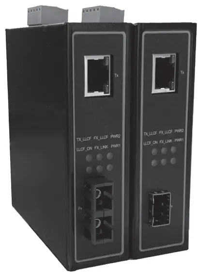
EF24L Series Industrial Ethernet to Fiber Media Converter
Industrial Ethernet to Fiber Media Converter
EF24L Series
Version 1.0
Updated in May, 2022
Installation Overview
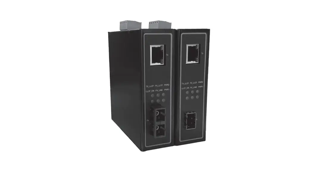
The device’s appearance is as in the figure below.
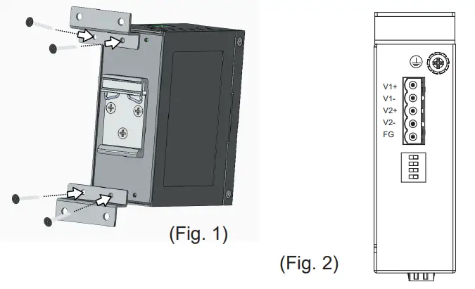
- If you have purchased the wall mount kit. proceed to place the screws on the back of the device as shown in (Fig. 1).
- Although internal grounding has been done inside. in order to ensure overall maximum performance and protect your device. it is still strongly advised to ground the device proper-ly: hazardous ESD can come into contact and damage your equipment. On the power terminal block. there is a terminal for Frame Ground. you can choose whether to connect it to the grounding or you may opt to connect to the grounding screw next to the terminal block ( the one chosen should be connected at all times ) (Fig. 2)

- You can then choose whether to plug in the other peripheral ports at this point or do it later depending on the actual location of the device or level of comfort for performing such operation.
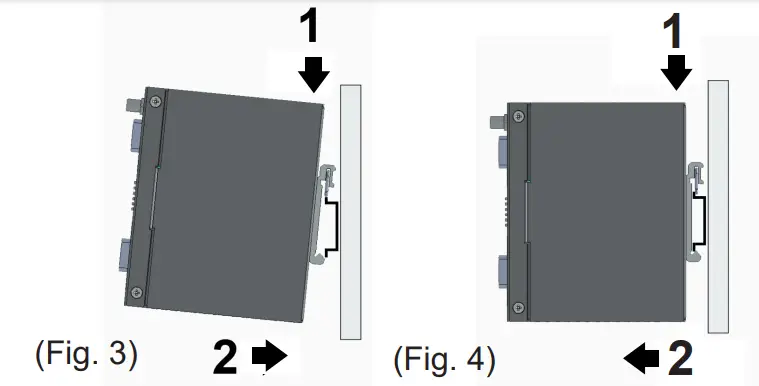
- Once the plate has been firmly put in place. proceed to mount the whole device as shown in (Fig. 3).Proceed to (Fig. 4) if you want to remove the device from DIN-Rail.

- ext, connect the device to the LAN (switch or PC. depending on the case). taking care on using the RJ-45 connector: after this. proceed to the device’s settings.
■ The openings to the sides are for the device’s heat dissipation. never obstruct or cover them with any objects or try to insert any objects through them.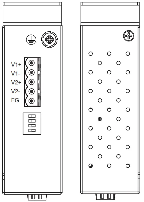
Package Check List
Inside the package you will find the following items:
- Industrial Ethernet to Fiber Media Converter x 1
- 5-Pin 5.08mm Lockable Terminal Block (Already mounted to the device) x 1
- DIN-Rail Kit (Already mounted to the device) x 1
- Installation Guide with Warranty Card x 1
Never install or work on electricity or cabling during periods of lightning activity. Never connect or disconnect power when hazardous gases are present.
Caution: CLASS 1 LASER PRODUCT. Do not stare into the laser!
Warning: Hot Surface. Do Not Touch. RESTRICTED ACCESS AREA: The equipment should only be installed in a Restricted Access Area.
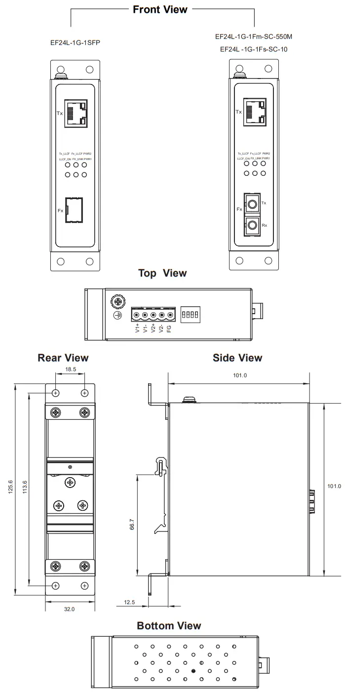
Product Layout
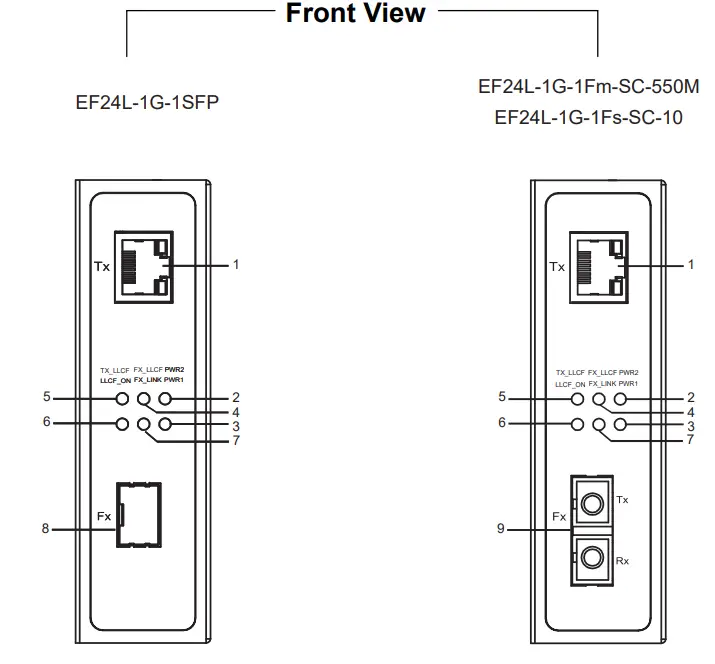
- 10/100/1000 Base-T(X) RJ-45 Pod
- PWR2 LED
- PWR1 LED
- Fx_LLCF LED
- Tx_LLCF LED
- LLCF_ON LED
- Fx_Link LED
- 100 Base-FX a 1000 Base-X SFP Slots
- 100/1000 Base-X SC connector
Top View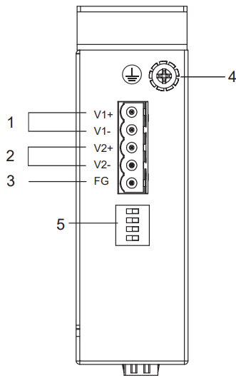
- Terminal for PWR1
- Terminal for PWR2
- Frame Ground
- Grounding Screw
- Dip Switch
100 Base-FX or 1000 Base-X Fiber Optics SFP Slot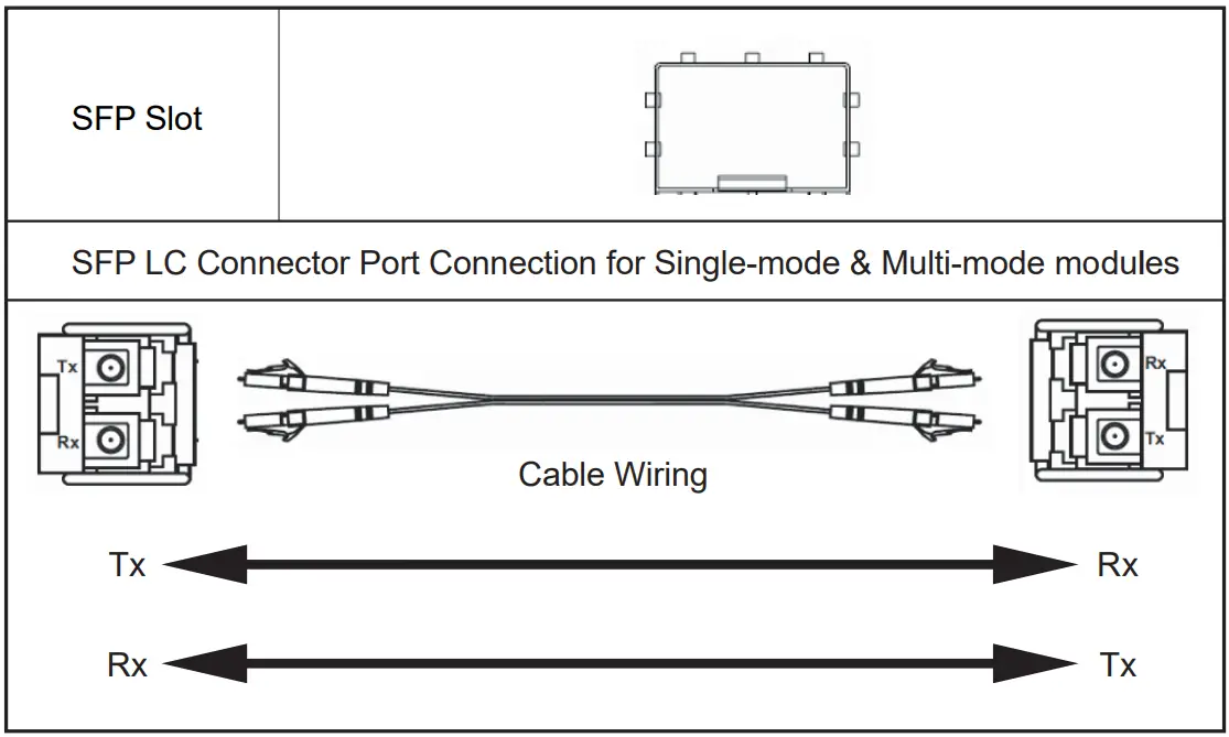 Caution
The SFP va. Shbold be ut.e0 h COreJobtlon wan a MSA combilatil OCTICal Iran:Chace
100/1000 Base-SX / LX Fiber Port
SC Pat al-medial for Multi-mode a Stgle-mode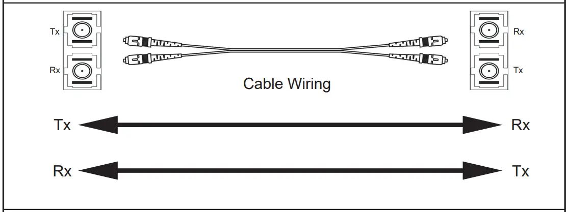 Cable Type
Multi-mode : 50/125pm or 62.5/125pm fiber patch cord cable
Single-mode : 9/125pm fiber patch cord cable
DIP Switch
| Pin | Mode | OFF | ON |
| 1 | Fiber Speed | 1000Base-X | 100Base-FX |
| 2 | Link Transparency | Disable | Enable |
| 3 | Fiber Auto Negotiation | Enable | Disable |
| 4 | Jumbo Frame (10KB) | Disable | Enable |
LED Indicators
| LED | Color | Status | Description |
| PWR1 PWR2 | Green | ON | Power is being supplied through this power input |
| OFF | Power is not supplied through this power input | ||
| LLCF_ON | Green | ON | The link transparency is enabled |
| OFF | The link transparency is disabled | ||
| Fx_Link | Green | ON | The link is connected and no traffic is detected |
| OFF | The link is disconnected | ||
| Blinking | Data is transmitting or receiving | ||
| Fx_LLCF | Red | ON | The Fiber port is forced to link down by LLCF |
| OFF | The Fiber port is not forced to link down by LLCF | ||
| Tx_LLCF | Red | ON | The Copper port is forced to link down by LLCF |
| OFF | The Copper port is not forced to link down by LLCF | ||
| Tx_Link/Act | Green | ON | The link is connected. |
| OFF | The link is not connected. | ||
| Blinking | Data is transmitting or receiving | ||
| Tx_Speed | Bi-color | Orange | The link is connected at 100Mbps |
| Green | The link is connected at 1Gbps | ||
| Off | The link is connected at 10Mbps |
Dimensions and Layout (unit=mm)
 o The wall mount kit Illustrated in this document is for reference coy and is not included in the package.
Field Maintenance and Service
- If the device requires servicing of any kind, you may need to disconnect and remove it from its mounting. The initial installation should be done in a way that makes this as convenient as possible.
- Voltage/Power lines should be properly insulated as well as other cables. Be careful when handing to avoid tripping over them.
- Do not under any circumstance insert foreign objects of any kind into the heat dissipation holes located on the different faces of the device. This may not only harm the internal layout but might cause harm to you as well.
- Don not under any circumstance open the device for any reason. Please contact your dealer for any repair needed or follow the instructions on your User’s Manual.
Warranty Policy
Warranty Conditions
Products supplied by ATOP Technologies are covered in this warranty for sub-standard performance or defective workmanship. The warranty is not, however, extended to goods damaged in the following circumstances: (a) Excessive forces or impacts (b) War or an Act of God: wind storm, fire, flood, electric shock.earthquake (c) Use of unqualified power supply, connectors, or unauthorized parts/kits (d) Replacement with unauthorized parts
RMA and Shipping Costs Reimbursement
Customers shall always obtain an authorized eRMA- number from ATOP before shipping the goods to be repaired to ATOP. When in normal use. a sold product shall be replaced with a new one within 3 months after purchase. The shipping cost from the customer to ATOP will be reimbursed by ATOP. After 3 months and still within the warranty period, it is up to ATOP whether to replace the unit with a new one; normally, as long as a product is under warranty, all parts and labor are free of charge to the customers.
After the warranty period, the customer shall cover the cost for parts and labor.Three months after purchase, the shipping cost from the customer to ATOP will not be reimbursed, but the shipping cost from Atop to the customer will be paid by ATOP.
Limited Liability
ATOP shall not be held responsible for any consequential losses from using ATOP’s product.
Warranty Period
| Product Categories | Warranty |
| Ethernet Switches | 5 Years |
| Wireless | |
| Serial Device Servers | |
| Modbus Gateways | |
| Embedded Device Servers | |
| Media Converters | |
| DIN-Rail Power Supplies | 3 Years |
| Power Adaptors | 1 Year |
| Antennas | |
| Other Accessories |
The warranty certification will not be effective without an authorized stamp issued by ATOP’s overseas agents.
Purchase Date: / (yyyy/mm/dd)
Serial Number………………………… ATOP Customer Services and Supports
- Please contact your local dealers or ATOP Technical Support Center at the following numbers. + 886-3-550-8137 (ATOP Taiwan)
- Please report the defected problems via ATOP’s
Web site or E-mail account
Web Site : www.atoponline.com.
E-mail : [email protected]
— Any changes to this material will be announced on ATOP website. —
![]() Tel: 886-3-5508137
Tel: 886-3-5508137
Fax: 886-3-5508131
www.atoponline.com
P/N: 2490000038


