DAN DRYER 4000 Loki Hand Dryer User Manual
IMPORTANT!
This product falls within the scope of the WEEE directive on recycling and recovery of waste electrical and electronic equipment.
- This product should not be disposed of with general household waste.
- This product must be reused if possible.
- Contact your local authority for further details.
- This product may also be returned to the manufacturer/retailer for proper treatment, recovery, and recycling.

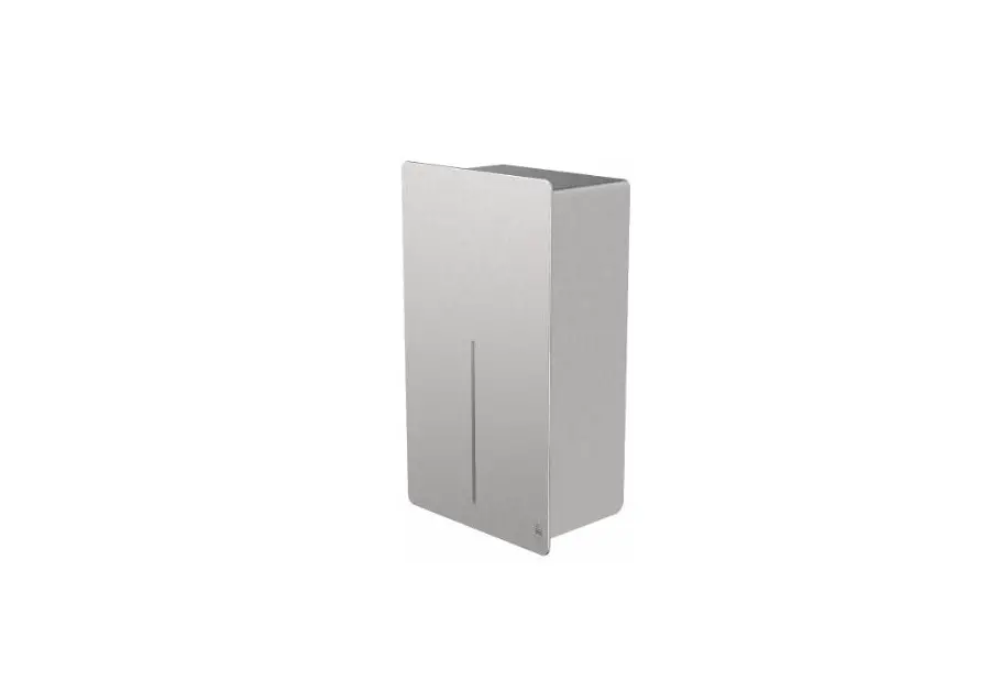
DIMENSIONS AND TECHNICAL SPECIFICATIONS
Dimensions

TECHNICAL SPECIFICATIONS
DESCRIPTION | DATA |
| Operating voltage | 110V-120V, 50/60Hz, 0.84-1.0kW 220V-240V, 50/60Hz, 0.84-1.0kW |
| Air temperature | 55°C — ambient temperature 25°C |
| lir speed | 95-115 m/s (adjustable) |
| ikkaotor type | 325-500W (adjustable) coal brush, 22000-29000 rpm. |
| Motor thermal protection | Auto resetting, thermostate turns off at: 120V at 135°C 240V at 95°C |
| Heating element | 325 – 500W (adjustable) |
| Heating element protection | Auto resetting, thermostate turns circuit off at: 85°C, thermal fuse turns off at 142°C |
| Drying time | 510-15 seconds |
| Stand-by power | 0.3-0.4W |
| Sensor type | Infrared, self adjusting |
| Sensor range | 110-230 mm adjustable. Standard 170mmt 20mm |
| Protection timer | 60 seconds auto shut off |
| IPClass | IP24 |
| Insulation class | Class 1 |
| Net weight | 5 kg |
| Gross weight | 5.7 kg |
- 4000 / 4001 Stainless steel, brushed, LOKI hand dryer, 230V/110V
- 4002 / 4003 White powder coated stainless steel, LOKI hand dryer, 230V/110V
- 4004 / 4005 Black powder coated stainless steel, LOKI hand dryer, 230V/110V
- 4006 / 4007 Custom RAL colour, stainless steel, LOKI hand dryer, 230V/110V
GENERAL SAFETY INFORMATION
![]() WARNING:
WARNING:
- All units must be equipped with a 3-wire service. Connect the ground wire according to the instructions.
- This product must be installed only by qualified persons. Use 2.0mm
- Turn off the power to the unit before servicing or cleaning. All wires must be disconnected.
- Incorrect installation, defect power cords, or failure to properly ground unit could result in electrical shock or life-threatening injuries.
We do not recommend to install this product less than 300 mm above washbasin, tabletop or other surface. This product is suitable for indoor use only.
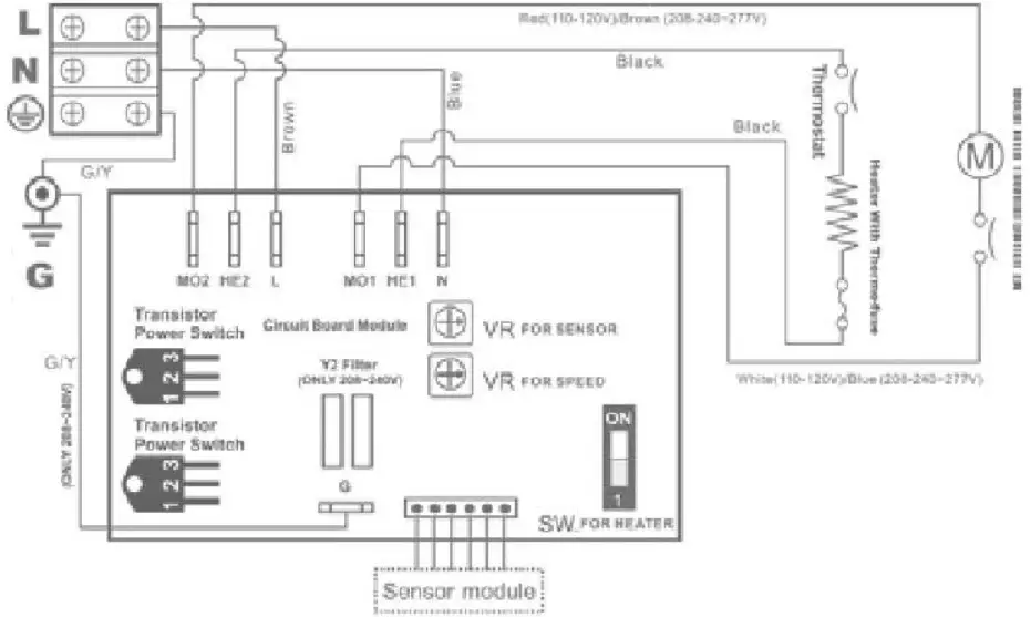
CIRCUIT DIAGRAM
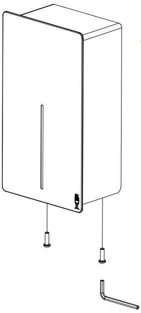
INSTALLATION
- Make sure the main breaker is turned off. Installation must be carried out by a qualified person in accordance with standards applicable in the country where the equipment is to be installed.
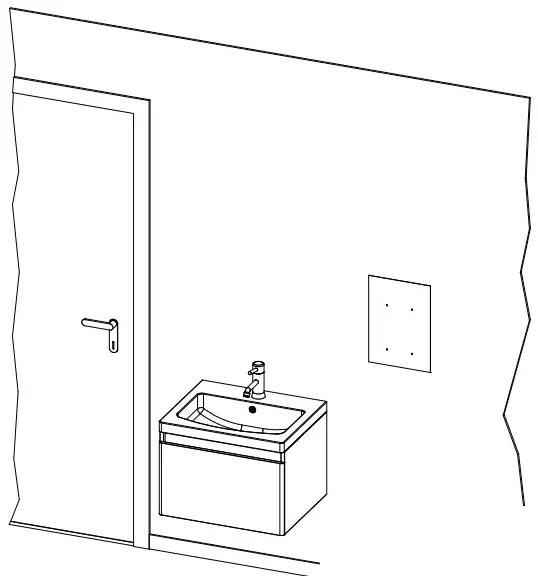
- Place template against the wall at desired height (see mounting height recommendations) and mark location of (4) mounting holes and the wire service entry.
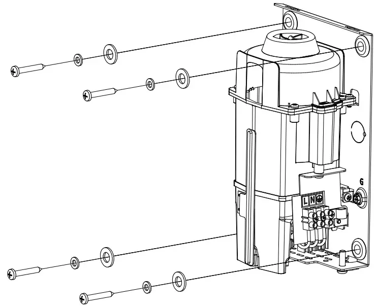
- Remove the two screws in the lower area of the unit and remove casing from its base.
- Place the template on the wall at the desired location. Drill (4) holes as indicated.
- Attach the base plate of the hand dryer to the wall with the screws supplied with the unit.
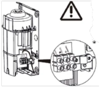
- Insert the power cord through the inlet hole. Fasten with the retaining clip.
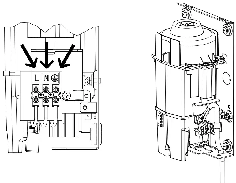
- Connect supply wires to terminal block.
Connections
- A. Connect live wire (coloured red, brown, or white) to the terminal block marked ”L”
- B. Connect neutral wire (coloured black or blue) to terminal block marked ”N”
- C. Connect the ground wire (coloured green or green and yellow) to the screw marked.
NOTE
Colours of live and neutral wires depend on voltage of supply service.
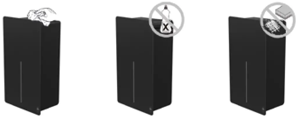
USER GUIDE
- No-touch operation.
- Shake excess water from hands.
- Place hands under the outlet to start operation.
- Rub hands lightly and rapidly.
- Stops automatically after hands are removed.
RECOMMENDED INSTALLATION HEIGHT
From bottom edge of hand dryer above finished floor.
| Men | 1270 mm (50″) | |
| Women | 1194 mm | (47″) |
| Children, 4-7 years | 889 mm | (35″) |
| Children, 8-10 years | 991 mm | (39″) |
| Children, 11-13 years | 1092 mm | (43″) |
| Children, 14-16 years | 1194 mm | (47″) |
| Wheelchair users | 1016 mm | (40″) |
CLEANING AND MAINTENANCE
Routine cleaning and maintenance is recommended every 12 months to ensure your hand dryer is running at optimal performance.
- Disconnect the electrical supply.
- Remove the two cover-mounting screws.
- Remove the cover.
- Clean the interior of the dryer and remove any dust.
- Do not soak.
- Use a damp cloth and mild cleaning solution. Never use cleaning detergents with an abrasive effect.
- Replace the cover. Do not overtighten the screws.
WARM AIR SPEED ADJUSTMENT
- Switch off the power and remove the cover.
- Use Phillips screwdriver or flat notch.
The air speed is adjusted on the VR potentiometer.
Clockwise to increase air speed(+).
Counterclockwise to decrease air speed(-).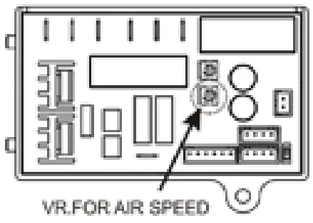
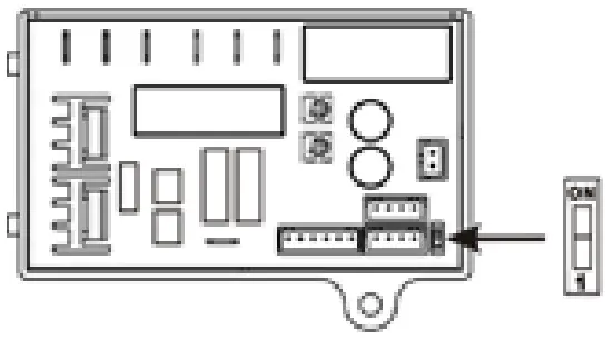
HEATING ELEMENT SWITCH
- Switch off the power and remove the cover.
- The heating element switch is located on the timer.
Adjust with a flat screwdriver: - Slide switch to ”ON” = heating element on.
- Slide switch to ”1” = heating element off.
SENSOR RANGE ADJUSTMENT
- The sensor range is adjustable between 100mm and 230mm. Standard range 130mm ± 20mm.
- Clockwise: To increase sensor activation range (+)
- Counterclockwise: To decrease sensor activation range (-)
- The sensor activation range should be adjusted to its environments, e.g. light and distance to the bottom of the sink.
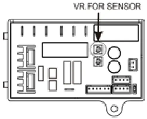
Note: Do not overturn the sensivity adjustment.
TROUBLESHOOTING AND CORRECTIVE ACTIONS
SYMPTOM | CORRECTIVE ACTION: FIRST-TIME INSTALLED HAND DRYERS |
| The dryer does not run | First ensure that the breaker supplying the dryer is operational. If it is, disconnect the power and remove the cover. Taking suitable precaution to avoid shock hazard, reconnect the power and check for voltage on the terminal block. Verify that connections are made correctly. |
| The dryer cycles by itself and runs constantly | Ensure that there is no obstruction on or in front of the IR sensor. Clean any dirt off the sensor lens. If problem persists, replace the sensor. |
| The dryer is very loud and does not run for a complete cycle | Ensure that the supply voltage is correct. The dryer will make a loud humming noise if the input voltage is too high. Verify voltage requirement on the unit rating label and correct accordingly. If PCB is damaged, replace unit as well as IR sensor. |
| The dryer runs, but the airspeed is low | Ensure that the supply voltage is correct. The dryer will run slowly if the input voltage is too low. Verify voltage requirement on the unit rating label and correct accordingly. |
SYMPTOM | CORRECTIVE ACTION: USED HAND DRYERS |
| The dryer does not run | First ensure that the breaker supplying the dryer is operational. If it is, disconnect the power and remove the cover Replace PCB and IR sensor. Taking suitable precaution to avoid shock hazard, reconnect the power and check for voltage on the terminal block. |
| The IR-sensor detects only close range objects | Ensure that there is no obstruction on or in front of the IR sensor. Clean any dirt off the sensor lens. If problem persists, disconnect the power and remove the cover. Taking suitable precaution to avoid shock hazard, reconnect the power and try carefully adjusting the sensitivity range (yellow slot in blue component on PCB). If problem persists, replace IR sensor. |
| The dryer gets hot. but there is no air stream | Disconnect the power. Remove the cover and disassemble the blower/fan unit. Replace motor. |
| The dryer blows only cold air during a full cycle | Disconnect the power. Remove the cover and disassemble the blower/fan unit. Test the thermostate for open circuit. Check the heating element for defects. Replace defect heating element. |
| The air pressure is low | Check the output nozzle for obstructions. If none, disconnect the power and remove the cover. Remove any dirt from the inlet. Disassemble the blower/fan unit, check if motor brushes are worn ( 10 mm graphite remains) and replace them, if necessary. |
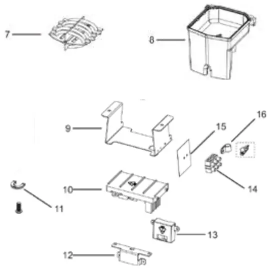
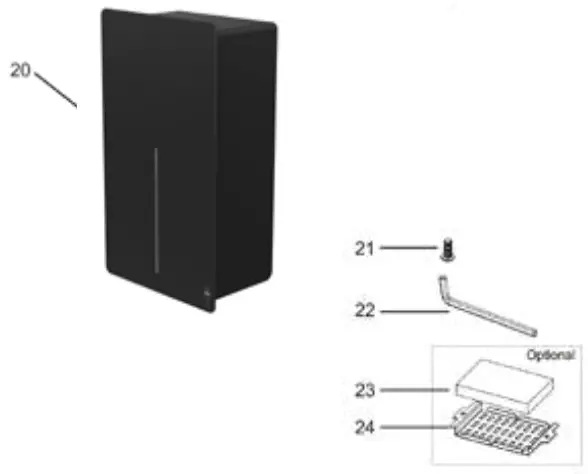
PARTS LIST
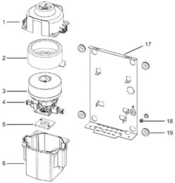
- Fan housing (top)
- Gasket (large) for fan housing
- Motor
- Motor carbon brush
- Gasket (small) for fan housing
- Fan housing (bottom)
- Heating element
- Outlet nozzle
- Outlet nozzle bracket
- Timer
- Cable protector
- Bracket for sensor
- Sensor
- Terminal block
- Insulation mylar shield with LNG mark
- Cable clamp
- Base plate
- Grounding screw with cup washer
- Rubber bushing (4 reqd.)
- Housing
- Housing screws (2 pcs.)
- Allen key for housing screws
- HEPA filter (optional)
- Bracket for HEPA filter (optional)
Support
DAN DRYER A/S
Alsikevej 8
DK – 8920 Randers NV
T: +45 8641 5711
E: [email protected]
W: dandryer.com


