
Specifications
- Product Dimensions
2.75 x 2 x 4.5 inches - Item Dimensions LxWxH
2.75 x 2 x 4.5 inches - Item Weight
0.35 Pounds - Style
Thermostat - Power Source
Electric - Controller Type
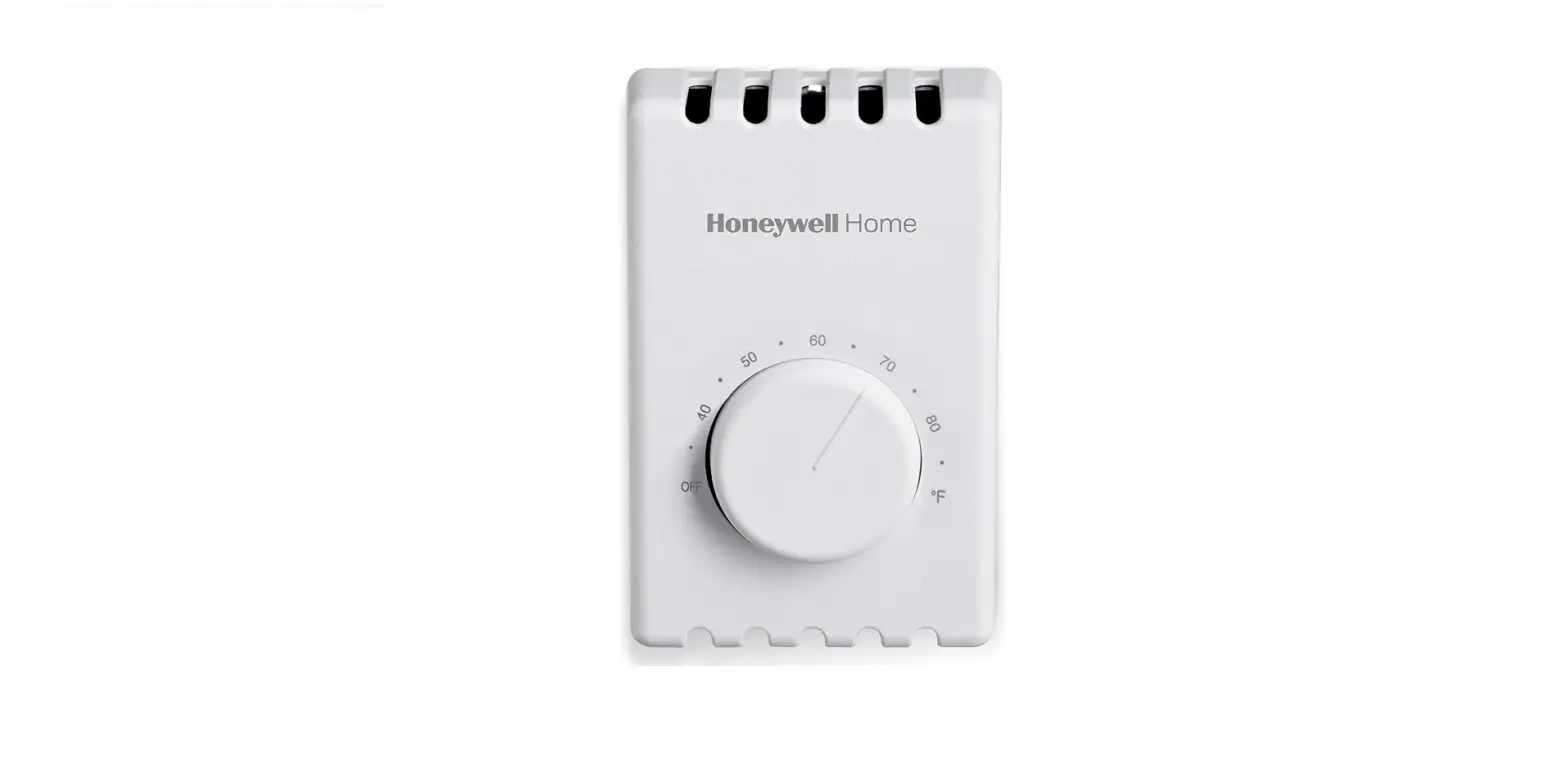
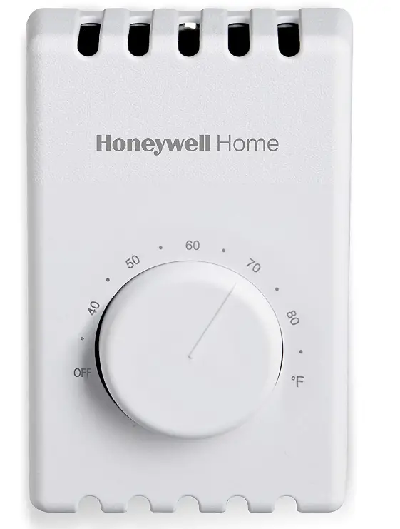
Mechanical knob - Voltage
120 Volts - Material
Plastic - Mounting Type
Wall Mount - Control Type
Dial - Shape
Rectangular - Type of Bulb
LED - Display Style
Manual - CT410A provides a single-line break.
- CT410B provides double-line breakópositive OFF
- Temperature Range
40°F to 80°F (4°C to 27°C) - Electrical Ratings
60 Hz noninductive; 22A at 120-240 Vac; 19A at 277 Vac - Brand
Honeywell Home
Introduction
The simple, worry-free operation of the Honeywell Home manual electric baseboard thermostat works on 4-wire (double pole) electric heat applications (baseboard or line volt). It is UL- and CSA listed for safety and has a simple dial-type mechanical control.
What’s In the Box?
- Thermostat
- Mounting Hardware
- Install Guide
APPLICATION
Your new Honeywell Electric Heating Thermostat provides line voltage control of radiant cable, electric baseboard, and resistive-rated fan forced heaters within the ratings listed below.
WARNING
Electrical Shock Hazard
This thermostat is a line voltage control (120ñ240 Volts). Do not install it if you are not completely familiar with house wiring. If handled improperly, there is a risk of electric shock hazard, which may cause serious injury or death.
INSTALLATION
When Installing This Product
- Read these instructions carefully. Failure to follow them could damage the product or cause a hazardous condition.
- Check the ratings given in these instructions to make sure the thermostat is suitable for your application.
- After installation is complete, check out the operation as provided in these instructions.
Preparation
- Proper installation of your Honeywell thermostat will occur if you follow these instructions STEP-BY-STEP. It is recommended that as you read, understand and complete each step, you check it off with a pencil or pen.
- Check thermostat suitability for your home system by reviewing the ratings above.
- Make certain that your heating system is working, especially if it has been inoperative for a length of time. If the system does not work, contact your local electrician for assistance.
- Carefully unpack your new thermostat. To avoid damage to the sensing element, do NOT remove the thermostat cover until the wiring has been completed.
- Save packages of screws, instructions, receipt, and proof-of-purchase.
Remove Old Thermostat
WARNING
Electrical Shock Hazard. Can cause severe injury, death, or property damage. Begin by turning off the power to the heating circuit at the main service panel.
- Remove the cover of old thermostatócover normally snaps off when pulled firmly from the bottom. If it resists, check for a screw that locks the cover.
- Loosen screws holding thermostat base to the outlet box and lift away.
- Disconnect wires from the old thermostat. As you disconnect each wire, tape the end and label it with the letter of the terminal designation to make reconnection to the new thermostat easier.
- Check the old insulation for cracks, nicks, or fraying, and apply high-quality plastic tape was necessary for adequate insulation.
- Retain the old thermostat for reference purposes and until your new thermostat is functioning moothly.
Wire and Mount New Thermostat
- Remove the thermostat cover by grasping the top and bottom ends with fingers, and pulling outward.
- Connect wires to the thermostat as shown in the applicable wiring diagram. Push the wires into the outlet box, and insert the thermostat into the box for mounting by pushing against top and bottom of the thermostat base.
IMPORTANT
Do not press on the setting knob. Rough handling or strong pressure can damage the knob or sensing element, and change the calibration.
- Secure the thermostat to the box with the two captive mounting screws provided.
- Replace the thermostat cover.
- Set knob to desired room temperature.
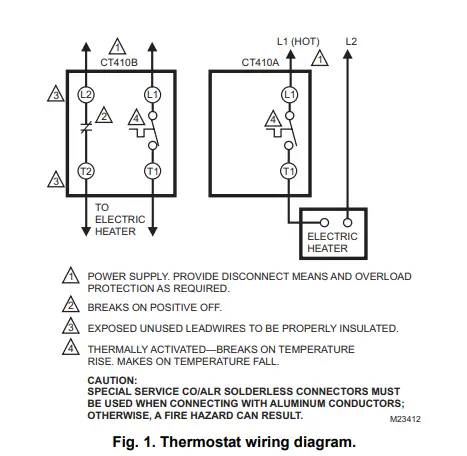
- POWER SUPPLY. PROVIDE DISCONNECT MEANS AND OVERLOAD PROTECTION AS REQUIRED.
- BREAKS ON POSITIVE OFF.
- EXPOSED UNUSED LEAD WIRES TO BE PROPERLY INSULATED. THERMALLY ACTIVATED—BREAKS ON TEMPERATURE RISE. MAKES ON TEMPERATURE FALL.
CAUTION
SPECIAL SERVICE CO/ALR SOLDERLESS CONNECTORS MUST BE USED WHEN CONNECTING WITH ALUMINUM CONDUCTORS; OTHERWISE, A FIRE HAZARD CAN RESULT.
Check Out Thermostat
- Turn on the power to the heating system.
- Turn the setting knob all the way clockwise; listen for clicking sound as the switch makes contact. Electric heater should begin operation.
- Turn the knob all the way counterclockwise; listen for clicking sound as the switch breaks contact. The electric heater should shut off.
Setting Thermostat
- Begin with setting the knob at 70°F (20°C) on the scale.
- If this setting is not satisfactory after at least two hours of operation, turn the setting knob up to raise the temperature, or down to lower the temperature. Move the knob only a degree each time
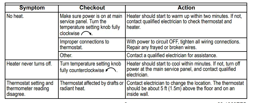
Troubleshooting
Your Honeywell thermostat requires little or no attention. Most problems can generally be traced to the following
1-YEAR LIMITED WARRANTY
Honeywell warrants this product to be free from defects in the workmanship or materials, under normal use and service, for a period of one (1) year from the date of purchase by the consumer. If at any time during the warranty period the product is determined to be defective or malfunctions, Honeywell shall repair or replace it (at Honeywell’s option).
If the product is defective
- Return it, with a bill of sale or other dated proof of purchase, to the place from which you purchased it; or
- Call Honeywell Customer Care at 1-800-468-1502. Customer Care will make the determination whether the product should be returned to the following address: Honeywell Return Goods, Dock 4 MN10-3860, 1885 Douglas Dr. N., Golden Valley, MN 55422, or whether a replacement product can be sent to you.
This warranty does not cover removal or reinstallation costs. This warranty shall not apply if it is shown by Honeywell that the defect or malfunction was caused by damage that occurred while the product was in the possession of a consumer.
Honeywell’s sole responsibility shall be to repair or replace the product within the terms stated above. HONEYWELL SHALL NOT BE LIABLE FOR ANY LOSS OR DAMAGE OF ANY KIND, INCLUDING ANY INCIDENTAL OR CONSEQUENTIAL DAMAGES RESULTING, DIRECTLY OR INDIRECTLY, FROM ANY BREACH OF ANY WARRANTY, EXPRESS OR IMPLIED, OR ANY OTHER FAILURE OF THIS PRODUCT. Some states do not allow the exclusion or limitation of incidental or consequential damages, so this limitation may not apply to you.
THIS WARRANTY IS THE ONLY EXPRESS WARRANTY HONEYWELL MAKES ON THIS PRODUCT. THE DURATION OF ANY IMPLIED WARRANTIES, INCLUDING THE WARRANTIES OF MERCHANTABILITY AND FITNESS FOR A PARTICULAR PURPOSE, IS HEREBY LIMITED TO THE ONE-YEAR DURATION OF THIS WARRANTY. Some states do not allow limitations on how long an implied warranty lasts, so the above limitation may not apply to you.
This warranty gives you specific legal rights, and you may have other rights which vary from state to state. If you have warranty questions, please write Honeywell Customer Relations, 1985 Douglas Dr., Golden Valley, MN 55422 or call 1-800-468-1502. In Canada, write Retail Products ON15-02H, Honeywell Limited/Honeywell LimitÈe, 35 Dynamic Drive, Toronto, Ontario M1V 4Z9.
Automation and Control Solutions
Honeywell International Inc. Honeywell Limited-Honeywell LimitÈe
1985 Douglas Drive North 35 Dynamic Drive
Golden Valley, MN 55422 Toronto, Ontario M1V 4Z9
Frequently Asked Questions
Yes, 2 poles so you can switch both sides of a 220-volt circuit. Or you can use just 1 pole.
It’s a line-voltage thermostat. Typically it would take the place of a wall switch to control a switched plug. If you are looking for something to replace a 24 VAC furnace thermostat, this is not it.
4 1/2″ tall and 2 7/8″ wide. Depth is 1 1/2″ outside of the box (measured from the lip of the box. I used a full-depth box but can’t tell how deep the switch extends into the box without taking it apart.
These can be calibrated. I have six of these to control 240V baseboard heaters. First, set them to the temperature that you want the room to be and let the temperature of the room stabilize for several hours. Note where on the dial where the pointer should be. Remove the cover, and then carefully remove the knob without disturbing its position. It snaps off. Then, place the knob back on so it points to the temperature of the room and push it so it snaps on. Replace the cover. If the control was turned when pushing the knob back on, remove it again and correct its position. I have done this with all six of my thermostats and they are all accurate now.
We have radiant ceiling heat and I have gradually been replacing the original 1970s thermostats with this model and it works fine.
The thermostat has 4 wires. Look at the instructions and connect the black and white coming from the breaker box to 2 wires marked supply and the other 2 wires on the thermostat get connected to 2 wires marked as Load. Connect 2 ground (bare) wires together.
My thermostat is only controlling the heat lamp so overload problems.
I haven’t personally used one of these with a SunTouch Mat but it should work, provided: 1) your intent is for the floor mat heater to warm the entire room to the temperature set by the Honeywell Thermostat, and 2) the Suntouch Mat power usage is rated lower than the 5280 Watts max this thermostat is rated for. This thermostat has wires for 120 Volt or 240-volt usage, so you would just hook up the 120 sides if using with a 120V mat.
Hi there. Thank you for reaching out to us. Per the installation guide, the Honeywell Manual 4 Wire Premium Baseboard/Line Volt Thermostat is only recommended for 120, 240, and 227 vac baseboard systems.
Yes, you can use sheet metal screws to mount it onto the baseboard itself. Note, that it will not be accurate due to the proximity.
It depends on the model. There should have been informed in the box or you can call Honeywell. If it’s done wrong the first time it will burn up the unit and you may as well forget it. Please call a certified electrician. I know it may cost $75 (No one should charge more than that) for that job, and then he/she is liable b/c if you mix up things you may burn your house down or harm yourself.
Yes, it will work with 120 v or 220v.
The thermostat is hooked up with a 12-2 with ground cable. The black and white from the 12-2 are hooked to the thermostat feed while the bare copper is neutral.
You need to find the wattage ratings on each of those heaters, add them up, and if the total is under 5280 then this device can handle it. However, you should also make sure that your wiring and circuit breaker can handle that kind of load. You have about 4320 watts to work with on your average 240v 20 Amp 12 gauge circuit. On a 240v, 30 Amp, 10 gauge circuit you have about 6480 watts to work with. Do not exceed these wattages or you risk fire.
Turn the dial to the left to turn it off. now slowly turn it to the right and listen for a click DO Not LOOK AT THE TEMPERATURE after you hear the click wait about a minute now go to your heater that you turned on and you should feel the heat now look at the temperature on the thermostat that is where your heater will come on if you turned it and it clicked at 75. And you want it to come on at 70 that is how far off your calibration is off.
Since this unit is wired for 240 volts it has 2 separate circuits out of the control side which would let you control each one on its own if you are using it that way. If you are only using a single pole 30a 120v circuit you would need to check the amperage of each of the heaters to see if the 30a circuit would run both heaters. As far as this unit controlling both I think it would be able to control them with no problem.
There is no LED indicator light on this thermostat.
This is to control electric heat or blowers that run on 110 or 220 VAC nominal voltage. Most baseboard hot water-based systems use the generic all-purpose type thermostats you can purchase to turn on and off your furnace.


 39444/ Zw4103 Manual")


 39337 / Zw4103 Manual")


