![]() SY-01B Electric Syringe Pump
SY-01B Electric Syringe Pump
User Manual
Key Components for Analytical Instrument
Ecological Close-loop Supplier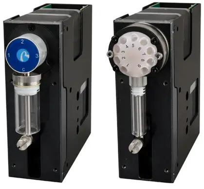
Chapter 1 Product Introduction
1.1 SY-01B Features at-a-Glance
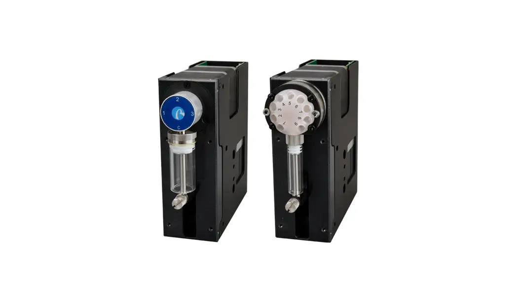
Smart SY-01B syringe pump is the latest member of the high precision micro syringe pump series developed by Nanjing Runze Fluid Control Equipment Co., LTD. A variety of distribution valves and syringes are provided to meet the needs of most users for high-precision liquid handling. Multiple pumps can be used together in series. The excellent performance of Smart SY-01B syringe pump guarantees the development and application of users and achieves the desired purpose.
1.2 Naming Rules
Model parameters are as follows:
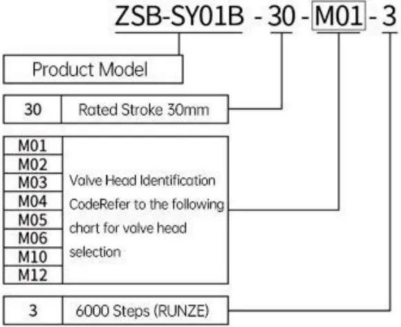 Example: Syringe pump with M03 valve, 6000 control steps is named: ZSB-SY01B-30-M03-3
SY-01B Syringe Options (Syringe Stroke: 30mm).
 | Specification | ||||
| 25ul | 50ul | 125ul | 250ul | 500µl | |
| 1.25ml | 2.5ml | 5ml | |||
1.3 Valve Head Configuration
 | Valve Model:M01 Fluid Logic:Y Flow Path (C-1 /1-2 /C-2 interlinked) Wetted Material: PCTFE/ Sapphire |
 | Valve Model:M02 Fluid Logic: T Flow Path (C-1-2 /C-1 /1-2 d /C-2 Wetted Material: PCTFE/ Sapphire |
 | Valve Model:M03 Fluid Logic:Distribution Flow (C-1 /C-2 /C-3) Wetted Material: PCTFE/ Sapphire |
 | Valve Model:M04 Fluid Logic:Radio Flow Path (C-1/1-2/2-3/C-3) Wetted Material: PCTFE/ Sapphire |
 | Valve Model: M05 Fluid Logic: Bi-pass Flow Path (C-1/2-3/C-3/1-2 interlinked) Wetted Material: PCTFE/ Sapphire |
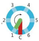 | Valve Model: M06 Fluid Logic: Distribution Flow Path (C selectively link to port 1-6) Wetted Material: PCTFE/Sapphire |
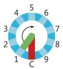 | Valve Model: M10 Fluid Logic: Distribution Flow Path (C selectively link to port 1-9) Wetted Material: PCTFE/Sapphire |
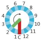 | Valve Model: M12 Fluid Logic: Distribution Flow Path (C selectively link to port 1-12) Wetted Material: PCTFE/Sapphire |
1.4 Calculation of the Injection Accuracy & Injection Volume
Example 1: Take the single-step accuracy (resolution) of a 5ml syringe (stroke 30mm) as an example,
5ml=5000µl
30mm=6000 steps
5000µl÷6000 steps=0.8333µl/step
(Note): One step of the syringe pump corresponds to a capacity of 0.8333µ L/step, which is the minimum resolution of a 5ml syringe.
Example 2: Syringe pump needs to aspirate or dispense liquid 3.8ml, and the corresponding calculation should be as follows:
3.8ml=3800µl
3800µl÷0.8333µl/step=4560 steps(rounding off)
It is found that the parameters to be executed for the syringe pump for a 3.8ml volume of liquid is 4560 steps (11D0 in hexadecimal).
(Note): The preceding calculations are all in decimal notation. When you use debugging tools or write code, the parameter input should be in hexadecimal notation.
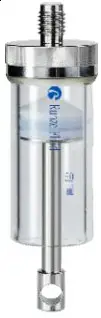
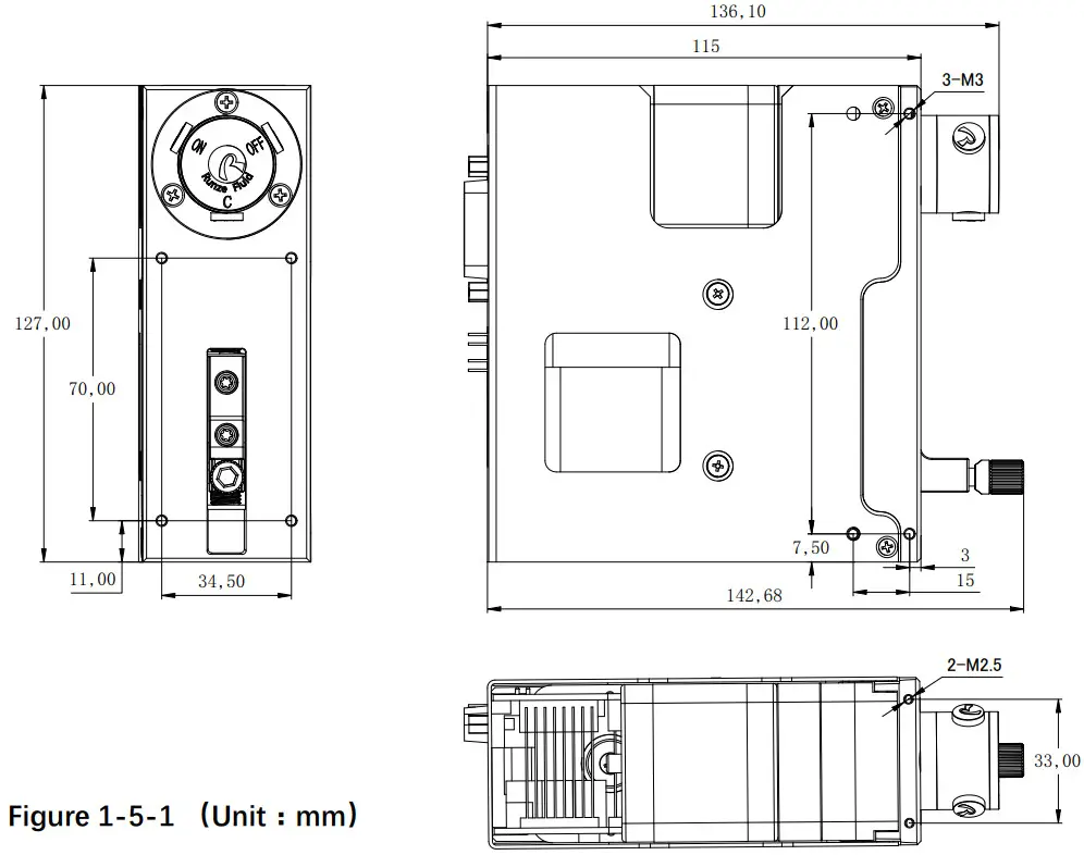
1.5 Syringe Pump Structure and Installation of Syringe
- The external dimensions and mounting hole dimensions are as follows

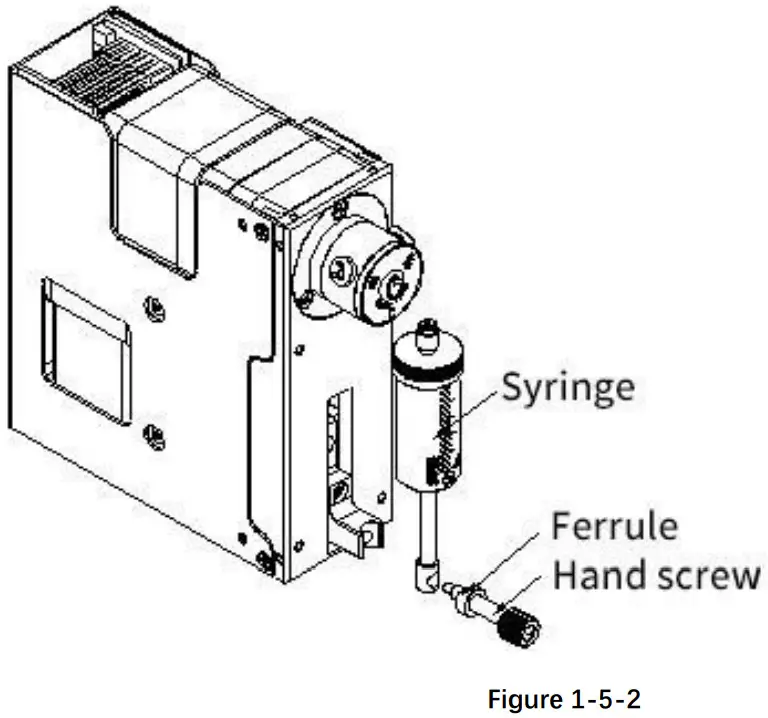
- The disassembly diagram of syringe is as follows:
 Note: When disassembling, the push rod should be run to the bottom dead point, then loosen the hand screw and take it out together with the ferrule, and unscrew the syringe in CCW rotation,
 - Installation diagram of syringe is as follows:

 Note: When disassembling, the push rod should be run to the bottom dead point, then loosen the hand screw and take it out together with the ferrule, and unscrew the syringe in CCW rotation,
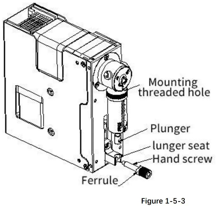
Note: When installing the syringe, align the syringe thread with the mounting hole and tighten it clockwise, then push the plunger to the plunger seat. Align the center of the hole, insert the hand screw with the ferrule, and then tighten the hand screw.
1.6 Device Port Definition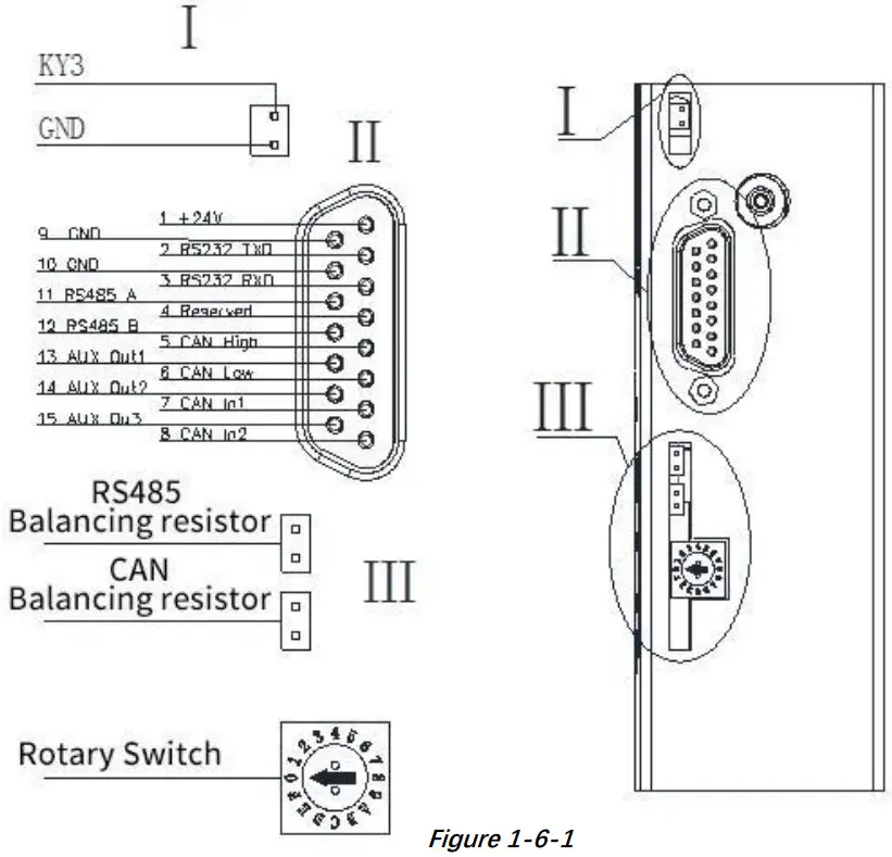 1.6.1 Wiring Diagram
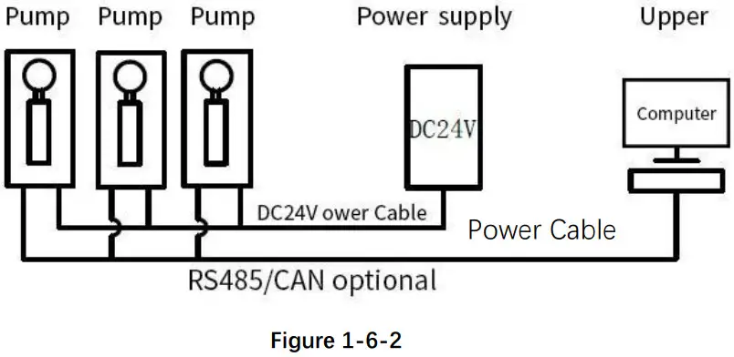
- Multiple parallel control wiring diagram
 Note
Note
1. In this case, multiple devices communication needs to change the address of each device.
2. Please use the rated power supply correctly. If the laboratory linear power supply is used, please adjust the protection current above the rated current of the device.
3. When RS485 and CAN are used in parallel, short connects the jumper caps of RS485 or CAN in figure 2-2 to ensure normal communication
4. The default address of the communication device is 00 and the baud rate is 9600.
5. It is recommended that no more than 20 devices are used in parallel to ensure the stability of communication, or add a communication amplifier to strengthen the communication capacity to ensure normal communication. - Single control wiring diagram
 Note: 1. In this case, the default address of a single device communication is 00 and the baud rate is 9600.
2. Please use the rated power supply correctly. If the laboratory linear power supply is used, adjust the protection current above the rated current of the device - The wiring of the equipment accessories is described as follows
 Note: 1. When connecting DC24V power supply, ensure that the switching power supply is connected when the power is off. Do not reverse the polarity.
2. When connecting the communication line, ensure that the 24V power supply is off. Live connection of communication lines may burn the processor.
3. The syringe pump can only use one of the three communication modes when working. Do not use the three communication modes at the same time. The communication lines that are not in use can be cut or rolled up.
 Note
Note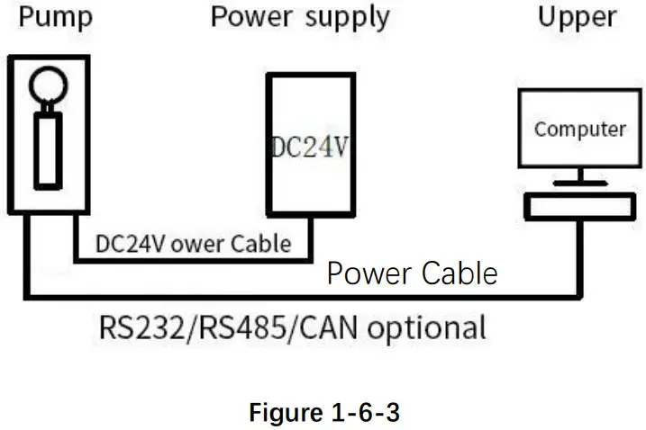 Note: 1. In this case, the default address of a single device communication is 00 and the baud rate is 9600.
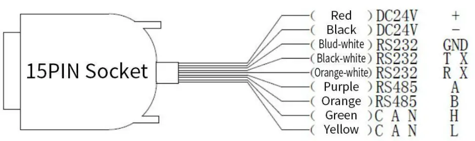 Note: 1. When connecting DC24V power supply, ensure that the switching power supply is connected when the power is off. Do not reverse the polarity.
1.7 Technical Parameters
| Items | Parameter |
| Accuracy | ≤1%@100% Rated stroke |
| Precision (Repeatability) | 0.3%-0.5%@100% stroke |
| Rated Stroke | 30mm(6000 steps) |
| Maximum Speed | 450rpm |
| Linear Speed | 0.0125 mm/s-3.75mm/s |
| Running Time (per rated stroke) | 8s-2400s |
| Resolution /Minimum Injection Accuracy | 0.005mm/per step |
| Transmission Structure | Trapezoidal screw(Lead 1mm/2mm) |
| Syringe Configuration | 25μl、50μl、125μl、250μl、500μl、1.25ml、2.5ml、5ml |
| Valve Model(available) | M01、M02、M03、M04、M05、M06、M10、M12 |
| Wetted Material | Borosilicate glass, PCTFE valve head, Sapphire rotor/stator、PTFE |
| Max. Pressure Rating | / |
| Tube Connection | 1/4-28UNF female thread |
| Syringe Connection | 1/4-28UNF female thread |
| Communication Interface | RS232/RS485/CAN bus |
| Communication Rate | RS232/485 bus:9600bps、19200bps、38400bps、57600bps、115200bps CAN bus:100kbps、200kbps、500kbps、1Mpbs |
| Device Address and Parameter Settings | Communication Interface |
| Power Supply | DC24V/3A |
| Operating temperature | 5℃-55℃ |
| Operating humidity | <80% relative humidity, non-condensing |
| Dimension (L*W*H) | 142.7*127*45 |
| Net Weight | 1.5kg |
Chapter 2 Syringe Pump Control Code Instruction
2.1 Overview
The data transmission between the syringe pump and the host computer (computer, single chip microcomputer, PLC, etc.) adopts serial communication (RS232, RS485, CAN bus). The following describes the communication format: the communication adopts asynchronous serial communication, the command and data frame adopt sum check, and the sum check is two bytes (2 Byte). Commands and data in communication are in hexadecimal format, shown as 0x00~0xFF or 0x0000~0xFFFF, and the parameters are stored in little-endian mode.
Communication Interface: RS-232, RS-485, CAN bus;
Communication Mode: two-way asynchronous, master-slave mode;
RS232/RS485 Baud Rate: 9600bps, 19200bps, 38400bps, 57600bps, 115200bps;
CAN Baud Rate: 100Kbps, 200Kbps, 500Kbps, 1Mbps;
Data Bits: 8 bits;
Parity: No parity check.
2.2 Installation and Debugging
- Install the debugging tools, see 《Instructions for Debugging Tools》for details
- Instructions for use, see 《SY-01B Quick Use Guide》for details.
2.3 Command Format Instruction
2.3.1 Control Command Format
a: Pump & Valve Parameter Setting Command (Factory Command)
B: Pump & Valve Parameter Query Command (Common Command)
C: Pump & Valve Action Command (Common Command)
Table 2-3-1 Send Command (Common Command)
Description of 0xXX: 0x means hexadecimal, and XX is a hexadecimal number with two digits. The input values in the tool software are all XX. The message frame of “Send Command” message is eight bytes, and the complete format is as follows:
| FH (frame header) | Address code | Function code | Status parameters | EOF (end of frame) | CUCUM (cumulative sum) | ||
| B0 | B1 | B2 | B3 | B4 | B5 | B6 | B7 |
| STX | ADDR | FUNC | Bit 1-8 | Bit 9-16 | ETX | Low byte | High byte |
| The 1st byte STX | Frame header (0xCC) |
| The 2nd byte ADDR : | Slave address(0x00~0xFF) Multicast address (0x80~0xFE) Broadcast address (0xFF) |
| The 3rd byte FUNC | Function code |
| The 4th , 5th byte | Parameters corresponding to the function code |
| The 6th byte ETX | End of frame(0xDD) |
| The 7th , 8 byte | Cumulative sum check code from byte 1 to 6 |
Table 2-3-2 Send Command (Factory Command)
| FH (frame header) | Address code | Function code | Code | EOF (end of frame) | Sum check | |||||
| B0 | B1 | B2 | B3, B4, B5, B6 | B7 | B8 | B9 | B10 | B11 | B12 | B13 |
| STX | ADDR | FUNC | PWD | Bit 1-8 | Bit 9-16 | Bit 17-24 | Bit 25-32 | ETX | Low byte | High byte |
Table 2-3-2 Respond Command
| FH (frame header) | Address code | Function code | Parameter | EOF (end of frame) | Sum check | ||
| B0 | B1 | B2 | B3 | B4 | B5 | B6 | B7 |
| STX | ADDR | STATUS | Bit 1-8 | Bit 9-16 | ETX | Low byte | High byte |
Note: The format of the send command and response command of the common command is the same, and all response command message frames are eight bytes.
2.3.2 Command Format Description
Definition of frame header and end of frame BO,B5(B11)
| Name | Code | Remarks |
| Frame header B0 | 0xCC | |
| End of frame B5 (B11) | 0xDD |
Note: The sending command and response command of the common command are the same. The header and the end of packet are B0 and B5 respectively. In particular, the end of the factory command is B11.
Description of Address code bit B1:
| Name | Abbreviation | Code B1 | Remarks |
| Address bit | Address | 0xXX |
Note: 1. Sending command is the same as responding command
2. XX in “0xXX” indicates that the value can be set. The default value is 0x00. The parameter value range is 0x00~0x7F
Table 2-3-4 Control Code Description(B2~B10)
a: Pump & Valve Parameter Setting Command (Factory Command) (B2~B10)
| Code B2 | Abbreviation | Code B3 B4 B5 B6 | Parameter Description B7 B8 B9 B10 |
| 0x00 | Set device address | B3=0xFF B4=0xEE B5=0xBB B6=0xAA | B7=0xXX (B8=0x00 B9=0x00 B10=0x00) where the value range of XX is 00~ 7F, the default value is 00 |
| 0x01 | Set RS232 baud rate | There are five baud rates: the factory default is 9600bps (B8=0x00 B9=0x00 B10=0x00) The baud rate corresponds to B7=0x00 is 9600bps The baud rate corresponds to B7=0x01 is 19200bps The baud rate corresponds to B7=0x02 is 38400bps The baud rate corresponds to B7=0x03 is 57600bps The baud rate corresponds to B7=0x04 is 115200bps | |
| 0x02 | Set RS485 baud rate | ||
| 0x03 | Set CAN baud rate | There are four baud rates: the factory default is 100K (B8=0x00 B9=0x00 B10=0x00) The baud rate corresponds to B7=0x00 is 100Kbps The baud rate corresponds to B7=0x01 is 200Kbps The baud rate corresponds to B7=0x02 is 500Kbps The baud rate corresponds to B7=0x03 is 1Mbps | |
| 0x10 | Set CAN destination address | B7=0xXX (B8=0x00 B9=0x00 B10=0x00) Where the value range of XX is 0x 00 to 0xFF, and the default value is 00 | |
| 0x50 | Set the address of multicast channel 1 | B7=0xXX (B8=0x00 B9=0x00 B10=0x00) Where the value range of XX is 0x80 to 0xFE, and the default value is 00 | |
| 0x51 | Set the address of multicast channel 2 | B7=0xXX (B8=0x00 B9=0x00 B10=0x00) Where the value range of XX is 0x80 to 0xFE, and the default value is 00 | |
| 0x52 | Set the address of multicast channel 3 | B7=0xXX (B8=0x00 B9=0x00 B10=0x00) Where the value range of XX is 0x80 to 0xFE, and the default value is 00 |
| 0x53 | Set the address of multicast channel 4 | B7=0xXX (B8=0x00 B9=0x00 B10=0x00) Where the value range of XX is 0x80 to 0xFE, and the default value is 00 | |
| 0xFC | Parameter Lock | All parameters are 0x00 | |
| 0xFF | Restore factory setting | All parameters are 0x00 |
For example: Use the 0x50/51/52/53 command to set the multicast address (this example only uses the 0x50/51/52 three commands)
Use three RUNZE SY01B syringe pumps with the same software version. In RS485 communication mode, set their addresses into 00, 01, 02 and make a mark. Firstly, for the multicast channel 1 address of SY01B whose address is 00, set the parameter 0x81 into 81 by command 0x50; for the multicast channel 3 , the parameter 0x83 is set into 83 by the command 0x52; Secondly, for the multicast channel 1 address of SY01B whose address is 01, set the parameter 0x81 into 81 by command 0x50, for the multicast channel 2 , the parameter 0x82 is set into 82 by the command 0x51; Finally, for the multicast channel 2 address of SY01B whose address is 02, set the parameter 0x82 into 82 by the command 0x51; for the multicast channel 3, the parameter 0x83 is set into 83 by the command 0x52 (See the table)
| Device → Items ↓ | Device1 (Address 0) | Device 2 (Address 1 ) | Device 3 (Address 2) |
| multicast address | 81 | 81 | |
| 82 | 82 | ||
| 83 | 83 | ||
| broadcast address | FF | FF | FF |
After the setting is completed, connect the three devices in parallel to the serial debugging tool, and use RUNZE debugging tool software MotorTest V0.8 to debug. Set the address into 0x81, the command into 0x44, and the parameter into 0x01. Click to send and then observe that the action of switching valve port is carried out on device 1 & device 2. Set the address into 0x82, the command into 0x44, and the parameter into 0x03. Click to send and then observe that the action of switching valve port is carried out on device 2 & device3. Set the address into 0x83, the command into 0x44, and the parameter into 0x05. Click to send and then observe that the action of switching valve port is carried out on device 1 & device3. Set the address into 0xFF, the command into 0x44, and the parameter into 0x03. Click to send and then observe that the action of switching valve port is carried out on all the devices.
The newly added command to set the multicast address greatly meets the needs of customer groups, making it easier and more convenient for customers. You can choose the device you want to control so that you can complete your work more efficiently and quickly during usage.
b: Pump & Valve parameter query command (common command) (B2~B4)
| Code B2 | Abbreviation | Parameter Description B3 B4 |
| 0x20 | Query address | B3=0x00 B4=0x00 |
| 0x21 | Query RS232 baud rate | B3=0x00 B4=0x00 |
| 0x22 | Query RS485 baud rate | B3=0x00 B4=0x00 |
| 0x23 | Query CAN baud rate | B3=0x00 B4=0x00 |
| 0x2E | Query Automatic reset when power on | B3=0x00 B4=0x00 |
| 0x30 | Query CAN destination address | B3=0x00 B4=0x00 |
| 0x70 | Query address of multicast channel 1 | B3=0x00 B4=0x00 |
| 0x71 | Query address of multicast channel 2 | B3=0x00 B4=0x00 |
| 0x72 | Query address of multicast channel 3 | B3=0x00 B4=0x00 |
| 0x73 | Query address of multicast channel 4 | B3=0x00 B4=0x00 |
| 0xAE | Query current channel address | B3=0x00 B4=0x00 |
| 0x3F | Query current version | B3=0x01 B4=0x09, above is just an example, if the response parameter is the same as above parameter, it means the current version is V1.9, see the version number on the label for details |
| 0x4A | Query motor status | B3=0x00 B4=0x00 |
| 0x4D | Query valve status | B3=0x00 B4=0x00 |
C: Pump & Valve Action Command(Common Command)(B2~B4)
| Common Command (B2) | Command Instruction | Response frame (B2) corresponding meaning of status | Parameter Instruction(B3, B4) |
| 0x42 | syringe pump turns clockwise and stops when it meets the reset optocoupler | B2=0x00 Normal state B2=0x01 Frame error B2=0x02 Parameter error B2=0x03 Optocoupler error B2=0x04 Motor busy B2=0x05 Motor stalling B2=0x06 Unknown locations B2=0x07 Command rejected B2=0x08 Illegal location B2=0xfe Task execution B2=0xff Unknown error | B3B4 range value 0x0001~0x1770 When the number of steps corresponding to parameter B3B4 is greater than the maximum number of steps, the motor will not run, and return byte B3=08, B4=00; When the number of steps corresponding to B3B4 parameter is set to be less than the maximum number of steps, the motor rotates according to the set number of steps. |
| 0x43 | The syringe pump turns counterclockwise and stops when it meets the lower limit optocoupler | B3B4 range value 0x0001~0x1770 When the number of steps corresponding to parameter B3B4 is greater than the maximum number of steps, the motor will not run, and return byte B3=08, B4=00; When the number of steps corresponding to B3B4 parameter is set to be less than the maximum number of steps, the motor rotates according to the set number of steps. | |
| 0x44 | The valve rotates through the code disc to automatically select the optimal path | It depends on the actual number of channels/ports of the switching valve, such as 10 channel switching valve, then B3=0xXX B4=0x00 where XX ranges from 01 to 0A | |
| 0x4C | Valve reset | B3=0x00 B4=0x00 The switching valve runs to the reset optocoupler and stops | |
| 0x45 | Reset of syringe pump | B3=0x00 B4=0x00 The syringe pump runs to the home position and stops | |
| 0x4F | Forced reset of syringe pump | B3=0x00 B4=0x00 The syringe pump runs to the |
| home position and stops. Forced reset is caused by resetting the blocking step to the top, and then the plunger travels backward for an offset step, leaving a small gap between the top of the plunger and the syringe, which greatly improves the service life of the plunger seal | |||
| 0x49 | Forced stop (syringe pump and valve) | B3=0x00 B4=0x00 | |
| 0x4B | Set dynamic speed | B3B4 ranges from 0x0001~to 0x03E8 The speed of motor is 1~1000, but the value should be set according to the actual situation of the product | |
| 0x4E | Syringe runs to absolute position | B3B4 ranges from 0x0000~ 0x1770,which is optional position in the syringe stroke | |
| 0x66 | Query syringe pump address | B3=0x00 B4=0x00 When the syringe pump finished running, you can use the command to query the current address of the motor and then display the distance between the motor and the home position (number of steps). | |
| 0x67 | Synchronize the position of the syringe pump. | B3=0x00 B4=0x00 When a power failure occurs during the operation of the syringe pump, the position will be memorized. The plunger cannot move unless the 0x66 command is used to synchronize the position of the syringe pump. |
Chapter 3 Common Problems and Solutions
| Phenomenon | Possible problem | Solution |
| Not working when powered on | The working voltage is not in the qualified range | Check whether there is any deviation between actual pin voltage and rated voltage |
| The power connection is loose or disconnected | Manually check whether the connection is good, or use a multimeter to check the cables | |
| Not aspirating liquid | The channel is blocked by particles | Take out the pump tube and check for blocked particles |
Application Notice:
- Please ensure that the voltage matches the standard voltage of the instrument.
- Please use original serial port wires
- Communication RS232, RS485, CAN are under non-isolation mode, hot swapping unsupported.
- Please cover the unused ports with suitable coned plugs when laid aside to avoid impuritysubstance and air
- Do not disassemble the product parts at will. The tamper-evident label is not guaranteed.
- Please read above operation instructions and communication protocols carefully, do not input data randomly.
- Discard the instrument should be in line with the regulations on the disposal. Dispose of the waste in accordance with national environmental protection requirements. Users should not throw away at will.
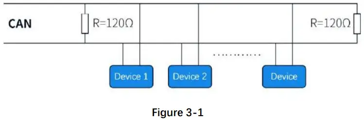
- When using CAN protocol to connect multiple devices, please refer to the connection method shown in Figure 3-1 below.。

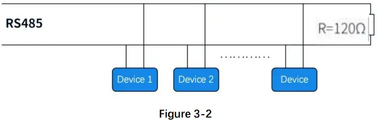
- When using RS485 protocol to connect multiple devices, please refer to the connection method in Figure 3-2 below, but the resistance value needs to be determined according to the number of devices connected by the user.

Chapter 4 Technical Service
Nanjing Runze Fluid Control Equipment Co.,LTD
Tel +86-25-51197362
Fax +86-25-51197362
Phone +86-138 5195 4068
Technical support +86-183 5195 5944, +86 -198 2581 4316
Official URL http://www.runzeflulid.com
Alibaba Store URL https://runzeliuti.en.alibaba.com
Sales Email [email protected]
Address NO.9 Tianxing West Road, Dongshan Street, Jiangning District
Nanjing, Jiangsu, China
 |  |  |
![]() NANJING RUNZE FLUID CONTROL EQUIPMENT CO.LTD
NANJING RUNZE FLUID CONTROL EQUIPMENT CO.LTD
www.runzeliuti.com


