![]() SY-01 Syringe Pump Quick
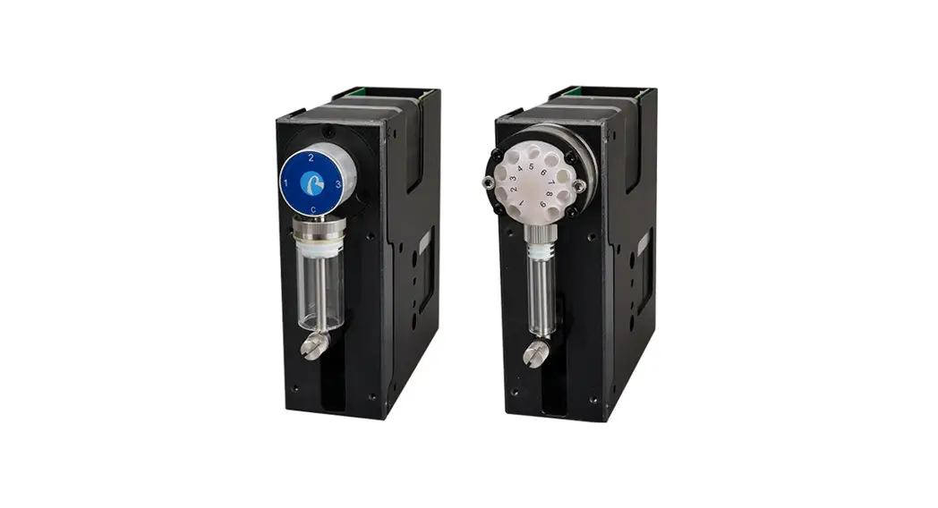
SY-01 Syringe Pump Quick
Use Guide
Please read the following notes carefully and follow it strictly for correct and safe use of product.
Item list
| Name | Quantity |
| SY-01 Syringe Pump | 1 set |
| DB15 Cable with Shell and Cabe | 1 pc |
| Operation Video and User Manual QR Code | 1 sheet |
| Certificate of Conformity | 1 sheet |
| Stroke Accuracy Test Report | 1 sheet |
| Syringe (optional) | Already installed on the syringe pump |
Cable Connection and Debugging
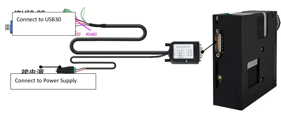
2.1 Power Cable and Communication Cable
| Item | Color |
| RS232 communication cable | Blue and white-GND, black and white-TX, orange and white-RX |
| RS485, CAN communication cable | Orange-B, blue-A, green-H, yellow-L |
| Power cable | Red-positive polar, black-negative polar |
Notes: CAN communication is not supported in the current software version
2.2 USB Driver and Debugging Software Installation
If you are using our USB To RS232/RS485 debugger for the first time, please download the debugger driver from the official website
- Login to the official website (http://www.runzeliuti.com)Click on the hyperlink to go directly to
the download page; - Download”->”Debug Tools”->”USB to RS232, RS485 converter driver “Click to download
- Driver installation
 Open the application file, confirm it is the CH341SER.INF file, click Install, and then click OK, the installation is complete.
 - Download Debugging Software
Quick Use
3.1 Debugging Software
Open the debugging software serialcomm, Figure 3-1-1 baud rate is the baud rate of the slave computer, the factory default is 9600bps, after setting the serial port and baud rate, click the “Port” button, then click on the Command Generator icon![]() in the top left or click on the Tools button to open the Command Generator
in the top left or click on the Tools button to open the Command Generator
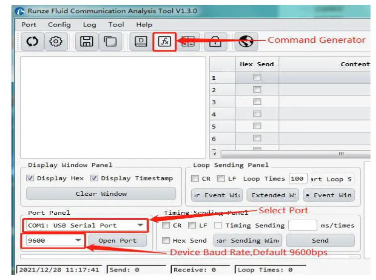 Figure 3-1-1
In the command generation tool, input the address, command, parameters, the command corresponds to various command codes of B2, parameters correspond to B3, B4, if it is a factory command, you need to check the factory mode, if it is a general command is not necessary to check. After setting, click Generate and Copy, the command display box on the right can show the current generated code and has been copied in the clipboard, as shown in Figure 3-1-2 below.
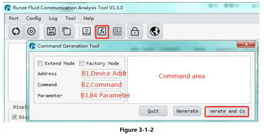
Note: The input of address, command and parameter boxes are all in hexadecimal.
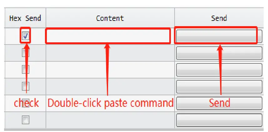
Return to the main interface of debugging software, double-click the input box under “content”, right-click to paste the copied command or use the shortcut key ctrl+V to paste the copied command. Then check the “hex send” ahead and click the blank button in the corresponding line under “send” to send the command.
3.2 Examples of Communication
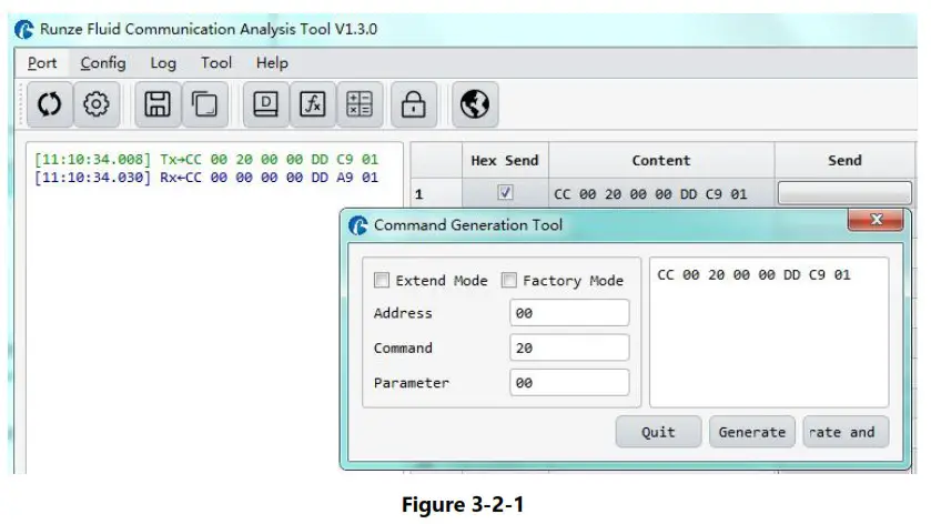
- Send Command: 0x20 query the device address
 Paste the copied command into the blank space below “Content”, check the Hex send box in front, then click send, there is a receive command means the device is connected successfully, receive command B3=00, B4=00, which means the current address of the device is 0.
 - Send command:0x45 Reset pump
 Paste the copied command into the blank space below “Content”, check the hex send box in front, then click send and get the return code and B2 byte is 00, then the pump reset is successful.
 - Send command: 0x43 aspirating
 Paste the copied command into the blank space below “Content”, check the hex send box in front, then click send and get the return code and B2 byte is 00, then the pump reset is successful.
Note: To switch between RS232 and RS485 communication modes, please turn the dial code on the USB-30 to the corresponding position.
 Paste the copied command into the blank space below “Content”, check the Hex send box in front, then click send, there is a receive command means the device is connected successfully, receive command B3=00, B4=00, which means the current address of the device is 0.
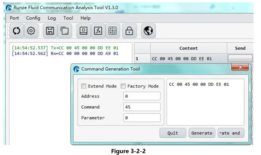 Paste the copied command into the blank space below “Content”, check the hex send box in front, then click send and get the return code and B2 byte is 00, then the pump reset is successful.
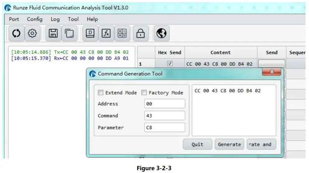 Paste the copied command into the blank space below “Content”, check the hex send box in front, then click send and get the return code and B2 byte is 00, then the pump reset is successful.
Quick Commands
| Code B2 | Abbreviation | Parameter Description B3 B4 |
| 0x20 | Query address | B3=0x00 B4=0x00 |
| 0xAE | Query current channel address | B3=0x00 B4=0x00 |
| 0x3F | Query current version | B3=0x01 B4=0x09, above is just an example, if the response parameter is the same as above parameter, it means the current version is V1.9, see the version number on the label for details |
| 0x4A | Query motor status | B3=0x00 B4=0x00 |
| 0x4D | Query valve status | B3=0x00 B4=0x00 |
| 0x42 | Discharge liquid | When the number of steps corresponding to parameter B3B4 is greater than the maximum number of steps, the motor will not run, and return byte B3=08, B4=00; When the number of steps corresponding to B3B4 |
| parameter is set to be less than the maximum number of steps, the motor rotates according to the set number of steps. | ||
| 0x43 | Aspirate liquid | When the number of steps corresponding to parameter B3B4 is greater than the maximum number of steps, the motor will not run, and return byte B3=08, B4=00; When the number of steps corresponding to B3B4 parameter is set to be less than the maximum number of steps, the motor rotates according to the set number of steps. |
| 0x44 | The valve rotates through the code disc to automatically select the optimal path | It depends on the actual number of channels/ports of the switching valve, such as 10 channel switching valve, then B3=0xXX B4=0x00 where XX ranges from 01 to OA |
| Ox4C | Valve reset | B3=0x00 B4=0x00 The switching valve runs to the reset optocoupler and stops |
| 0x45 | Reset syringe pump | B3=0x00 B4=0x00 The syringe pump runs to the home position and stops |
| Ox4F | Forced reset of syringe pump | B3=0x00 B4=0x00 The switching valve runs to the encoder home position, which overlaps with the position reset by the 0x45 command |
| 0x49 | Force Stop (syringe pump and valve) | B3=0x00 B4=0x00 |
| Ox4B | Set dynamic speed | B3B4 ranges from Ox0001 to Ox01C2. The speed of motor is 1 – 450 |
Common Problems & Solutions
| Phenomenon | Problem | Solution |
| Not working when power on | The working voltage is not in the acceptable range. | Test whether the voltage is within the specified range |
| The connection is loose or disconnected. | Check whether the connection is good. | |
| The working current is not in the acceptable range. | Detect whether the current is within the specified range | |
| Sending a command without a return code | Chose the wrong serial port | Please check the corresponding serial port via Device Manager |
| The TX and RX lines of RS232 are connected reversely or phase A & | Exchange the TX and RX line sequence of RS232 and exchange |
| B of RS485 are connected reversely. | the phase A & B sequence of RS485. | |
| The sent and received communications are consistent in RS232. | TX and RX are in short circuit. | Check whether there is short circuit, if so, replace the cable. |
| Working but the sent and received communications are consistent in RS485, | AB reversed, and the USB converter is not dialed to RS485 | Switch AB and dial USB to RS485 communication |
Installation and Use
- Applicable power supply: 24V±10%,3A, When using a linear power supply, the voltage and current must be adjusted to the corresponding parameter values
- Please use RUNZE debugging software serialcomm for product debugging
- While debugging, try to debug over liquid to avoid dry wear of the spool, which will affect the service life of the valve
- While using this product, please connect to GND to reduce the interference brought by environmental factors
- When not using this product, remember to clean the valve ports with cleaning solution such as alcohol or water to avoid long periods of test residue in the valve passage, resulting in port blockage.
- When installing this product, please install it on the existing installation holes, additional holes are strictly prohibited. For special requirements, please consult sales or technical support.


