![]() Analysis instrument accessories
Analysis instrument accessories
Ecological closed loop service provider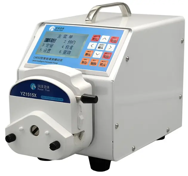
LM60A Intelligent Peristaltic Pump
Instruction Manual
Chapter 1 Product Introduction
1.1Overview
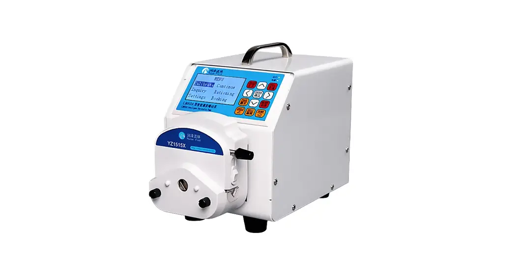
LM60A intelligent filling peristaltic pump, using high-performance processor and motor drive, controlling stepper motor, motor subdivision adaptive, the minimum speed can reach 0.1rpm; rich application scenarios, support keyboard control mode, communication control mode (RS232 /RS485), external control mode (optional multiple signal conversion modules); passive contact status output.
1.2Product Features
The product is composed of main machine, pump head, pump tube and other parts. The product can perform flow control, speed control, liquid volume control, and time control through the button panel. The four control modes are calibrating mode, continuous mode, rationing mode, booking mode.
The interface functions are clear and intuitive, and customers can perform various combined operations, which are convenient and simple.
Chapter 2 Instruction of Port and Structure
2.1 Technical Parameters
| Item | Parameters |
| Speed range | 0.1 ~ 300/400.0rpm (Maximum speed vary from different pump heads, tube types and tube sizes.) |
| Speed resolution | ± 0.1 rpm |
| Flow rate | 0.027 ~ 1380 ml / min |
| Pedal input port | foot switch control start/stop (keyboard control mode only) |
| Speed signal input port | support multiple speed control signal input (external control mode only) |
| Direction signal input port | Support steering switch control input (external control mode only) |
| Start signal input port | support start / stop signal input (external control mode only) |
| External communication control port | RS232 / RS485 (communication control mode only) |
| Power supply | DC24V±10% |
| Power consumption | 35W |
| Working environment | temperature 0-40 ℃, relative humidity < 80% |
| Dimensions (unit: mm) | 218 (length) × 148 (width) × 199 (height) |
| Weight | 3.5 kg |
| Protection grade | IP31 |
2.2 Overall Structure Diagram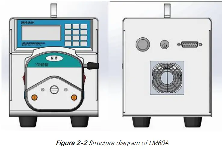
2.3 Definition of Communication Interface
| No. | Item | Description |
| 1 | +24V | DC24V Power Supply |
| 2 | RXD | RS232 Data output |
| 3 | TXD | RS232 Data input |
| 4 | COM | Passive contact output – common port |
| 5 | +5V | +5V Power supply |
| 6 | CB | Passive contact output –common close port |
| 7 | CK | Passive contact output –common open port |
| 8 | FT_EXST | Foot pedal/ external start stop signal input port |
| 9 | GND | Ground wire |
| 10 | EX_DIR | External steering signal input port |
| 11 | A | RS485-A port |
| 12 | B | RS485-B port |
| 13 | SWD-DIO | SWD Data |
| 14 | SWD-CLK | SWD Clock |
| 15 | ADC-IN | External speed signal input port(3.3V port) |
Table 2-3 DB15 external terminal attribute definition
2.4 Pump Head/Tube Selection
| Pump head | Applicable tube | Maximum flow rate | Maximum speed |
| YZ1515X-3X | 14#,16#,25#,17# | 1385ml/min | 400rpm |
| YZ1515X-6X | 14#,16# | 265ml/min | 400rpm |
| YZ2515X-3X | 15#, 24# | 1322ml/min | 400rpm |
| SN15-3 | 14#,16#,25#,17# | 1097ml/min | 300rpm |
| SN15-6 | 14#,16# | 180ml/min | 300rpm |
| SN25-3 | 15# | 551ml/min | 300rpm |
Table 2-4 Pump head / tube model and corresponding maximum flow reference
Note:
- Please refer to the flow chart in Chapter 6 before selecting the proper pump head and tube.
- The tube of the same size but different materials with different ductility, resilience and hardness will lead to difference of flow rate, so the maximum flow rate is only for reference.
- When using a tube with thicker wall (such as 24# tube), the current can be set to be larger, so as to increase the torque of the pump at high speed.
- When using a tube with thicker wall (such as 24# tube), the pump might be stalled when it starts at high speed after stopping working for a period of time. It is necessary to add lubricating oil and work at low speed for 1 to 2 minutes.
2.5 Special Function Switching
2.5.1 Restore factory settings: Press and hold the “edit” key to turn on the machine,
2.5.2 Chinese / English language interface switching: Press and hold the “CW / CCW” key to turn on the machine
2.5.3 Keyboard control mode: Press and hold the “HOME” key to turn on the machine and switch to the normal keyboard mode.
2.5.4 Communication control mode: Press and hold the “left” key to turn on the machine, supporting RS232 / RS485.
2.5.5 External control mode: Press and hold the “right ” key to turn on the machine, supporting external speed / steering / start input control.
2.5.6 Query version function: Press and hold the “Enter” key to turn on the machine, supporting the query of software version and software release time.
Chapter 3 Keyboard Control Mode
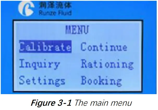
The main menu shows six functions, “Calibration”, “Continuous”, ” Rationing “, “Booking”, “Query” Setting”.
On the main menu, you can press “up”, “down”, “left” and “right” keys to switch functions.
On the main menu, when a function is displayed reversely, press the “Enter” key to enter the standby interface of the function; press “Edit” to enter the editing interface of this function.
On the editing interface, “up” / “down” changes the value, and “left” / “right” changes the cursor position. Press the “Home” key, if the edited value is wrong, an error message will be prompted and return to the main menu after three seconds. If the input value is correct, it will return to the main menu immediately after saving. Press the “Enter” key, if the edited value is wrong, an error message will be prompted. If the parameter is input correctly, it will return to the standby interface immediately after saving.
On the main menu or standby interface, press the ” ANGLE ” key to quickly enter the suction angle editing interface. The direction keys can change the value or cursor position, and press “Enter” or “HOME” key to save.
3.2 Working Mode Description
3.2.1 Calibration Mode
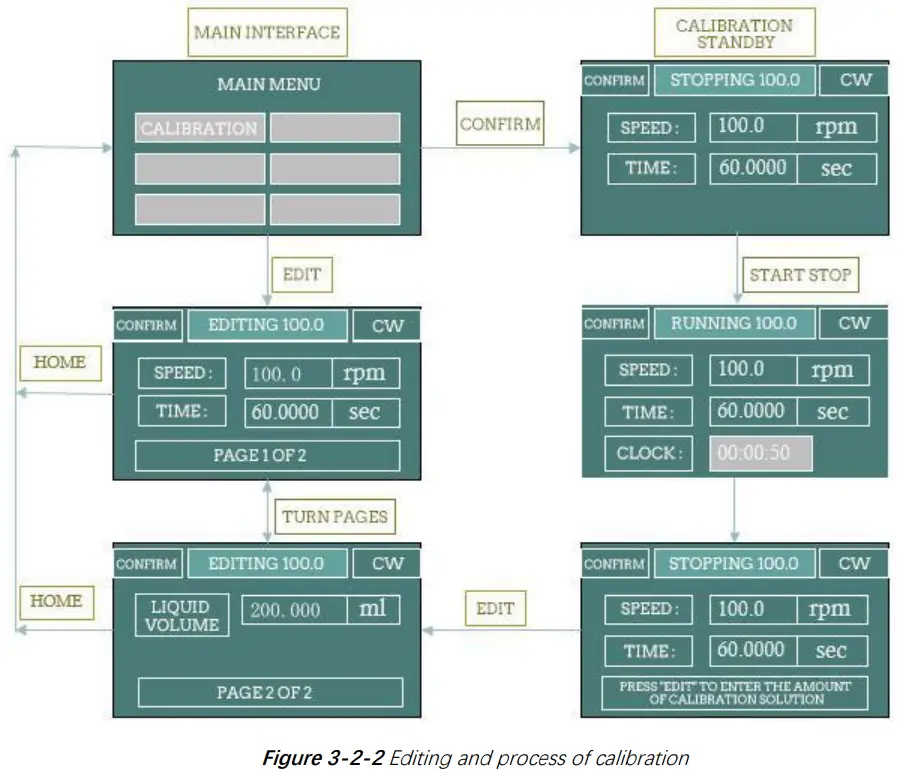
After the instrument is used for the first time, or after the pump head or pump tube is replaced, in order to obtain an accurate liquid volume result, it is necessary to perform a “calibration” operation and input the calibration result. The specific calibration process is as follows: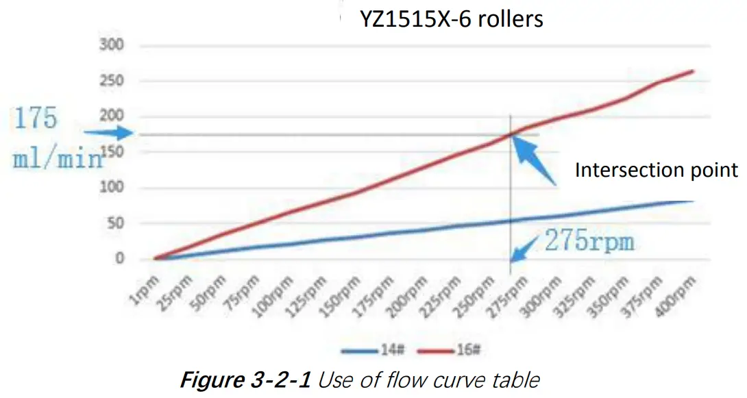
- Determine calibration speed. According to the flow rate you need, query the flow curve of the corresponding pump head / tube (Chapter 6 flow curve) to obtain the approximate calibration speed.
Take YZ1515X-6 wheel and 16# tube as an example. If you need a flow rate of 175ml / min, find the approximate position of 175ml / min on the longitudinal axis, make a horizontal line intersecting with the red line of the flow curve of the 16# tube, make a vertical line from the intersection point to the horizontal axis, and the intersection point with the horizontal axis is the calibrated target speed (about 275rpm). - Edit calibration parameters. On the calibration editing interface, input the calibration speed and calibration time, set the liquid volume to 0, and press the “Enter” key to save.
- Perform calibration process. Press the “CW/CCW” key, select the required steering direction, pre fill the tube, and empty the liquid in the receiving container. In the calibration standby interface, press the “ON/OFF” to start the peristaltic pump. After running the “calibration time”, the dispensed liquid volume is the ” volume” of this calibration. Use the measuring cup to read the milliliter of dispensed liquid.
- Input calibration data: after calibration, press the “Edit” to input the above calibration data (ml of liquid volume), and press “Enter” to save. After that, the system will automatically return to the main interface. When saving, if it displays “maximum flow overflow default value!”, you need to check the calibration process again to see if the test value is wrong.
Note: The calibration time of the pump is 60 seconds by default. You can also extend it appropriately. Repeat the test for many times to obtain the average value of the liquid volume obtained from multiple calibrations, which can improve the accuracy of the calibration results.
3.2.2 Inquiry Mode
Parameters such as standard speed, standard flow, minimum flow, maximum flow and standard ratio can be queried.
3.2.2.1 Calibrated speed
Last calibrated speed value. The default is 100.0 rpm
3.2.2.2 Standard flow
After the calibration, the system automatically calculates the calibrated flow under the correct input of the calibrated speed and the liquid volume value under the fixed time. Flow unit: ml / min.
3.2.2.3 Minimum flow
According to the calibrated speed, minimum speed (0.1 rpm) and calibrated flow, the system automatically calculates the minimum flow
3.2.2.4 Maximum flow
According to the calibrated speed, maximum speed and calibrated flow, the system automatically calculates the maximum flow.
3.2.2.5 Calibration ratio
Calibration ratio = calibrated flow / calibrated speed. Calibration ratio unit: ml / r. This is a reference unit for calculation.
3.2.3 Setting Mode
Parameters such as maximum speed, one key full speed, backlight time, contrast, current code and foot switch working mode can be set on the editing interface.
3.2.3.1 Maximum speed
It is the upper limit of motor speed. The maximum speed of the pump is generally related to the pump head model / pump tube model, which generally does not need to be changed. If the maximum speed is changed, it is necessary to recalibrate and input the calibrated value correctly.
3.2.3.2 Full speed
That is the speed of the motor when the motor is on the standby interface and press the “full speed” key. This function is generally used for emptying / filling. In order to ensure the stable running of the pump, the full speed is generally lower than the maximum speed.
3.2.3.3 Backlight time
This is the retention time after the backlight is turned on, in second (SEC). Each time you press the new key, the backlight retention time is recalculated.
3.2.3.4 Contrast
Contrast is used to adjust the brightness of the LCD screen.
3.2.3.5 Current code
The current code is used to set the maximum current of the motor.
Definition table of current code as below:
| Current Code | Maximum motor output current (A) | Effective motor output current (A) | Current Code | Maximum motor output current (A) | Effective motor output current (A) |
| 7 | 1.000 | 0.700 | 20 | 2.625 | 1.840 |
| 8 | 1.125 | 0.790 | 21 | 2.750 | 1.925 |
| 9 | 1.250 | 0.875 | 22 | 2.875 | 2.013 |
| 10 | 1.375 | 0.960 | 23 | 3.000 | 2.100 |
| 11 | 1.500 | 1.050 | 24 | 3.125 | 2.188 |
| 12 | 1.625 | 1.140 | 25 | 3.250 | 2.275 |
| 13 | 1.750 | 1.225 | 26 | 3.375 | 2.363 |
| 14 | 1.875 | 1.300 | 27 | 3.500 | 2.450 |
| 15 | 2.000 | 1.400 | 28 | 3.625 | 2.540 |
| 16 | 2.125 | 1.490 | 29 | 3.750 | 2.625 |
| 17 | 2.250 | 1.575 | 30 | 3.875 | 2.710 |
| 18 | 2.375 | 1.660 | 31 | 4.000 | 2.800 |
| 19 | 2.500 | 1.750 | – | – |
Table 3-2-3 Comparison table of current code and maximum motor output current
3.2.3.6 Foot switch
There are three states of foot switch: disabled, inching and linked switch.
Disable: The foot switch is disabled.
Inching: in “continuous” mode, the motor will run when the foot switch is stepped down, and the motor will stop when it is released.
Linked: in “continuous” mode, when the foot switch is stepped down and released, the motor will run; when it is stepped down again and released again, the motor will stop.
In other modes, the foot switch only serves as a start /stop function
3.2.4 Continuous Mode
In continuous mode, the machine has been through the normal calibration process by default.
3.2.4.1 Adjust speed in continuous mode
In continuous mode, the motor is allowed to work continuously. The direction of rotation of the motor can be adjusted to CW / CCW. The motor speed can be changed by setting the flow rate to achieve the purpose of changing the flow rate. When the pump is running, the speed can be changed by ± 0.1 rpm by “up” and “down”; and can be changed by ± 1 rpm by “left” and “right”; you can also press any one of direction keys and hold it for 1 second without release to realize the rapid change of
3.2.5 Rationing Mode
In rationing mode, the machine has been through the normal calibration process by default.
- On the main menu, select “Rationing” and press “Edit” to enter the rationing editing interface.
On the main menu, select ” Rationing ” and press “Enter” to enter rationing standby interface. - On the rationing editing interface, input the required liquid volume and time, and press “Enter” to save, and automatically jump to the standby interface.
- On the Rationing standby interface, press “ON/OFF” to realize a rationing process
3.2.6 Booking Mode
In booking mode, the machine has been through the normal calibration process by default.
Realize the function of “waiting-running 1-interval-running 2-interval-… running n”. You can set the value of N (N = 0000 for infinite loop, the maximum can be set to 9999) and you can also set the corresponding liquid volume and corresponding running time (related to the speed and calibration ratio).
| Booking Mode | Action | Result |
| Waiting | Press ON/OFF” | End the booking process and start running 0001# directly. |
| Press “HOME” | Exit the booking process and return to the main menu. | |
| Running | Press ON/OFF” | End the running time and enter the suspension. If it is the last run, the pump will automatically end the booking process. |
| Interval | Press ON/OFF” | End this interval and enter the suspension. |
| Suspension | Press ON/OFF” | Enter the next running process. |
| Press “HOME” | Exit the booking process and return to the main menu. |
Table 3-2-6 List of function keys “ON/OFF” and “HOME” during the booking process
Chapter 4 Communication Control Mode
4.1 Command Format
4.1.1 Common Command Format (send 10 bytes, return 10 bytes)
Byte send:
| 1 | 2 | 3 | 4 | 5 | 6 | 7 | 8 | 9 | 10 |
| FH (Frame header) | Address code | Function code | Function parameters | EOF (End of frame) | Cumulative sum | ||||
| STX | ADDR | FUNC | 1-8 bit | 9-16 bit | 17-24 bit | 25-32 bit | ETX | Low byte | High byte |
st The 1 byte STX: frame header (CCH) nd
The 2 byte ADDR: slave address (01H~ F7H) rd
The 3 byte FUNC: function code th The 4-7 bytes: parameters corresponding to the function code th
The 8 byte ETX: end of frame (DDH) th th
The 9 -10 bytes: cumulative sum check code from byte 1 to 8
Byte return:
| 1 | 2 | 3 | 4 | 5 | 6 | 7 | 8 | 9 | 10 |
| FH (Frame header) | Address code | State code | State parameters | EOF (End of frame) | Cumulative sum | ||||
| STX | ADDR | STATE | 1-8 bit | 9-16 bit | 17-24 bit | 25-32 bit | ETX | Low byte | High byte |
The 1st byte STX: frame header (CCH)
The 2 nd byte ADDR: slave address (01H~ F7H)
The 3 byte STATE: state codeth
The 4-7rd bytes: parameters corresponding to the state code
The 8 th byte ETX: end of frame (DDH)
The 9th -10 bytes: cumulative sum check code from byte 1 to 8
4.1.2 Factory Command Format (send 14 bytes, return 8 bytes)
Byte send:
| 1 | 2 | 3 | 4-7 | 8 | 9 | 10 | 11 | 12 | 13 | 14 |
| FH (Frame header) | Address code | Function code | Pass word | Function Parameters | EOF (End of frame) | Cumulative sum | ||||
| STX | ADDR | FUNC | 1-8 bit | 9-16 bit | 17-24 bit | 25-3 2 bit | ETX | Low byte | High byte | |
The 1st byte STX: frame header (CCH)
The 2nd byte ADDR: slave address (01H~ F7H) The 3rd byte FUNC: function code
The 4-7th bytes: password of factory command
The 8th-11th bytes: parameters corresponding to the function code The 12th byte ETX: end of frame (DDH)
The 13th-14th bytes: cumulative sum check code from byte 1 to 12
Byte return
| 1 | 2 | 3 | 4 | 5 | 6 | 7 | 8 |
| FH (Frame header) | Address code | State code | State parameters | EOF (End of frame) | Cumulative sum | ||
| STX | ADDR | STATE | 1-8 bit | 9-16 bit | ETX | Low byte | High byte |
The 1st byte STX: frame header (CCH)
The 2nd byte ADDR: slave address (01H~ F7H) The 3rd byte STATE: state code
The 4-5th bytes: parameters corresponding to the state code The 6th byte ETX: end of frame (DDH)
The 7th-8th bytes: cumulative sum check code from byte 1 to 6
4.2 Setting Command (suitable for factory command format)
The password to set the command is AABBEEFFH (the lower one comes first).
| Serial number | FUNC Code | Function | Parameter | Remark |
| 1 | 00H | Set the device address | 00000001H-000000F7H (1-247) | 0x00 is broadcast address and it only accepts, but does not reply. |
| 2 | 01H | Set RS232 baud rate | 00000000H-00000004H | 0:9600bps (Default) 1:19200bps 2:38400bps 3:57600bps 4:115200bps |
| 3 | 02H | Set RS485 baud rate | 00000000H-00000004H | |
| 4 | 03H | Set suction angle | 00000000H-00000E10H (0-3600 degrees) | Default 36 degrees. |
| 5 | 04H | Set direction | 00000000H~00000001H | 0:CCW 1:CW(Default) |
| 6 | 05H | Set maximum speed | 00000001H~0000FA0H (0.1~400.0rpm) | 10 times storage; fixed parameters (1~4000); default 3000 |
4.3 Query Command(suitable for common command format)
| Serial number | Function code | Function | Parameter | Remark |
| 1 | 20H | Query the device address | No parameter | The slave does not recognize the command address, and when one more device with RS485, the query address has the risk of hardware conflict. |
| 2 | 21H | Query RS232 baud rate | No parameter | |
| 3 | 22H | Query RS485 baud rate | No parameter | |
| 4 | 23H | Query suction angle | No parameter | |
| 5 | 24H | Query storage steering | No parameter | |
| 6 | 25H | Query maximum speed | No parameter | 10 times storage,stability of the system |
Table 4-3 List of query command
4.4 Control command(suitable for common command format)
| Serial number | FUNC Code | Function | Parameters | Remarks |
| 1 | 40H | Take a few steps clockwise | 00000001H-FFFFFFFFH | |
| 2 | 41H | Take a few steps counterclockwise | 00000001H-FFFFFFFFH | |
| 3 | 42H | Take a few steps clockwise. At the end, it runs according to the suction angle setting. | 00000001H-FFFFFFFFH | |
| 4 | 43H | Take a few steps counterclockwise. At the end, it runs according to the suction angle setting. | 00000001H-FFFFFFFFH | |
| 5 | 44H | Turn the specified circle clockwise | 00000001H-FFFFFFFFH | |
| 6 | 45H | Turn the specified circle counterclockwise | 00000001H-FFFFFFFFH | |
| 7 | 46H | Query motor status(Number of cycles left) | random | Return current status. The parameter is the number of cycles left. |
| 8 | 47H | Turn continuously clockwise | random | The returned status parameter is 0. |
| 9 | 48H | Turn continuously counterclockwise | random |
| 10 | 49H | Forced to stop | random | The returned status parameter is 0. |
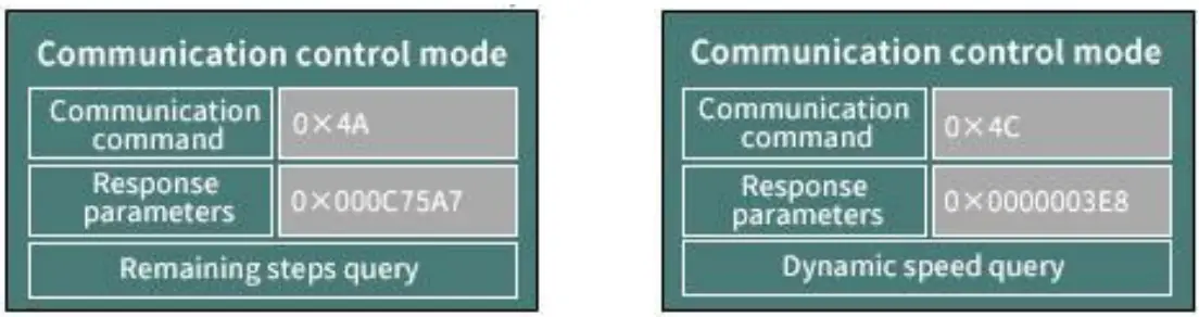
| 11 | 4AH | Query motor status(Number of steps left) | random | Return current status. The parameter is the number of steps left. |
| 12 | 4BH | Set dynamic speed | 0001H~FA0H 0.1rpm~400.0rpm) | 10 times the actual speed value |
| 13 | 4CH | Query dynamic speed | random | Return 10 times the dynamic speed |
Table 4-4 List of control command(include the command of Query status)
4.5 Communication Control Mode Interface
4.5.1 Control command (example)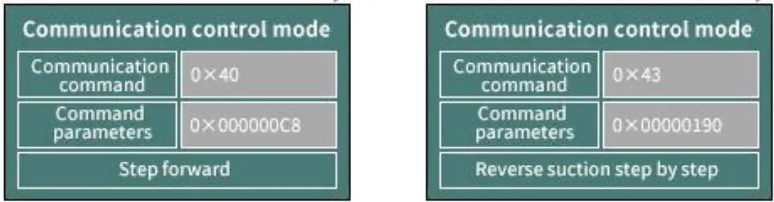
Figure 4-5-1-1 CW 0xC8(200 Steps)
Figure 4-5-1-2 CCW 0x190 (400 Steps) with suction
4.5.2 Status query command (example)
4.5.3 Set command (factory command) and query (example)
Setting address interface (address setting command is 0x00, address query command is 0x20)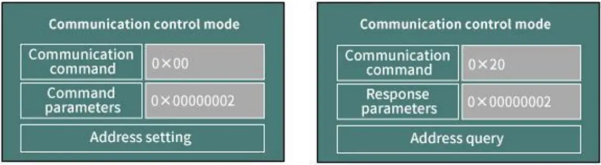
Figure 4-5-3-1 address setting interface
Figure 4-5-3-2 address query interface
Chapter 5 External Control Mode
5.1 External Speed Control Operation
- Press and hold the “right” key to switch to external control mode. The default is in the stop state of the external control mode.
- Press the “ON/OFF” on the keyboard or the middle button of the rotary encoder to switch between start and stop.

- When the motor stops, press “up” or “down” key to switch the type of external control signal
The definition of adjusting speed signal code as follows Figure 5-1-3 when motor stops, press “up” or “down” key to switch the type of signal
 - When the motor stops, press “CW/CCW” key to change the direction.
 Figure 5-1-4 When the motor stops, press “CW/CCW” key to change the direction
 - The external steering input port EXDIR can switch the steering no matter when the motor running or not. Set EXDIR high (open circuit with ground) to turn CW, and set EXDIR low (short circuit with ground) to turn CCW.
- External start/stop input port EXST. Setting EXST high (open circuit with ground) prohibits rotation, and setting EXST low (short circuit with ground) allows rotation.
- External speed control input port ADC-IN can adjust signal. The port voltage is 0 ~ DC3.3V. If you want to input other speed control signals, the corresponding signal converters need to be connected for correct operation.
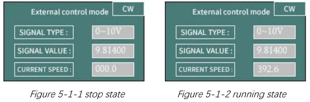
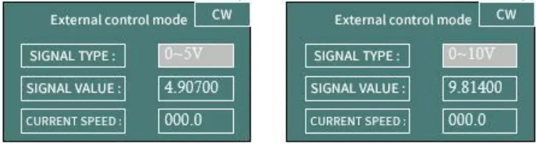 Figure 5-1-3 when motor stops, press “up” or “down” key to switch the type of signal
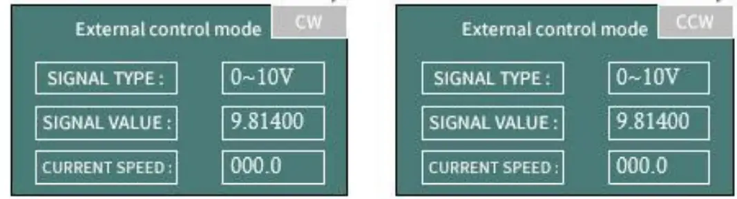 Figure 5-1-4 When the motor stops, press “CW/CCW” key to change the direction
| External speed control signal | Definition | Remark |
| 0 | 0-3. 3V external speed control | The voltage signal of 0 ~ 3.3V can be directly connected to the ADC-IN port |
| 1 | 0-5V external speed control | Special conversion module from 0 ~ 5V to 0 ~ 3.3V is required |
| 2 | 0-10V external speed control | Special conversion module from 0 ~ 10V to 0 ~ 3.3V is required |
| 3 | 4-20mA external speed control | Special conversion module from 4 ~ 20mA to 0 ~ 3.3V is required |
| 4 | 0-10KHz external speed control | Special conversion module from 0 ~ 10KHz to 0 ~ 3.3V is required |
Table 5-1 List of external speed control signal
Note: the external control speed can only be adjusted between 0-maximum speed. Due to the error of AD, the actual minimum speed will be greater than 0.1 rpm, and the actual maximum speed will be less than the theoretical maximum speed.
5.2 Maximum Speed Setting
When the motor stops, set the maximum speed through RS232 / RS485, please refer to the command of 0x05 in Chapter 4.2.
When the instrument leaves the factory, the suitable maximum speed will be preset according to the optional pump head/pump tube. The user does not need to set.
Chapter 6 Technical Parameters of Peristaltic Pump Tube
6.1 Table of Commonly Used Flexible Tube
| Model | LM60A | ||||||
| Tube number | 14# | 16# | 25# | 17# | 15# | 24# | |
| Wall thickness(Metric:mm) | 1.6 | 2.4 | |||||
| Wall thickness(Inch) | 1/16” | 3/32” | |||||
| Inner Diameter(Metric:mm) | 1.6 | 3.2 | 4.8 | 6.4 | 4.8 | 6.4 | |
| Inner Diameter(Inch) | 1/16” | 1/8” | 3/16” | 1/4” | 3/16” | 1/4” | |
| Pressure (Mpa) | Continuous | 0.17 | 0.14 | 0.10 | 0.17 | ||
| Short | 0.27 | 0.24 | 0.14 | 0.27 | |||
Table 6-1 table of commonly used flexible tube
6.2 Peristaltic Pump Head-Tube Reference Flow Curve
- YZ1515X-3 rollers (LM60A) flow-speed curve

- YZ1515X-6 rollers (LM60A) flow-speed curve

- YZ2515X-3 rollers (LM60A) flow-speed curve

- SN15-3 rollers (LM60A) flow-speed curve
 Figure 6-2-4 SN15-3 rollers (LM60A) flow-speed curve
 - SN15-6 rollers (LM60A) flow-speed curve

- SN25-3 rollers (LM60A) flow-speed curve
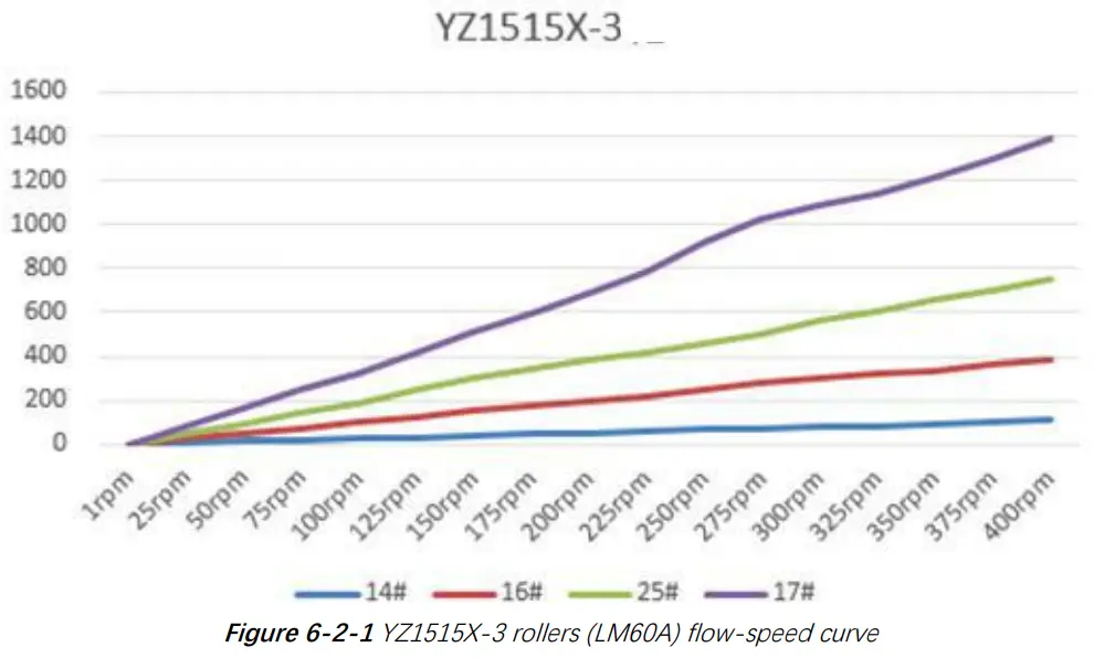
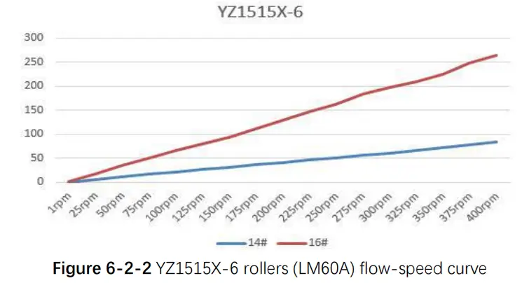
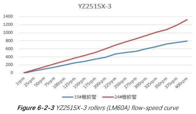
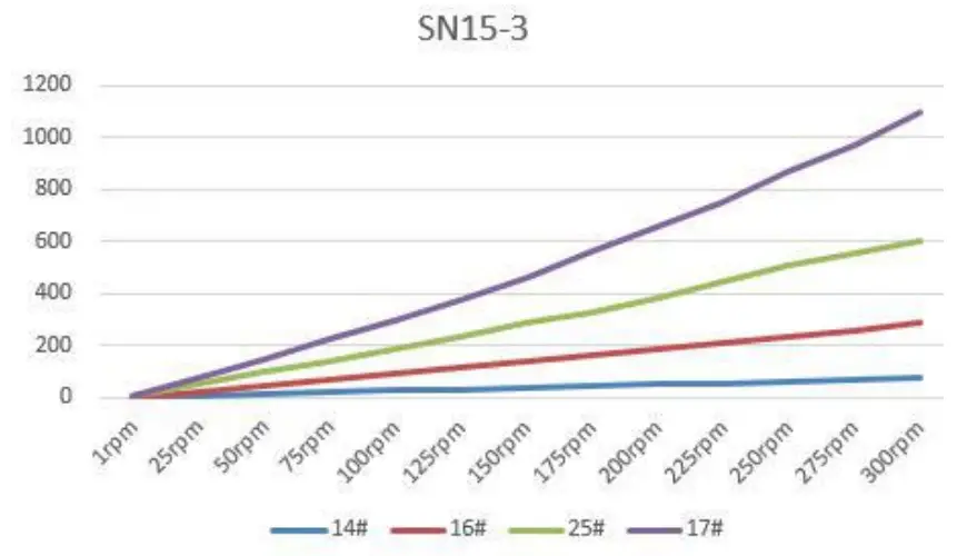 Figure 6-2-4 SN15-3 rollers (LM60A) flow-speed curve
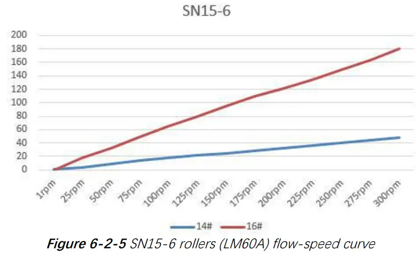
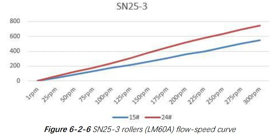
Figure 6-2-6 SN25-3 rollers (LM60A) flow-speed curve
Note 1: The above “Flow-Speed” of different pump heads and different tubes is the actual test curve, without any modification, for reference only;
Note 2: The above test liquid is water and the test temperature is 25 ℃
Note 3: There are many factors affecting the actual test data, such as the material and elasticity of the tube, the tightness of the tube installation, and the viscosity of the test liquid;
Note 4: The diameter and wall thickness of the pipe will affect the maximum speed that the motor can reach when the pump head runs stably;
Note 5: If high precision of dosing accuracy is required, please choose syringe pump or other high-precision products
Chapter 7 Equipment Maintenance
7.1 Common Equipment Maintenance Process
- Regular maintenance of tube
When the tube is not used for a long time, please empty the liquid in the tube in time, open the protective lock on the pump head and loosen the pump tube. - Check tube connectors regularly
Regularly check whether the tube connector is loose or damaged. If it is abnormal, it must be replaced in time - Regular or irregular calibration
Recalibration is necessary after the tube is replaced or loosened.
7.2 Common Problems and Solutions
| Problem | Problem description | Solution |
| The backlight is not on. | The value of “backlight time” in “settings” is set to 0 | Increase the value of “backlight time” in “settings”. |
| Failure of backlight hardware or backlight power control part | The backlight problem does not affect the normal use of the pump, and the backlight function is generally used in a dark environment. If it is a hardware failure, it is recommended to return to the factory for repair. | |
| Value of “Contrast” in “settings” is set to 1 | Increase the value of “Contrast” in “settings” | |
| Burred LCD screen | There are large disturbance sources nearby | When the instrument works, try to keep it away from the disturbance source |
| The position of data refreshed to LCD screen is out of order due to unknown reasons | The wrong display of the screen does not affect the normal operation of the motor control. If the motor is running, press the “ON/OFF” to stop the motor. On the standby interface, press the “HOME” for five times to refresh the screen display again. | |
| Fan does not rotate | The fan is too dusty and blocked | After the power is turned off, use a soft brush to remove dust |
| The fan is broken or the fan power supply is not in good contact | Return to factory for repair |
| Motor does not rotate | The screen shows that the motor works. In fact, the motor does not rotate. | Check whether the pump body joint is loose and reliable. |
| Check whether the current code in “settings” is too small. Set the current code consistent with the product. | ||
| The motor connecting wire is loose and return to the factory for repair. | ||
| Power wire is loose and return to factory for repair. | ||
| Motor stalled | The original pump head / tube can run at a certain speed, but the new pump head / tube cannot run. | The new pump head / tube should be run for one or two minutes at a lower speed. |
| The maximum speed of the motor suitable for the pump head / tube is exceeded. | Please refer to the above operation curve to select the reasonable speed corresponding to the pump head / tube. | |
| Inaccurat e flow or liquid volume | There is a big difference in the liquid volume or flow rate after replacing the tube. | Recalibrate and input accurate calibrated parameters. You can take the mean value after multiple calibrations, and then enter the mean value. |
| The tube has been used for a long time and its resilience has decreased | Replace the tube. | |
| Accuracy requirement is not appropriate. | The flow rate / speed / tube diameter are inversely proportional to the accuracy. Try to use smaller diameter tube. |
Chapter 8 Version Introduction
| Version | Description | Release time |
| V1.0 | Initial version | 2019-09-27 |
| V1.1 | 1. Add the corresponding table of current code 2. Correct the maximum speed of the motor corresponding to the tube 3. Modify the expression of “inquiry / setting / continuous mode”. | 2020-02-28 |
| V1.2 | 1. Delete commands with asterisk 2. Correct the use of RS232 interface 3. Updated header VI logo | 2020-8-26 |
| V1.3 | 1. The manual of LMA 60A / LM60B is separate. 2. Delete keyboard control mode, LM60B flow curve, weight, diagram, pump tube and other parameters. | 2020-10-9 |
Chapter 9 Technical Service
Tel : 025-51197362 Phone : 138 5195 4068
Fax : 025-51197362 Technical support : 183 5195 5944
Official URL : http://www.runzeflulid.com
Alibaba Store URL : https://runzeliuti.en.alibaba.com
Sales Email : [email protected]
Address : NO.9 Tianxing West Road, Dongshan Street, Jiangning District,
Nanjing, Jiangsu, China
 |  |  |
| http://www.runzefluidsystem.com | https://runzeliuti.en.alibaba.com/?spm=a2700.7756200.0.0.52dd71d2bqp0I8 |


