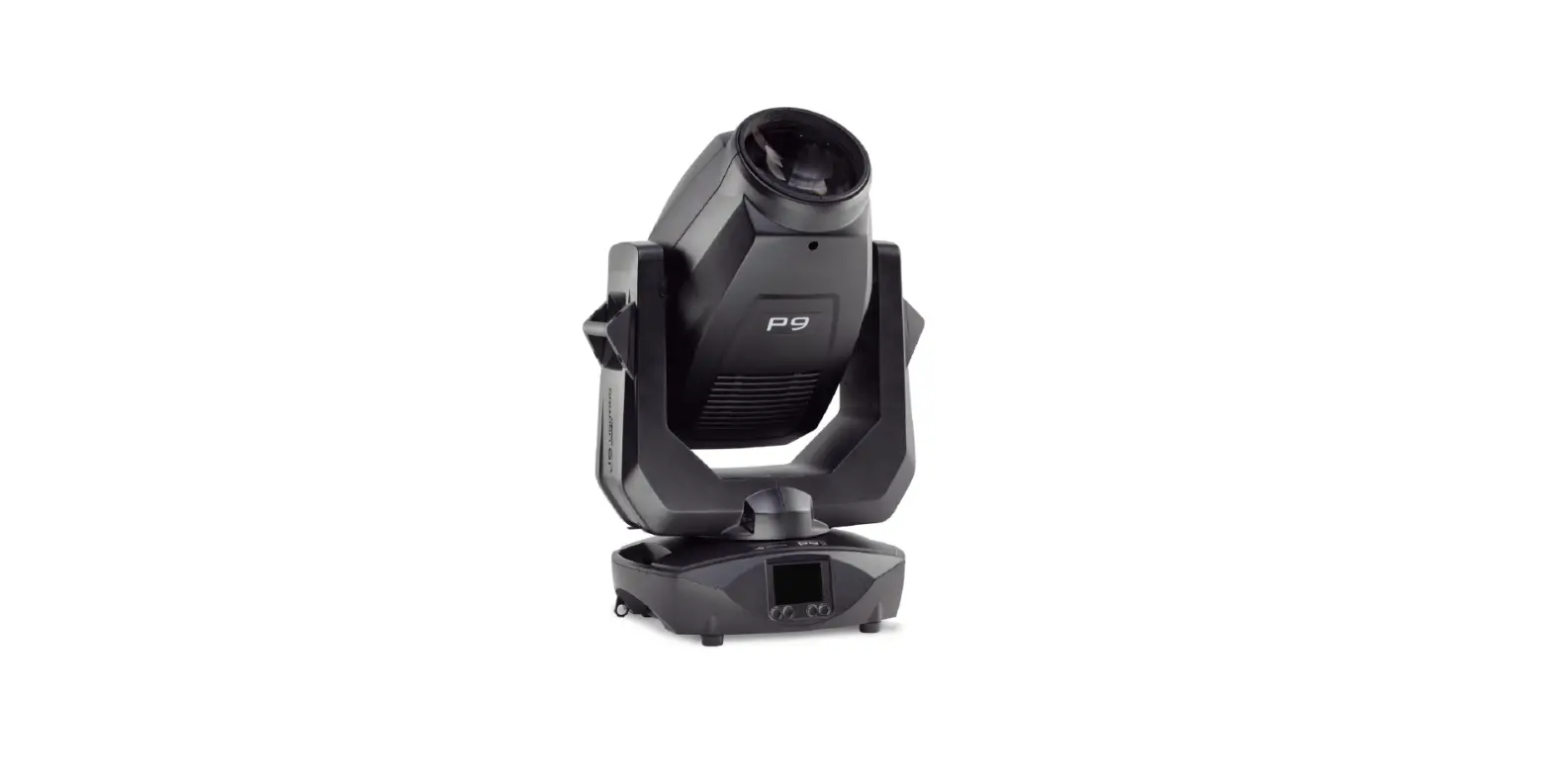
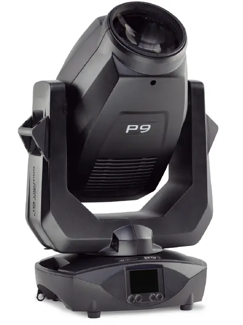
JB LIGHTING P9 Tree spot LED Moving Head
Introduction
P9 Beamspot models
The P9 beam spot is available in the light color HP (High Power). It can also be operated without any problems in the light colors 5800K (CRI> 90) and 3200K.
| Specification | HP – High Power | with High CRI filter | with CTO filter |
| Color temperature | 6800 K | 5800 K | 3200 K |
| Luminosity | 25.000 lm (15.000 lm output) | 10.000 lm output | 7.500 lm output |
| CRI | >= 70 | >= 90 | >= 85 |
Dimensions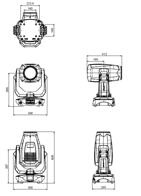
Product Overview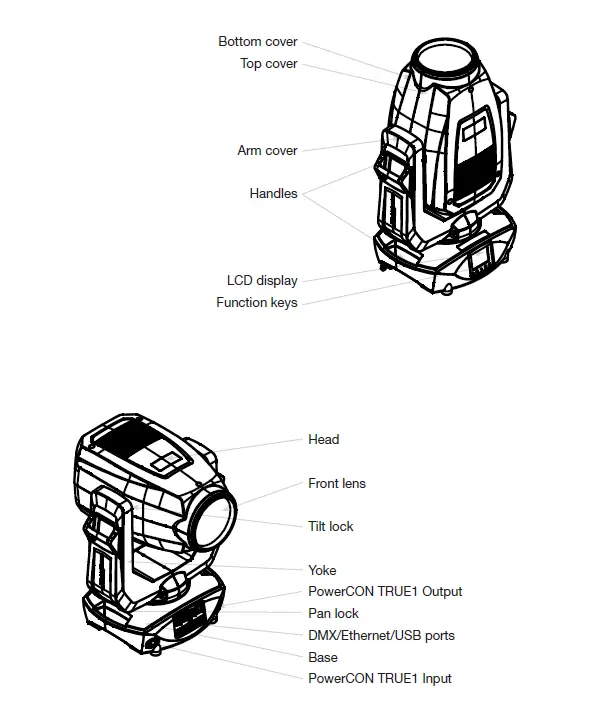
Safety instructions
ATTENTION: For your own safety, please read these operating instructions carefully before first use.
- This spotlight has left our company in excellent condition. To maintain this condition and to ensure safe operation, it is absolutely essential to observe the following safety instructions and warnings which are described in this operating manual.
- The manufacturer accepts no liability for damage caused to the device by disregard of these operating instructions or unauthorised modifications.
- Please note that damage caused by manual modifications to this unit is not covered by the warranty.
ATTENTION: This device is only suitable for professional use! Protection class IP 20 – only for use in dry environments (indoors)!
ATTENTION: JB-Lighting Lichtanlagentechnik GmbH does not authorise the use of its devices in life support systems. Life-supporting systems are systems whose purpose is to maintain or stabilise life and whose defect or malfunction may result in death or injury to persons.
The product in this manual complies with the following EU directives:
- Low Voltage Directive 2014/35/EU
- EMC Directive 2014/30/EU
ATTENTION: Disconnect the device from the power supply before opening the device. You can suffer an electrical shock from touching live parts (high voltage).
- Ensure that the mains voltage to be connected is not higher than that indicated on the type plate. This device should only be operated with the power source indicated on the type plate. If you are not sure what type of power supply you have, contact your dealer or power supplier.
- Always disconnect the device from the power supply before carrying out cleaning work or before replacing fuses or parts.
- The mains plug must always be accessible after the spotlight has been installed. Do not overload the sockets or extension cables as this could result in fire or electric shock.
- Do not place any objects on the power cable. Do not install the spotlight in such a way that people can trip over or step on the power cable. Make sure that the power cable can never be crushed or damaged by sharp edges. Check the unit and the power cable from time to time.
- Leave maintenance work to a qualified technician!
ATTENTION: This fixture corresponds to protection class I. For this reason, this spotlight must be connected to a mains socket with earthing contact.
- Never connect this device to a dimmer pack.
- During first use, some smoke and odour may occur. This is normal and does not necessarily mean that the device is defective.
- The device becomes hot during operation. Never touch the device with bare hands during operation!
- When replacing fuses, only use the same types with identical values! Only have fuse replacement carried out by a qualified technician
ATTENTION: DAMAGE TO EYES! Do not look into the light source for long periods during operation. This can be harmful to the eyes. Attention: potentially hazardous radiation – Risk group 2 based on DIN EN 62471
- If the device has been exposed to strong temperature fluctuations (e.g. after transport), the device must not be switched on immediately. The resulting condensation can damage your device. Leave the device switched off until it has reached room temperature.
- If the P9 Beamspot is operated below 0°, gobo/prism swapping and gobo/prism rotation are reduced in speed. This is a protective mechanism of the P9 Beamspot, as at low temperatures the lubricant is relatively viscous in the rotational mechanism and can therefore cause the effect to be slurred. From indoor temperatures of 1° and upwards, the spotlight runs normally! This temperature is quickly reached under normal operation (LED engine on).
- Do not shake or knock the device. Avoid brute force during installation or operation.
- This light was designed for indoor use only. Do not expose this device to rain or moisture.
- When choosing a mounting location, make sure that the device is not exposed to extreme heat, moisture or dust.
- Ventilation openings and slots in the head and foot of the spotlight are used for ventilation to ensure reliable operation of the device and to protect it from overheating, these openings must not be covered.
- Never cover the front lens when the spotlight is in use.
- The openings should never be covered with substances or other objects so that the airways are blocked.
- This device must not be operated in an environment without adequate ventilation.
- The device may only be operated when the housing is closed and all screws/Camlocs are firmly tightened.
- The device must always be secured with an additional safety device.
- Ensure that the area below the spotlight is clear during installation, alteration and removal.
ATTENTION: The distance between the light emission and the surface to be illuminated must be at least 2.0 metres.
The maximum ambient temperature of 45°C must not be exceeded.
ATTENTION: The front lens must be replaced if it is visibly damaged to the extent that its function is impaired, e.g. by cracks or deep scratches!
- Do not operate the device until you have become familiar with its functions. Prevent operation by persons who are not qualified to use the device. Most damage is the result of improper operation!
- Please use the original packaging or specially adapted flight cases if the device is to be transported. When using the original packaging, the locks must not be closed!
ATTENTION: To avoid damaging the internal parts of the light head, never let sunlight shine directly into the front lens.
Installation
Unpacking the device
Contents of the packaging: This spotlight, two Omega brackets with original Camloc fasteners, powerCON-TRUE1 cable and a safety note. These instructions are included in the shipment. Open the packaging at the top and remove the powerCON TRUE1 cable, the inlay and the safety instructions. The Omega brackets are located under the spotlight. Check the P9 Beamspot for possible transport damage. This should be communicated immediately to the transport company.
Fitting the plug to the connection cable
ATTENTION: Only have plugs installed by a specialist!
The P9 Beamspot is supplied with an assembled Schuko power cable with the powerCONTRUE1 plug (only the powerCON-TRUE1 plug is included in the US version). The installation of the power connection of the P9 Beamspot to the power supply (100-240 Volt, 50 – 60 Hertz) must be carried out by an authorised specialist.
Connection in Germany/Europe:
| Wire colour | Function | Symbol |
| Brown | Phase | “L” |
| Blue | Neutral wire | “N” |
| Green/Yellow | Protective earth | “PE” |
Connection outside Europe:
The P9 Beamspot may only be operated on the following power supply systems: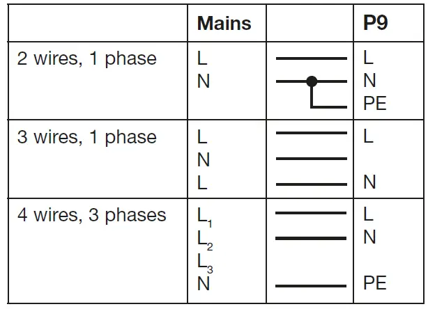
Mains connection
- Connected loads: Voltage 100-240 V, frequency 50 – 60 Hz, power max. 460 VA
- The electrical safety and function of the device can only be guaranteed if it is connected to a properly installed protective conductor system. It is very important that this basic safety requirement is met. If in doubt, have the electrical installation checked by a specialist. The manufacturer cannot be held responsible for damage caused by a missing or interrupted protective conductor (e.g. electric shock)! Only use the device when it is completely assembled so that no electrical components can be touched. (Danger 100-240 V)
- If you have observed the listed points, you can plug in the devices or have them connected to the mains by a specialist.
ATTENTION: The P9 Beamspot can light up immediately if standalone operation is activated or a DMX signal is present!
Wiring the power feed-through
ATTENTION: Only have it carried out by a specialist!
The P9 Beamspot has a powerCON-TRUE1 out power output. Depending on the local conditions several devices can be linked by powerCON-TRUE1 in and powerCON-TRUE1 out. Connect a maximum of six (when using 230V/16A) P9 Beam spots in a row. Use an approved three-core cable with a cross-section of at least 1.5 mm². Cabling must be done with the original Neutrik-coded plugs. The installation instructions of the manufacturer (www.neutrik.com) and the colour coding of the cable must be observed
| Wire colour | Function | Symbol |
| Brown | Phase | “L” |
| Blue | Neutral wire | “N” |
| Green/Yellow | Protective earth | “PE” |
Signal connections
DMX cabling
The DMX cabling (signal lines) should be done with a 4-pin cable with shielding. We recommend a DMX cable (110 Ohm, 2×0.22mm2 or 4×0.22mm2). The plugs and sockets are 5-pin XLR connectors, which can be purchased in specialist shops
Pin assignment: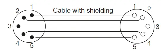
- Pin1 = Ground/Shielding
- Pin2 = DMX –
- Pin3 = DMX +
- Pin4 = not connected
- Pin5 = not connected
The P9 Beamspot has a DMX-in and DMX-out connector. Now connect the DMX output of your controller to the 1st P9 Beamspot (Controller DMX-Out -> P9 Beamspot DMX-In). Then the 1st P9 Beamspot with the 2nd P9 Beamspot (P9 Beamspot DMX-Out -> P9 Beamspot DMX-In) and so on. In some cases it is advisable to insert a so-called end connector (XLR connector with a 120 Ohm resistor between pin 2 and pin 3). Whether an end connector is required depends on various factors, including the cable lengths used and the number of devices. However, as long as no problems occur in the DMX line, this is not necessary.
Ethernet cabling
Ethernet cabling can be done with standard network lines. The sockets on the device are Neutrik etherCON sockets. Special cables with etherCON connectors are recommended by Neutrik. The two sockets on the P9 Beamspot are connected to each other via a switch. Up to 10 devices can be connected in series without any delay. Of course, the spotlights can also be supplied in a star configuration via an external switch. The received signal can be output via DMX. To do this, set the DMX OUTPUT CONFIG setting to ON in the PERSONALITY menu. After confirming with ENTER, the spotlight emits the entire universe received via DMX.
ATTENTION: Make sure that there is no signal at the DMX input at the same time !!
Wireless reception
The P9 Beamspot is equipped as standard with a LumenRadio CRMX receiver for wireless DMX. The receiver can process both DMX and RDM. If a cable and wireless connection are connected to the P9 Beamspot, the cable connection has priority! The received signal can be output via DMX. To do this, set the DMX OUTPUT CONFIG setting to ON in the PERSONALITY menu. After confirming with ENTER, the spotlight emits the entire universe received via DMX.
ATTENTION: Make sure that there is no signal at the DMX input at the same time
Mounting the devices
ATTENTION: Allow a fixture distance of at least 0.5 metres from easily flammable material and the distance between the light emission and the surface to be illuminat-ed must be at least 2.0 meters.
- The P9 Beamspot can be placed on the floor or hang on a trussing system. Also a mounting horizontally to a truss system like in the picture is only allowed with our special mounting plate.
- When placing the unit on the floor make sure that it stands on rigid ground, because the air inlets in the base must not be covered with anything!
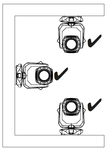
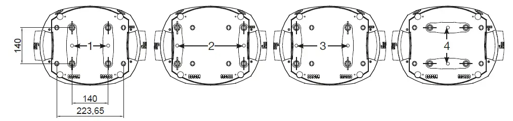
- To mount the unit on a trussing system use two of the original JB-Lighting omega brackets with original Camloc-connectors. You have following four possibilities to mount the omega brackets.
- The Camlocs must snap in to be locked properly. Ensure that the structure (truss) to which you are attaching the fixture is secure. If you install the fixture to a truss always attach a safety cable, that can hold at least 10 times the weight of the fixture.
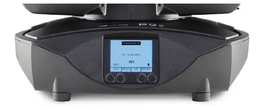
Control panel
- The P9 Beamspot has a graphic colour touch display that can be rotated 180° when installed in a suspended position. The display can be rotated in the PERSONALITY MENU or via shortcut ENTER + UP in the main screen.
- All parameters of the P9 Beamspot can be set on the control panel (see menu overview page 16).
Function and operation of the display
- The main menu provides information regarding the set DMX mode and, when the wireless mode is switched on, the field strength of the associated transmitter module. “ENTER” calls up a sub-menu or confirms an input. “ESC” is used to exit a function or a menu item. “UP” and “DOWN” are used to navigate within the menu and to enter values.
- Special areas can only be called up using a specific key combination. To do this, press and hold the “ENTER” key and then use the opposite “ESC” key to access the menu.
- To exit the function, proceed in reverse order.
- This applies in the SERVICE area for the FINE ADJUST function and in the STANDALONE area for the MODIFY, RUN and REMOTE functions.
- The main menu can also be locked to prevent unintentional access. It is also locked by pressing the “ENTER” key (keep it pressed) and then additionally locking it with the opposite “ESC” key.
- From software 1.5 onwards, all functions can also be operated via the touch display.
Display illumination as function display
- The display illumination remains switched off during the reset. Slowly flashing display illumination when “JB-Lighting” is displayed means no DMX signal is present.
- A very rapidly flashing display illumination when “JB-Lighting” is displayed means that a new error has been stored in the “ERROR LIST”, also an error message in the display (e.g. *PAN TIMEOUT) indicates this current error. This error occurs during this reset or in the operation before. This error is now automatically set to “read”, but remains in the “ERROR LIST”.
- A rapidly flashing display illumination shows an error in the “ERROR LIST” is still in it but has already been confirmed or was automatically confirmed. Only when the error has been deleted from the ERROR LIST does the P9 Beamspot start again without error signalling.
- If errors occur again and again contact the dealer / distributor or our service department.
- If the P9 Beamspot receives a DMX signal, the display illumination goes out after 30 seconds.
- Further settings for the display illumination see page 20 BACKLIGHT MODE.
DMX addressing
- In the main menu, the DMX address can be set directly by pressing the up/down keys.
- Display operation via battery backup
- By pressing the left button below the display, the configuration battery operation of the headlamp is activated, so the headlamp can be configured without power. It is possible to configure all the settings displayed by the menu, for example the DMX address can be set.
Menu overview P9 Beamspot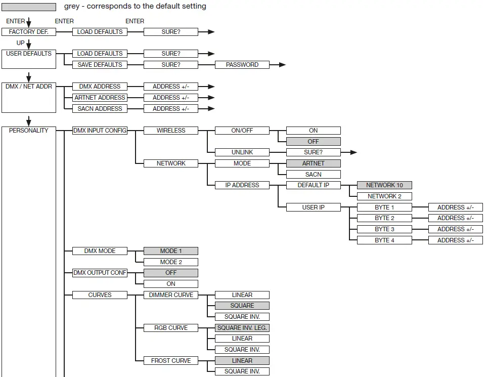
FACTORY DEFAULTS – Factory settings
To reset P9 Beamspot to the factory settings, go to the menu item FACTORY DEFAULTS, LOAD DEFAULTS. After confirming the security prompt SURE? with pressing “ENTER” for 2 seconds, all parameters are reset to the factory settings.
USER DEFAULTS – User settings
If the user has set the P9 Beamspot in the PERSONALITY menu to their personal settings, these can be saved and loaded in the USER DEFAULTS menu. In order to prevent unintentional alteration of the data, you must enter the following password during the saving process: Buttons “ESC DOWN UP ENTER”.
DMX / NET ADDRESS – DMX addressing / Artnet addressing / sACN addressing
The DMX addressing can be done either directly in the display. Press the “UP” or “DOWN” button to set the desired DMX address. The value is confirmed with the “ENTER” key. However, the DMX addressing can also be done within the menu item DMX / NET ADDR, and there under DMX ADDRESS.
To set the Artnet address, the menu item ARTNET ADDRESS must be selected in the DMX/NET ADDR menu. The Artnet address can now be set using the UP / DOWN buttons. The Artnet address is displayed in the form 000.00.00. This display corresponds to: Net.Subnet.Universum.
The sACN address can then be selected in the DMX / NET ADDR -> sACN ADDRESS menu. The address can now be set using the UP / DOWN buttons. The sACN address is displayed in the form 00000.
PERSONALITY Personal settings
DMX INPUT CONFIG
- In this menu item the options WIRELESS and NETWORK are available.
- Under WIRELESS -> ON / OFF the factory-installed radio DMX receiver module of Lumen-Radio can be activated or deactivated and via WIRELESS -> UNLINK the connection to the connected transmitter can be deleted. In order to connect the fixture to a transmitter, wireless must be set to ON on the fixture and the connection button must be pressed briefly on the transmitter.
- The transmitter is now looking for all fixtures where wireless is enabled and fixtures that are not connected to a transmitter. If the P9 Beamspot has successfully connected to the transmitter, the display shows a level indication of the current reception quality. If the P9 Beamspot is additionally connected via the DMX / etherCON connection sockets, these signals have priority over the radio link. Using the key shortcut ESC and DOWN, pressed in the main menu, the headlamp can be booked out of the booked transmitter (see page 22).
- Under NETWORK -> MODE you can toggle between Artnet operation and sACN operation.
- For network operation, the IP address of the spotlight must be selected or set under NETWORK -> IP ADDRESS. Each headlight has a unique standard IP address.
- Under IP ADDRESS -> DEFAULT IP this can be changed from the network 10.xxx.xxx.xxx to a network 2.xxx.xxx.xxx. For your own self-definable IP address, you can set your own desired IP address under IP ADDRESS -> USER-IP. This address is divided into BYTE1 to BYTE 4 and can be set one after the other.
DMX MODE – setting the operation mode
- The P9 Beamspot has 2 operating modes (see channel assignment for P9 Beamspot on page 24). All parameters of P9 Beamspot can be operated via mode 1. However, all channels (except pan/tilt) are controlled with 8 bits. By selecting Mode 2 – 16 Bit the gobo, prism rotation, CMY/CTO(CTB), dimmer, focus, zoom, the complete shutter slide unit as well as pan/tilt are controlled via 16 Bit.
DMX OUTPUT CONFIG – configuration of the DMX output
Under this menu item, the DMX output of the headlamp can be activated, that is a received Art-net, or wireless DMX signal can be output by activating this menu item -> ON via the DMX socket again. Make sure that there is no signal at the DMX input at the same time !!
CURVES – setting dimmer, RGB/CMY, frost curve
- Dimmer curve:
The dimmer curve can be changed from SQUARE to LINEAR and to SQUARE INV.. The “exponential” dimmer curve (factory setting) causes the dimmer to fade in and out more smoothly. - RGB/CMY curve:
3 different curves can be set for the RGB / CMY curve. SQUARE INV. LEGACY is the original curve of the P9 Beamspot. The SQUARE-INV.LEGACY curve causes a visually more uniform retraction. LINEAR and SQUARE INV., Are the two adapted curves on the P18 MK2. - Frost curve:
The frost curves can be changed from linear to invers exponential (square inv.). The “invers exponential” frost curve causes the frost to fade in and out more smoothly.
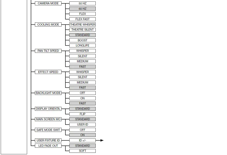
CAMERA MODE – setting the repetition frequency of the LEDs
To avoid flickering during TV recordings, the P9 Beamspot can be adjusted from 50 HZ (PAL, Secam, repetition rate 100Hz) to 60 HZ (NTSC, repetition rate 100Hz) for different camera systems. Flex mode (repetition rate 600Hz is set when using different camera systems or when shooting with mobile phone cameras or similar non-professional cameras. A HighFlex mode is also available. In this mode, the repetition frequencies are set to 3 kHz, which is necessary to ensure smooth movements in dimmed lighting scenes. The factory setting of the P9 Beamspot is 60 Hertz. The changeover is also possible with the light mixing console via the control channel.
COOLING MODE – adjustment of brightness and fan volume
- In the COOLING MODE menu item you can set the fan control and the brightness of the P9 Beamspot. The following settings are available.
- THEATRE WHISPER: volume 29dB(a). In this mode, the spotlight runs at the same brightness up to an ambient temperature of 40°C. It is not necessary to speed up the fans in this mode.
- THEATRE SILENT: from 40°C ambient temperature the spotlight regulates the fans a little up thus remains that the brightness is always the same level.
- STANDARD: from an ambient temperature of approx. 36°C the fans run to cool the LED accord-ingly. The brightness remains constant.
- BOOST: Brightness 15000 lm, the fans run a little stronger in this mode, from approx. 40° ambi-ent temperature the fans run again accordingly.
- LONGLIFE: the fans run a little stronger in this mode, from approx. 40° ambient temperature the fans run again accordingly. We would recommend this mode for permanent installations, as the LED module runs cooler and thus more “stress-free”.
- There is no danger to the life of the device in any mode, as the P9 Beamspot has a temperature safety shutdown. In addition, the LED module is switched off from an ambient temperature of 60°C!
- PAN TILT SPEED – setting pan/tilt speed
In the PAN TILT SPEED menu you can set the maximum speed, the acceleration and thus also the movement volume of the P9 Beamspot. The following setting options are available.- WHISPER: The speed of Pan / Tilt is reduced so much that a volume of 29dB (A) is not exceeded.
SILENT: The speed of Pan / Tilt is slightly faster and thus louder as compared to the Whisper setting.
MEDIUM: The acceleration and deceleration ramps are set very soft so that the headlamp brakes softly and starts.
FAST: The acceleration and deceleration ramps are set very hard so that the headlamp moves very fast and directly at maximum speed.
- WHISPER: The speed of Pan / Tilt is reduced so much that a volume of 29dB (A) is not exceeded.
- EFFECT SPEED – setting effect speed
In the menu item EFFECT SPEED you can set the maximum speed, the effects and thus also the volume of the effects of the P9 Beamspot. The following setting options are available.- WHISPER: The speed of the effects is reduced so much that a volume of 29dB (A) is not exceed-ed.
- SILENT: The speed of the effects is slightly faster and thus a bit louder than with the Whisper setting.
- MEDIUM: The acceleration and deceleration ramps of the effects are set very soft, so that the effects are very soft and thus cause little noise.
- FAST: The acceleration and deceleration ramp effects are set to maximum speed. Very fast gobo and color changes are possible!
- BACKLIGHT MODE – setting the display backlight
This menu item controls the backlight of the display.- OFF: The backlight of the display is always off. The lighting only switches on when a button is pressed. Errors that are indicated by flashing are not displayed in this mode.
- ON: The backlight of the display is always on.
- AUTO: The backlight is switched on / off due to the action.
- DISPLAY ORIENTATION – setting the display orientation
This menu item turns the display orientation. The display can also be rotated when the shortcut ENTER and UP is pressed in the main screen. - MAIN SCREEN MODE – view of the main screen
With this menu item the display of the main screen can be changed. Either the standard (STAND-ARD) screen is displayed with DMX address and DMX mode or the USER FIXTURE ID. This ID is used to number the headlights and to display this number in the display. - SAFE MODE SWITCH – setting of the safe mode switch
This setting can be used to decide whether switching the menu item COOLING MODE can be done directly “OFF” or whether for safety the dimmer and the shutter of the fixture must be closed before switching. -> “ON” - USER FIXTURE ID – adjustment of the user fixture ID
Used to set the USER FIXTURE ID (0-65535). This can be displayed via MAIN SCREEN MODE and serves as an info display of the headlight number. - LED FADE OUT – type of dimming
Used to set how to dim the lower range from 0-5%.- STANDARD: When dimming the headlamp, all LED’s dim out at the same time.
- SOFT: When the headlamp is dimmed, the LED’s are dimmed out in groups (in a row) one row after the other.
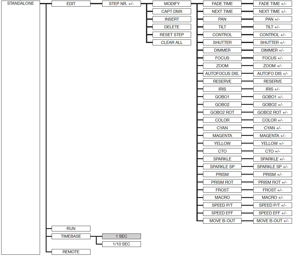
STANDALONE operation
- In standalone operation, up to 20 program steps can be stored in the P9 Beamspot, which can then run in an endless loop. The images can be saved in two ways. Either you program the desired DMX values directly on P9 Beamspot and save them, or you set the DMX values via a connected DMX console and then store them in the P9 Beamspot.
- The menu items MODIFY, RUN and REMOTE can only be called up using a specific key combination. To do this, press and hold “ENTER”, and also press “ESC”.
- Before activating these menu items, remove all other devices in the DMX line that send DMX, e.g. consoles or other spotlights that are not configured as slave devices, as otherwise damage to the DMX drivers may occur.
- Programming the standalone programme on the spotlight display:
- Call up the STANDALONE, EDIT menu item. In the STEP NR+/- menu item, select the desired step and you can change it and its channel parameters in the following menu items: In the MODIFY menu item, set the desired lighting scene and position and determine the individual sequence times of the steps with FADE TIME and NEXT TIME (time for the complete step).
- Use INSERT to insert an additional programming step. The DMX values of the previous step are copied to the new step.
- Use DELETE to delete a step. The display shows STEP NR: 1/X. Use the selection keys to move to the desired step.
- With RESET STEP you reset one step to its default values (DMX 000). The display shows STEP NR: 1/X. Use the selection keys to select your step. CLEAR ALL resets the complete standalone programming steps. Under MODIFY you will find STEP1/1 again. In the STANDALONE, TIMEBASE menu item you have the possibility to change the Fade Time and Next Time from 1 second to 1/10 second.
- Accept the DMX values from an external console:
To accept the DMX values of a connected console, you must first enable the Capture DMX input. To do this, go to the CAPT DMX menu item. The display now shows - CAPTURE DMX 01/01, press the Enter key to switch to START CAPTURE. Now the P9 Beamspot reacts to the signals from the external console.
Launch the standalone program: - Call up the STANDALONE menu and navigate to the RUN submenu. Confirm the selection by pressing the key combination “ENTER” (press and hold) and simultaneously “ESC”. The display then shows: S-ALONE: 01/XX and the program runs in an endless loop.
- Deactivation: Press and hold the “ESC” key and then also press “ENTER”. The menu jumps back one level and RUN appears in the display.
- Operation via master-slave function:
Connect the P9 Beamspot via DMX lines and activate the REMOTE menu item for all slave devices. To do this, navigate in the STANDALONE menu to the REMOTE sub-menu. Activate the REMOTE function by pressing and holding ENTER, and also pressing ESC. The spotlight is in slave mode when the display shows the status REMOTE INACTIVE or REMOTE ACTIVE. REMOTE INACTIVE: The P9 Beamspot is in slave mode but does not receive a DMX signal. - REMOTE ACTIVE: The P9 Beamspot is in slave mode and receives a DMX signal.
The master device is programmed via the MODIFY menu item and started via RUN (press and hold ENTER and also press ESC).
From spotlight software 1.5 the standalone operation can also be programmed via the App we offer.
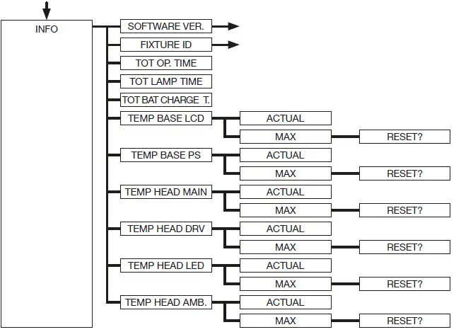
INFO-menu
The Info menu informs you about the respective software, the fixture id, about the total operating time and the different temperatures of the spotlight. The first two menu items in the Info area are the software version and the fixture ID, whereby the software version is an important source of information for our service requests, the fixture ID is less important source of internal information. Under the menu item TOT OPERATE TIME the complete operating time of the headlight is displayed. The menu item TOT LAMP TIME provides information about the pure operating time of the LED module. TOT BAT CHARGE TIME shows the complete charging time of the battery (battery backup).
The TOT OPERATE TIME and the TOT BAT CHARGE TIME can not be deleted! The following temperatures are also displayed:
- TEMP BASE LCD, the temperature on the display board
- TEMP BASE PS, the temperature of the power supply unit
- TEMP HEAD MAIN, the temperature of the head board
- TEMP HEAD DRV, the temperature of the LED driver board
- TEMP HEAD LED, the temperature of the LED module
- TEMP HEAD AMBIENT, the temperature in the head next to the air inlet (ambient temperature)
- Both the current temperature and the maximum temperature are displayed. The maximum temperatures can be individually deleted.
Shortcuts – quick access
- ESC + DOWN
Pressing the ESC and DOWN buttons in the main menu will log the fixture off the programmed Lumen Radio Wireless transmitter. The fixture is now ready to be logged in another transmitter. - ENTER + UP
If ENTER + UP is pressed in the main screen, the screen orientation is rotated by 180 °. - ENTER + ESC
By pressing the ENTER and ESC key, the fixture is locked for user input -> LOCKED. ESC and ENTER release the lock again!
Control options
DMX
Operating modes P9 Beamspot
The P9 Beamspot has 2 different DMX modes. The respective mode can be set in the PERSONALITY, DMX MODE menu item. The set mode is displayed in the main menu.
| Mode 1(M1) | Mode 2 (M2) | |
| Channel 1 | Pan | Pan |
| Channel 2 | Pan fine | Pan fine |
| Channel 3 | Tilt | Tilt |
| Channel 4 | Tilt fine | Tilt fine |
| Channel 5 | Control channel | Control channel |
| Channel 6 | Shutter | Shutter |
| Channel 7 | Dimmer | Dimmer |
| Channel 8 | Focus | Fine dimmer |
| Channel 9 | Zoom | Focus |
| Channel 10 | Autofocus distance | Fine focus |
| Channel 11 | Reserved | Zoom |
| Channel 12 | Iris | Fine zoom |
| Channel 13 | Gobo 1 | Autofocus distance |
| Channel 14 | Gobo 2 | Reserved |
| Channel 15 | Gobo 2 rotation | Iris |
| Channel 16 | Colour wheel | Fine iris |
| Channel 17 | Cyan | Gobo 1 |
| Channel 18 | Magenta | Gobo 2 |
| Channel 19 | Yellow | Gobo 2 rotation |
| Channel 20 | CTO | Gobo 2 fine rotation |
| Channel 21 | Sparkle | Colour wheel |
| Channel 22 | Sparkle speed | Cyan |
| Channel 23 | Prism 1 | Fine cyan |
| Channel 24 | Prism 1 rotation | Magenta |
| Channel 25 | Frost 1 | Fine magenta |
| Channel 26 | Effect macro | Yellow |
| Channel 27 | Pan/tilt speed | Fine yellow |
| Channel 28 | Effect speed | CTO |
| Channel 29 | Blackout Move | CTO fine |
| Channel 30 | Sparkle | |
| Channel 31 | Sparkle speed | |
| Channel 32 | Prism 1 | |
| Channel 33 | Prism 1 rotation | |
| Channel 34 | Prism 1 fine rotation | |
| Channel 35 | Frost 1 | |
| Channel 36 | Effects macro | |
| Channel 37 | Pan/tilt speed | |
| Channel 38 | Effect speed | |
| Channel 39 | Blackout Move |
DMX channel functions P9 Beamspot
| M1 | M2 | M3 | Function | DMX |
| 1 | 1 | Pan (X) movement 546,74° | 000-255 | |
| 2 | 2 | Pan (X) fine (16 Bit) | 000-255 | |
| 3 | 3 | Tilt (Y) movement 281,16° | 000-255 | |
| 4 | 4 | Tilt (Y) fine (16 Bit) | 000-255 | |
| 5 | 5 | Control channel | ||
| To enable uniform dimming manually via faders for all light mixing consoles, 5 diffe- | ||||
| rent settings for the DMX smoothing are available. If the DMX signal is interrupted or | ||||
| too few packets are sent on some DMX consoles, the response of the Sparx 18/30 | ||||
| can be adjusted with this channel. The Minimum DMX Smoothing setting should | ||||
| work on most popular consoles. The values for DMX smoothing must be permanent. | ||||
| For the other values, such as cooling mode, color temperature, zoom modes, camera | ||||
| mode, reset, the values must be applied for 2 seconds, then the device will be per- | ||||
| manently switched (Same setting as in the PERSONALITY menu). | ||||
| Setting for minimal DMX smoothing | ||||
| (A dimmed shutter sequence is possible) | ||||
| Dimmer fade out via fader (fast – slow) | 000-007 | |||
| not used | 008-031 | |||
| Setting for minimum / medium DMX smoothing | ||||
| Dimmer fade out via fader (fast – slow) | 032-039 | |||
| not used | 040-063 | |||
| Setting for medium DMX smoothing | ||||
| Dimmer fade out via fader (fast – slow) | 064-071 | |||
| not used | 072-095 | |||
| Setting for medium / maximum DMX smoothing | ||||
| Dimmer fade out via fader (fast – slow) | 096-103 | |||
| BACKLIGHT MODE – Display backlight configuration | ||||
| AUTO – the fixture controls the backlight automatically | 104-104 | |||
| ON – the backlight is always on | 105-105 | |||
| OFF – the backlight is always off until a key is pressed | 106-106 | |||
| DISPLAY ORIANTATION – display flip or not | ||||
| STANDARD – the display can be read when the headlamp is on a surface | 107-107 | |||
| FLIP – the display orientation is rotated by 180 °, hanging readable | 108-108 | |||
| not used | 109-109 | |||
| MAIN SCREEN MODE – view of the main screen | ||||
| STANDARD – the main screen displays the DMX address, the DMX mode, and when | 110-110 | |||
| wireless is enabled, the field strength. | ||||
| USER FIXTURE ID – the main screen displays the user definable fixture ID / head- | 111-111 | |||
| light number | ||||
| not used | 112-112 | |||
| USER FIXTURE ID SET – Scheinwerfernummer setzen | ||||
| SET – the USER ID can be set. The headlamp takes the 16-bit value of Pan for the | 113-113 | |||
| USER ID | ||||
| not used | 114-127 |
| Setting for maximum DMX smoothing | ||||
| Dimmer fade out via fader (fast – slow) | 128-135 | |||
| DIMMER CURVE – selection of dimmer curve | ||||
| LINEAR – linear dimmer curve | 136-136 | |||
| SQUARE – exponential dimmer curve | 137-137 | |||
| SQUARE INVERSE – exponential inverse dimmer curve | 138-138 | |||
| not used | 139-139 | |||
| RGB/CMY CURVE – selection of RGB/CMY curve | ||||
| SQUARE INVERSE OLD – Exponential inverse old RGB/CMY curve | 140-140 | |||
| LINEAR – linear RGB/CMY curve | 141-141 | |||
| SQUARE INVERSE – Exponential inverse RGB/CMY curve | 142-142 | |||
| FROST CURVE – selection of frost curve | ||||
| LINEAR – linear frost curve | 143-143 | |||
| SQUARE INVERSE – Exponential inverse frost curve | 144-144 | |||
| not used | 145-145 | |||
| PAN/TILT SPEED – selection of PAN/TILT speed | ||||
| WHISPER | 146-146 | |||
| SILENT | 147-147 | |||
| MEDIUM | 148-148 | |||
| FAST | 149-149 | |||
| EFFECT SPEED – selection of effect speed | ||||
| WHISPER | 150-150 | |||
| SILENT | 151-151 | |||
| MEDIUM | 152-152 | |||
| FAST | 153-153 | |||
| LED FADE OUT MODE – selection of dimming out | ||||
| STANDARD | 154-154 | |||
| SOFT | 155-155 | |||
| not used | 156-159 | |||
| COOLING MODE – Adjust the fan volume and brightness | ||||
| This takes place with dimmer / shutter set to closed (DMX 000) then after 2 seconds | ||||
| the fixture will switch this option, except the switch “SAFE MODE SWITCH” in the | ||||
| PERSONALITY menu is set to OFF, then the changeover can take place directly | ||||
| without dimmer and shutter having to be closed. | ||||
| THEATRE WHISPER | 160-160 | |||
| THEATRE SILENT | 161-161 | |||
| STANDARD | 162-162 | |||
| BOOST | 163-163 | |||
| LONGLIFE | 164-164 | |||
| not used | 165-207 | |||
| CAMERA MODE – Setting the LED refresh rate | ||||
| 50Hz | 208-215 | |||
| 60Hz | 216-223 | |||
| FLEX – 600Hz | 224-227 | |||
| High FLEX – 3kHz | 228-231 | |||
| not used | 232-239 | |||
| RESET – a basic reset of the fixture is carried out | ||||
| Reset | 240-247 | |||
| nicht belegt | 248-255 |
| 6 | 6 | Shutter | ||
| Shutter closed | 000-015 | |||
| Shutter open | 016-095 | |||
| Open pulsing shutter >20Hz (rapid – slow) | 096-110 | |||
| Shutter open | 111-111 | |||
| Fade effect with dimmer (slow – rapid) | 112-125 | |||
| Shutter open | 126-126 | |||
| Shutter closed | 127-126 | |||
| Open pulsing shutter <20Hz (rapid – slow) | 128-142 | |||
| Shutter open | 143-143 | |||
| Close pulsing shutter >20Hz (rapid – slow) | 144-158 | |||
| Shutter closed | 159-159 | |||
| Shutter fade, 0% (rapid – slow) | 160-174 | |||
| Shutter open | 175-175 | |||
| Shutter fade, 100% (rapid – slow) | 176-190 | |||
| Shutter closed | 191-191 | |||
| Random shutter 100% (rapid – slow) | 192-206 | |||
| Shutter open | 207-207 | |||
| Random shutter 0% (rapid – slow) | 208-222 | |||
| Shutter closed | 223-223 | |||
| Random shutter fade, 0% (rapid- slow) | 224-238 | |||
| Shutter open | 239-239 | |||
| Random shutter fade, 100% (rapid- slow) | 240-254 | |||
| Shutter open | 255-255 | |||
| 7 | 7 | Dimmer 0 – 100% | 000-255 | |
| 8 | Dimmer fine (16Bit) | 000 | ||
| 8 | 9 | Focus 0-100% | 000-255 | |
| 10 | Focus fine (16 Bit) | 000-255 | ||
| 9 | 11 | Zoom 0 -100% (near 3.4° – far 54°) | 000-255 | |
| 12 | Zoom fine (16 Bit) | 000-255 | ||
| 10 | 13 | Auto focus distance | ||
| Auto focus off | 000-001 | |||
| Auto focus 0 m – 25,5 m (0 =off, DMX / 10 = distance) | 002-255 | |||
| 11 | 14 | Reserved (no function) | 000-255 | |
| 12 | 15 | Iris 0-100% (open -> closed) | 000-255 | |
| 16 | Iris fine (16Bit) | 000-255 | ||
| 13 | 17 | Gobo wheel 1 | ||
| Gobo 0 | 000-007 | |||
| Gobo 1 | 008-015 |

| 13 | 17 | Gobo 2 | 016-023 | |
| Gobo 3 | 024-031 | |||
| Gobo 4 | 032-039 | |||
| Gobo 5 | 040-047 | |||
| Gobo 6 | 048-055 | |||
| Gobo 7 | 056-063 | |||
| Gobo 8 | 064-071 | |||
| Gobo 9 | 072-079 | |||
|
| ||||
| Gobo 10 | 080-087 | |||
| Gobo 11 | 088-191 | |||
| Gobo wheel rotation (fast – slow) | 192-223 | |||
| Gobo wheel rotation (fast – slow) | 224-255 | |||
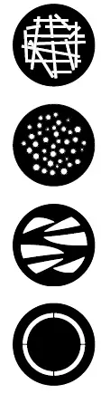
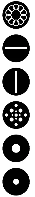
| 15 | 20 | Gobo wheel 2 – rotating gobos 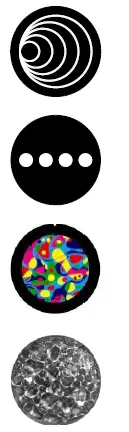 | ||
| Gobo 0 | 000-007 | |||
| Gobo 1 | 008-015 | |||
| Gobo 2 | 016-023 | |||
| Gobo 3 | 024-031 |
| Gobo 4 | 032-039 | |||
| Gobo 5 | 040-047 | |||
|
| ||||
| Gobo 6 | 048-055 | |||
| Gobo 7 | 056-191 | |||
| Gobo wheel rotation (fast – slow) | 192-223 | |||
| Gobo wheel rotation (fast – slow) | 224-255 | |||
| 16 | 21 | Gobo positioning/rotation 2 | ||
| Gobo positioning 0° – 540° | 000-191 | |||
| Gobo rotation, right (rapid – slow) | 192-222 | |||
| Stop gobo rotation | 223-224 | |||
| Gobo rotation, left (slow – rapid) | 225-255 | |||
| 22 | Gobo positioning/rotation 2 fine (16 Bit) | 000-255 | ||
| 19 | 25 | Color wheel White (color shift gobo on) White (color shift gobo off) White/CTB CTB CTB/Red Red Red/Yellow Yellow Yellow/Magenta Magenta Magenta/Green Green Green/Orange Orange Orange/Dark Blue Dark Blue Dark Blue/ Pink Pink Pink/HCRI HCRI HCRI/CTO CTO Linear colours: White – CTB – Red – Yellow – Magenta – Green – Orange – Dark Blue – Pink – HCRI – CTO – White Colour cycle, right (rapid – slow) Colour cycle, left (slow – rapid) | ||
| 000-000 | ||||
| 001-001 | ||||
| 002-003 | ||||
| 004-005 | ||||
| 006-007 | ||||
| 008-009 | ||||
| 010-011 | ||||
| 012-013 | ||||
| 014-015 | ||||
| 016-017 | ||||
| 018-019 | ||||
| 020-021 | ||||
| 022-023 | ||||
| 024-025 | ||||
| 026-027 | ||||
| 028-029 | ||||
| 030-031 | ||||
| 032-033 | ||||
| 034-035 | ||||
| 036-037 | ||||
| 038-039 | ||||
| 040-063 | ||||
| 064-191 | ||||
| 192-223 | ||||
| 224-255 | ||||
| 20 | 26 | Cyan (8 Bit) 0-100% | 000-255 | |
| 27 | Fine cyan (16 Bit) | 000-255 |
| 21 | 28 | Magenta (8 Bit) 0-100% | 000-255 | |
| 29 | Fine magenta (16 Bit) | 000-255 | ||
| 22 | 30 | Yellow (8 Bit) 0-100% | 000-255 | |
| 31 | Fine yellow (16 Bit) | 000-255 | ||
| 23 | 32 | CTO (8 Bit) 0-100% model HP, HC / CTB (8 Bit) 0-100% model WW | 000-255 | |
| 33 | CTO fine (16 Bit) / CTB fine (16 Bit) model WW | 000-255 | ||
| 24 | 34 | Sparkle – Glitter effect Sparkle effect inactive Sparkle effect intensity (minimum – maximum) | 000-000 001-255 | |
| 25 | 35 | Sparkle speed Faded sparkle effect (slow -> rapid) Switched sparkle effect (slow -> rapid) Repetition of the fading and switching blocks | 000-031 032-063 064-255 | |
| 26 | 36 | Prism 1 Open Prism 1 (5-fold linear) | 000-007 008-255 | |
| 27 | 37 | Prism 1 positioning/rotation Prism positioning (0° – 540°) Prism rotation, right (rapid -> slow) Stop prism rotation Prism rotation, left (slow -> rapid) | 000-191 192-222 223-224 225-255 | |
| 38 | Prism 1 fine positioning/rotation (16 Bit) | 000-255 | ||
| 30 | 42 | Frost 1 Frost 0-100% | 000-255 | |
| 32 | 44 | Effects macro Macro inactive Macro 001 – Macro 255 | 000-000 001-255 | |
| 33 | 45 | Pan/tilt speed Real-time motion Delayed motion (rapid – slow) | 000-003 004-255 | |
| 34 | 46 | Effects speed Real-time effects Delayed effects (rapid – slow) | 000-003 004-255 | |
| 35 | 47 | Blackout Move Not assigned Blackout during pan/tilt Blackout during Gobo, Colour, Prism, CMY, Iris, Frost Blackout during Gobo, Colour, Prism, CMY, Iris, Frost, Zoom, Focus Blackout during Gobo, Colour, Prism, CMY, Iris, Frost, Pan/Tilt Blackout during Gobo, Colour, Prism, CMY, Iris, Frost, Zoom, Focus, Pan/Tilt | 000-095 096-127 128-159 160-191 192-223 224-255 |
Control channel
Via the control channel different functions of the fixture can be switched. The following functions can be switched via the control channel. Response of the headlamp when dimming via faders
- BACKLIGHT MODE – display backlight
- DISPLAY ORIENTATION – display orientation
- MAIN SCREEN MODE – main screen view
- USER FIXTURE ID SET – set headlight number
- DIMMER CURVE – dimmer curve adjustment
- FROST CURVE – setting the frost curve
- PAN / TILT SPEED – pan / tilt speed
- EFFECT SPEED – effect speed
- LED FADE OUT MODE – type of dimming
- COOLING MODE – adjust the fan volume and brightness
- CAMERA MODE – sets the LED refresh rate
- RESET – a basic reset of the headlight is performed
- For details, see DMX Channel Functions for the P9 Beamspot on page 24.
Sparkle effect, sparkle speed
Animation effects can be created via this channel in connection with the focus. Depending on the intensity, the projection can be made to shake more or less. This effect can be dimmed or switched.
Auto focus
To activate the autofocus function, set the autofocus distance channel to around 50%. Then best use gobo wheel 2 for fine adjustment of the system and set the focus accordingly to 125 (32000): Then set the distance to the headlight by focusing the headlight using the autofocus distance. As a guideline, DMX value divided by 10 corresponds to the distance (DMX 100/10 distance = 10m). Now the headlight can be operated with autofocus via the zoom. Using the following table, the focus values for the individual effects can now be preselected and zoomed in with autofocus
| Gobo1 | Gobo2 Open | Iris | |
| Focus 8Bit | 95 | 125 | 215 |
| Focus 16Bit | 24320 | 32000 | 55040 |
Artnet
The spotlight can be controlled via Artnet – ArtNET 4. To do this, set the Artnet address via the menu item DMX / NET ADDR -> ARTNET ADDRESS and also select it via the menu item PERSONALITY -> DMX INPUT CONFIG -> NETWORK -> MODE -> ARTNET. In addition, define the IP address of the spotlight via PERSONALITY -> DMX INPUT CONFIG -> NETWORK -> IP ADDRESS. Further details and setting options can be found on page 18
Streaming ACN
The headlight can be controlled via sACN – Streaming ACN. To do this, set the sACN address via the menu item DMX / NET ADDR -> SACN ADDRESS and also select it via the menu item PERSONALITY -> DMX INPUT CONFIG -> NETWORK -> MODE -> SACN. In addition, define the IP address of the spotlight via PERSONALITY -> DMX INPUT CONFIG -> NETWORK -> IP ADDRESS. Further details and setting options can be found on page 18
Wireless-DMX
The P9 Beamspot is equipped with a Lumen Radio CRMX receiver for wireless DMX. The receiver can process both DMX and RDM. If there is a cable and wireless connection to the P9 Beamspot, the cable connection has priority! The received signal can be output via the DMX connection.
To do this, set the DMX OUTPUT CONFIG setting to ON in the PERSONALITY menu. After confirming with ENTER, the spotlight will output the entire universe received via wireless DMX.
RDM
The P9 Beamspot can communicate via RDM (Remote Device Management) in accordance with ESTA American National Standard E1.20-2006. RDM is a bidirectional communication protocol for use in DMX512 control systems. It is the open standard for the configuration and status monitoring of DMX-512 devices. The RDM protocol enables data packets to be inserted into a DMX-512 data stream without affecting existing non-RDM devices. It enables a console or dedicated RDM controller to send commands to specific devices and receive messages. The P18 can send and receive RDM via DMX and Artnet 4. The spotlight is also designed to send RDM via sACN and receive it via Artnet. The RDM functionality depends on the lighting control desk used, the operating instructions of the respective desk manufacturer must also be observed
RDM-UID
Every P9 Beamspot has a factory-set RDM-UID (unique identification number), which makes it addressable and identifiable in RDM systems
RDM-PIDs
The P9 Beamspot supports the RDM PIDs (parameter IDs) required by ESTA as well as manufacturer- specific PIDs.
Standard RDM parameter IDs
| RDM parameter ID | GET | SET | DISCO- VERY | Note |
| RDM identification | ||||
| DISC_UNIQUE_BRANCH | ✔ | is used for fixture identification | ||
| DISC_MUTE | ✔ | is used for fixture identification | ||
| DISC_UN_MUTE | ✔ | is used for fixture identification | ||
| RDM status determination | ||||
| QUEUED_MESSAGE | ✔ | |||
| STATUS_MESSAGES | ✔ | |||
| STATUS_ID_DESCRIPTION | ✔ | |||
| CLEAR_STATUS_ID | ✔ | |||
| RDM information | ||||
| SUPPORTED_PARAMETERS | ✔ | |||
| RDM configuration | ||||
| DEVICE_MODEL_DESCRIPTION | ✔ | |||
| MANUFACTURER_LABEL | ✔ | |||
| FACTORY_DEFAULTS | ✔ | |||
| SOFTWARE_VERSION_LABEL | ✔ | |||
| DMX_PERSONALITY | ✔ | |||
| DMX_PERSONALITY_DESCRIPTION | ✔ | |||
| DMX_START_ADDRESS | ✔ | |||
| SENSOR_DEFINITION | ✔ | |||
| DEVICE_HOURS | ✔ | |||
| LAMP_HOURS | ✔ | |||
| IDENTIFY_DEVICE | ✔ | |||
| RESET_DEVICE | ✔ | |||
| PERFORM_SELFTEST | ✔ | |||
| SELFTEST_DESCRIPTION | ✔ | |||
Manufacturer specific RDM parameter IDs
| RDM parameter ID | GET | SET | DISCO- VERY | Note |
| RDM configuration | ||||
| Battery Charge Hours | ✔ | |||
| Error Number | ✔ | |||
| Error | ✔ | |||
| Select Next Error | ✔ | |||
| Remove Error | ✔ | |||
| Remove New Error Flag | ✔ | |||
| User Defaults | ✔ | |||
| User Fixture ID | ✔ | |||
| Fixture Lock On/Off | ✔ | ✔ | ||
| Dimmer Curve | ✔ | ✔ | ||
| RGB Curve | ✔ | ✔ | ||
| Frost Curve | ✔ | ✔ | ||
| Camera Mode | ✔ | ✔ | ||
| Cooling Mode | ✔ | ✔ | ||
| Pan Tilt Speed | ✔ | ✔ | ||
| Effect Speed | ✔ | ✔ | ||
| Backlight Mode | ✔ | ✔ | ||
| Disp Orientation | ✔ | ✔ | ||
| Main Screen Mode | ✔ | ✔ | ||
| Safe Mode Switch | ✔ | ✔ | ||
| LED Fade Out Mode | ✔ | ✔ |
RDM sensor IDs
| RDM sensor ID | GET | SET | DISCO- VERY | Note |
| RDM sensors | ||||
| Temp Sens Base LCD | ✔ | ✔ | ||
| Temp Sens Base PS | ✔ | ✔ | ||
| Temp Sens Head PCB | ✔ | ✔ | ||
| Temp Sens Head Drv | ✔ | ✔ | ||
| Temp Sens Head LED | ✔ | ✔ | ||
| Temp Sens Head Air | ✔ | ✔ | ||
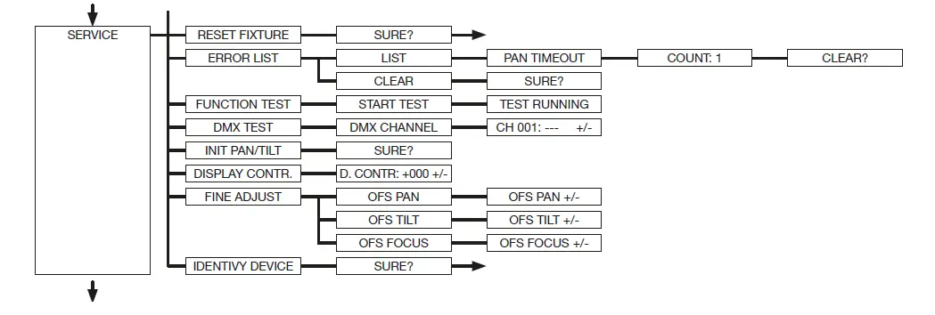
Service
Service menu
- RESET FIXTURE
Upon the “Reset” command, P9 Beamspot will initialise to its initial values. It is the same procedure as after switching on the P9 Beamspot. If an error message appears in the display, this could be the first step to correct it. - ERROR LIST
The P9 Beamspot stores all occurring errors internally. An error message can have a harmless cause. If you experience frequent error messages, please contact your dealer or the JB-Lighting service department. All error messages are displayed with the respective frequency and can be deleted. - FUNCTION TEST
This function allows you to test all functions of the P9 Beamspot without using a light mixer. The pan/tilt reset is deactivated in the process. - DMX TEST
This menu item is used to test the DMX input. Use the function keys to select the DMX channel to be tested. The display shows the incoming value, at the same time the P9 Beamspot reacts accordingly. - INIT PAN TILT
The P9 Beamspot is calibrated in the pan/tilt position at the factory. If it loses this calibration, i.e. it strikes against the stop or no longer finds its position, it can be re-initialised using this function. This process takes about 3-4 minutes and ends with a reset of the spotlight. - DISPLAY CONTRAST
The contrast of the LCD display may change when the temperature is too high. In this menu item the contrast can be adjusted. - FINE ADJUST
The FINE ADJUST area is protected by a key combination. Focus, shapers, shaper rotation, pan and tilt are calibrated at the factory. If there are large deviations in the calibration between the individual headlights, this can be corrected in the FINE ADJUST menu. For more information please contact our service. - IDENTIFY DEVICE
The RDM command IDENTIFY DEVICE can be called up or deactivated via this menu item.
Changing gobo
WARNING: Disconnect fixture before opening!
To open the device (from the right side) place the spotlight on a firm base as shown in the picture, the display (1) facing you, the tilt lock (2) is on the right side and the spotlight head facing away from you (3) (Or look through the grille into the spotlight from behind and find a closed honeycomb showing the cover to be opened). To lift off the cover, open the four camlocks by half a turn, lift off the cover and unhook the safety lanyard. Now open the two knurled screws (4) and remove the gobo insert. The following figure (1) shows the gobo insert of the P9 Beamspot. Check that the focus is moved direction to the front lense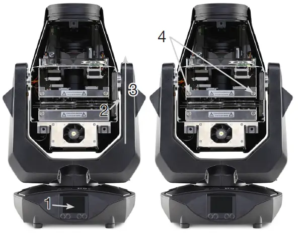
To change the rotating gobos remove only the clamping ring (A) with a pointed object replace the gobo and then put the clamping ring again. When installing glass gobos, make sure the white coated side faces the front lens. Gobos that are not allowed to twist, e.g. Logos are additionally recommended to be secured against twisting with a drop of silicone adhesive.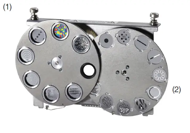
When inserting original gobos, pay attention to the markings on the gobo, the gobo holder and the gobo wheel!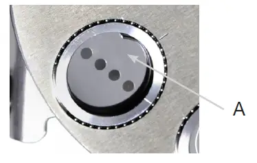
Gobo size
If you want to have your own gobos produced, please note the following dimensions: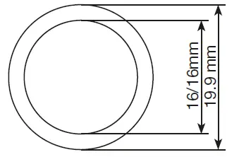
- Usable diameter, rotating gobowheel 1: 16.00 mm
- Usable diameter, rotating gobowheel 2: 16.00mm
- Outer diameter: 19.90 mm (+0/-0.1 mm)
- Maximum thickness: 1.1 mm
Software update
The P9 Beamspot can be updated via a USB stick with micro-USB connection. To do this, copy the file directly into the root directory of the USB stick. Then press and hold the right key below the display, switch on the power of the P9 Beamspot as soon as the message Insert USB stick appears on the display release the key. Now plug in the USB stick on the back of the device below the signal connections and follow the instructions on the display. The P9 Beamspot com-pletes the software update with a reset. You will find the latest software on our homepage.
Testing of electrical equipment
According to the German Social Accident Insurance (DGUV) Regulation 3 / Regulation 4, electrical systems and equipment must be subjected to regular inspections. The fixing screw of the DMX 5-pin socket can be used as measuring point for insulation and residual current measurement. The screw is connected to all sheet metal parts via a contact washer.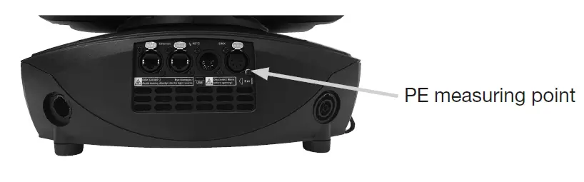
Cleaning the device
You should check the function of the fans in the head and foot at regular intervals. Above all, make sure that the air intakes and the interior of the P9 Beamspot are free of fluff and dust. To do this, open the head cover (4x camlocks with half a turn) and the base plate on the foot. You can clean the P9 Beamspot with a brush and a vacuum cleaner. In addition, you can remove the gobo insert (1) and the shutter slide insert (2) by loosening the knurled screws (3) and sliding the focus carriage towards the lens. Then you can clean the colour filters, glass gobos and CMY panes with a soft cloth and a little window cleaner. To clean the frost flaps, prisms and zoom/focus unit, remove the four Phillips screws (4) and then the cover. Ensure that you do not bend or damage any parts during cleaning. When cleaning is complete, reconnect the flap, replace the Phillips screws (4) and return the inserts to the unit.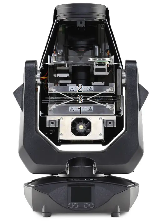
Service and maintenance
- On the P9 Beamspot, the zoom / focus guide rails and the rotating gobos should be checked for sufficient lubrication at regular intervals – once a year. To do this, open the head cover (4x camlocks with half a turn), the zoom cover (3 Phillips screws) see (4) and remove the gobo insert (2 knurled screws).
- Please note that the rotating gobos and the guide rails do not run dry; if necessary, the rotating gobos must be oiled with a special syringe and the guide rails with a brush with our special sil-icone oil.
- After the gobos and the rails have been checked or oiled, reinsert the slot and close the zoom cover again. After completing the work, replace the head cover on the headlight and test all the functions of the headlight.
Specifications
- Dimensions and weight
- Length ……………………………………………………….265 mm
- Width ………………………………………………………..398 mm
- Height ……………………………………………………….609 mm
- Net weight ……………………………………………………… 17 kg
- Electronic system
- Mains connection …………………………………… 100-240 V AC, 50-60Hz
- Maximum power consumption ……………………………………….460 VA
- Power consumption in standby ……………………………………….100 VA
- Temperature
- Maximum ambient temperature ……………………………………….45 °C
- Minimum ambient temperature …………………………………………5 °C
- Optics, Photometric Data
- Light source …………………………………… White light LED module 330W
- Luminous intensity HP …………………………………. 25000 Lumen @ 20°C
- Effects
- Pan ………………………………………………………… 546.74°
- Tilt …………………………………………………………. 281.16°
- Zoom ……………………………………………………….3.4° – 54°
- Construction
- Colour ………………………………………………………… black
- Housing ………………………………………………………PC ABS
- Protection class ………………………………………………….. IP 20
- Plug-in technology ………………………………………………….yes
- Installation
- Installation site …………………………………………………. indoors
- Holder ……………………………………………….2x Omega brackets
- Position ………………………………………………………….any
- Minimum fixture distance to flammable objects …………………………….0.5 m
- Minimum distance between the light emission and the surface to be illuminated ……..2,0 m
- Connections
- Power input ……………………………………… Neutrik power
- CON TRUE1 Power feed-through ……………………………….. Neutrik power
- CON TRUE1 DMX/RDM in/out USITT DMX512 ………………………………5-pin, in/out
- XLR Ethernet in/out ………………………………………….. Neutrik ether
- CON Micro-USB ……………………………………………… Software update
Declaration of Conformity
Declaration of Conformity in the sense of the Directive: 2014/35/EU Low Voltage Directive,
(Directive 2014/35/EU of the European Parliament and of the Council of 26/02/2014 to approximate the laws of the Member States relating to electrical equipment designed
for use within certain voltage limits) in the sense of the Directive: 2014/30/EU Electromagnetic compatibility
(Directive 2014/30/EU of the European Parliament and of the Council of 26/02/2014 to approximate the laws of the Member States relating to electromagnetic compatibility)
The manufacturer,
JB-Lighting Lichtanlagentechnik GmbH Sallersteigweg 15 89134 Blaustein-Wippingen
declares that the product: P9
complies with the essential protection requirements of the directives. The following standards were used for conformity assessment:
Emissions requirements per EN 55032:2015 Information technology equipment, radio interference characteristics – Limit values and measuring methods – Limit value class A
Conducted interference EN 55032:2015 emission requirements for information technology equipment, radio interference characteristics – Limit values and measuring methods – Limit value class A
Radiation Information EN 55032:2015 technology equipment, radio interference characteristics – Limit values and measuring methods – Limit value class A
Harmonic currents EN 61000-3-2:2015 Electromagnetic compatibility Part 3-2: Limits, testing of harmonic currents (for devices with an input current < 16A per phase)
Flicker EN 61000-3-3:2013 Electromagnetic compatibility (EMC) Part 3-3: Limits, limitation of voltage changes,
Voltage fluctuations and flicker in low-voltage networks (for devices with an input current < 16A per phase)
Immunity – requirements per EN 61000-6-2:2005 Electromagnetic compatibility (EMC) – Part 6-2: Generic standard – Immunity in industrial areas
- EN 61000-4-2:2009 Part 4-2: Immunity to static electricity discharge
- EN 61000-4-3:2006 +A1:2008 +A2:2010 Part 4-3: Immunity to high-frequency electromagnetic fields
- EN 61000-4-4:2012 Part 4-4: Immunity against fast transient electrical disturbances (burst)
- EN 61000-4-5:2006 Part 4-5: Interference voltages against surge voltages
- EN 61000-4-6:2014 Part 4-6: Immunity to conducted disturbances, induced by HF
- EN 61000-4-8:2010 Part 4-8: Immunity to magnetic fields with power technology frequencies
- EN 61000-4-11:2004 Part 4-11: Immunity against voltage dips, short-term interruptions and voltage fluctuations
Blaustein, 01/09/2021 Jürgen Braungardt CEO
JB-Lighting Lichtanlagentechnik GmbH Sallersteig 15 89134 Blaustein
Tel. +49 7304 9617-0
Fax. +49 7304 9617-99
[email protected]
www.jb-lighting.de


