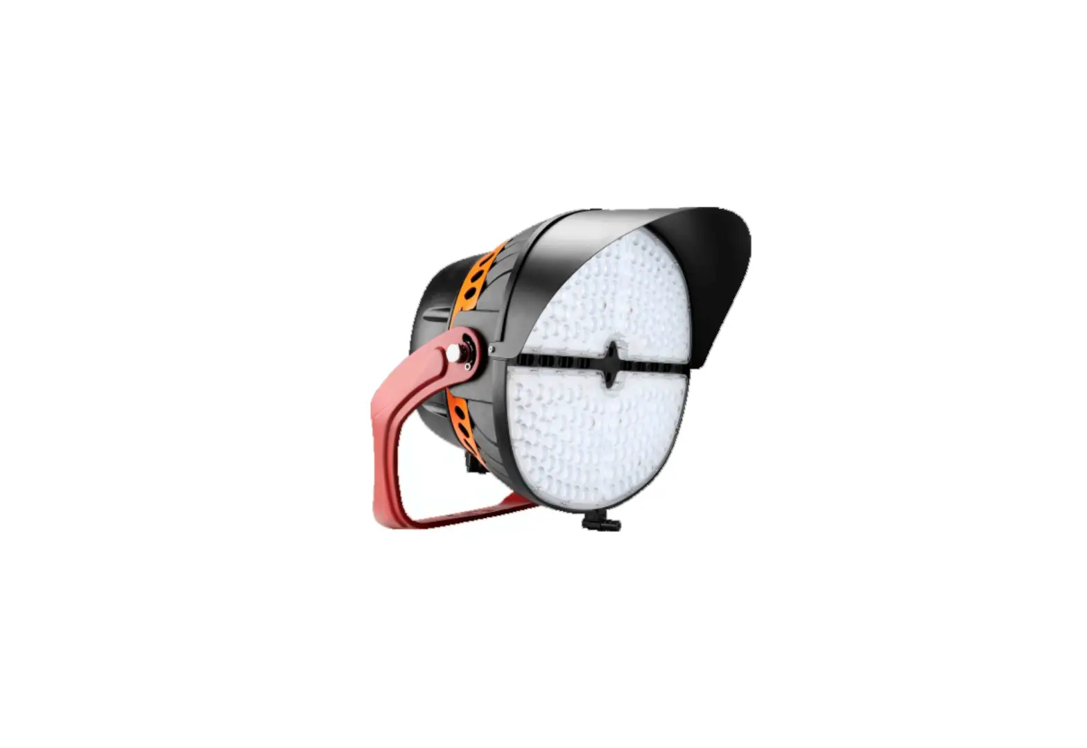
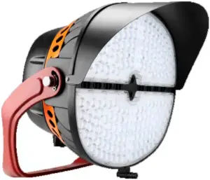
JADEMAR JSLP-ME LED Sports Lighting
INSTALLATION INSTRUCTIONS
![]() WARNING
WARNING
PLEASE READ ALL INSTRUCTIONS BEFORE ATTEMPTING INSTALLATION
- All electrical work must conform to the National Electric Code (NEC) and all applicable local codes and ordinances.
- Only qualified personnel shall install and maintain the luminaires. Jademar recommends that a licensed electrician install and maintain the luminaire. Verify the safety of existing power distribution system before beginning installation. Failure to follow Operating Instructions may lead to death, Severe Injury, or Property Damage.
- Fixtures must be grounded and installed in accordance with the National Electrical Code and all local codes. If you are not sure if your power system is grounded, DO NOT install the luminaire. Contact a licensed electrician for information on proper grounding methods as required by the electrical code. FAILURE TO FOLLOW THIS WARNING MAY LEAD TO DEATH, SEVERE INJURY, OR PROPERTY DAMAGE.
- Turn off power and allow to cool before performing any electrical or control work. FAILURE TO FOLLOW THIS WARNING MAY LEAD TO DEATH, SEVERE INJURY, OR PROPERTY DAMAGE.
- DO NOT make or alter any open holes in the luminaire. Do not modify the luminaire.
- Risk of eye injury! Eye protection is required at all times during the installation, operation, and maintenance of the luminaire. The high intensity light produced by the luminaire can cause severe damage to the eye if viewed directly at close range. Avoid being in front of a luminaire that is on or wear suitable light blocking protective eyewear such as welding goggles. The luminaire should be positioned so that prolonged staring into the luminaire at a distance closer than 10m is not expected.
- NEVER point the aiming laser at any person or animal as it can cause permanent damage to eyes. Use laser only for aiming fixtures as directed.
- CAUTION – RISK OF FIRE.
- This product is not available for several special environments, such as places with corrosive gas liquids or high pressure water vapor.
- This luminaire is designed to operate in ambient temperatures ranging from -40C to 55C (-40F to 131F).
CAUTION WHEN USING THE LASER AIMING ASSEMBLY Never look directly into the laser beam.
 Never look directly into the laser beam.
Installation Guide 1 (Default)
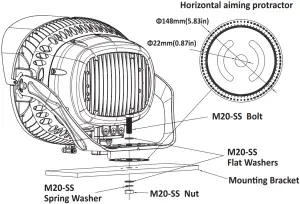
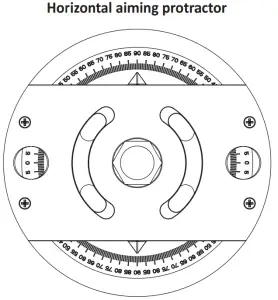
- Align the center hole of the horizontal aiming protractor and the mounting bracket and a ach the horizontal aiming protractor to the bracket.
- Secure visor on fixture with three PM5*8-SS screws (30-45 in-lbf (3.5 to 5 N-m)).
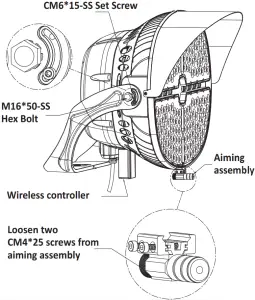
- Loosen two CM4*25 screws from aiming assembly; a ach the aiming assembly in the keyhole slots and ghten two screws (30-45 in-lbf (3.5 to 5 N-m)).
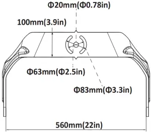
- Drill appropriate knockout according to the size of the moun ng bracket.
- Set luminaire in place and install bolt, flat washers, spring washer and nut to securely fasten the fixture mounting bracket to the moun ng structure (35-45 -lbf(47 to 60 N-m)). Do not fully ghten the hardware un l the fixture is aiming, just make sure the fixture is secure.
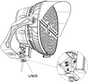
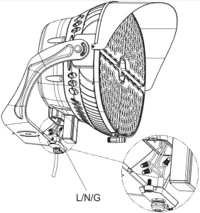
- Remove one of the 1/2″ screw plugs from the bo om of the junc on box, then remove the junction box bottom cover, pass the input wire through the bottom cover (sufficiently long wire needed) and secure it with a metal waterproof connector (supplied by others).
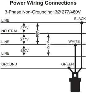
- Make all necessary wiring connec ons, according to below wiring diagram, observing proper voltage and polarity.
- Make sure that all wires are securely connected and that there are no exposed conductors, carefully push the wire into the junc on box (Make sure wires do not get pinched), then reinstall the junc on box bo om cover (35-75 inlbf (4-8 N-m)).
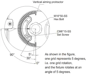
- Slightly loosen the fixture aiming screws just enough to allow the fixture to rotate and lt. Use horizontal aiming protractor and aiming sights to locate fixtures depending on different lighting needs.
- After aiming is complete, tighten all bolts and screws including hex bolts (26-33 -lbf (35 to 45 N-m)) and set screws (35-75 in-lbs (4-8 N-m)) on side of fixture and mounting hardware.
- Installation and service of luminaires should be performed by a qualified licensed electrician.
Installation Guide 2 (Option)
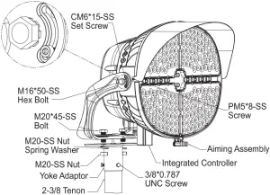
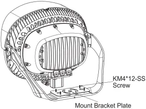
- Secure the mount bracket plate on the mounting bracket with four KM4*12-SS screws (30-45 in-lbf (3.5 to 5 N-m)).
Note: The first step is only for small size; the mount bracket plate for large size has been pre-installed at the factory. - Secure visor on fixture with three PM5*8-SS screws (30-45 in-lbf (3.5 to 5 N-m)).
- Secure the yoke adaptor on the mounting bracket with two bolts, spring washers and nuts (35-45 -lbf(47 to 60 N-m)), then snap the pole into the into the 2-3/8 tenon, and lock it with the three 3/8 x 0.787 screws (10-15 -lbf (14 to 18 N-m)).
- Remove one of the 1/2″ screw plugs from the bottom of the junction box, then remove the junction box bottom cover, pass the input wire through the bottom cover (sufficiently long wire needed) and secure it with a metal waterproof connector (supplied by others).
- Make all necessary wiring connections, according to below wiring diagram, observing proper voltage and polarity.
- Make sure that all wires are securely connected and that there are no exposed conductors, carefully push the wire into the junction box.(Make sure wires do not get pinched), then reinstall the junction box bo om cover (35-75 in-lbs (4-8 N-m)).
- Slightly loosen the fixture aiming screws just enough to allow the fixture to rotate and tilt. Turn on the laser and using aiming assembly to aim the fixture to the proper point may according to the lighting design.
- A er aiming is complete, tighten all bolts and screws including hex bolts (26-33 -lbf (35 to 45 N-m)) and set screws (35-75 in-lbs (4-8 N-m)) on side of fixture and mounting hardware.
Integrated Controller Installation (Option)
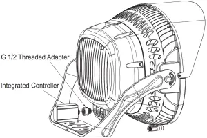
- Remove the bo om cover of the junction box and the screw plug on the le side of the junction box.
- Pass the smart controller’s power cord through the G 1/2 threaded adapter and then screw the smart controller into the adapter.
- Push the wire into the junc on box and screw the connected controller and threaded adapter into the entire fixture
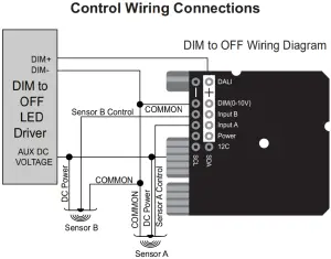
- Make all necessary wiring connec ons, according to below wiring diagram, observing proper voltage and polarity. Make sure that all wires are securely connected and that there are no exposed conductors
- Carefully push the wire into the junc on box, Make sure wires do not get pinched, then reinstall the junction box bo om cover (35-75 in-lbs (4-8 N-m)).

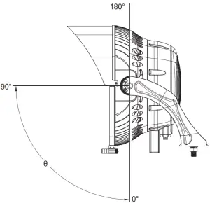
Orient Tilt
The Orient angle refers to the direc on of the fixture face in the Z plane. In other words, mount the fixture on the structure, but keep the mounting nut slightly loosened so that the en re fixture to spin about the mounting bolt. Set the luminaire Orient by rotating the fixture moun ng bracket rela ve to the mounting structure.
Tilt angle refers to the direc on in which the fixture faces in the Y plane. When the luminaire is securely mounted on the structure so that the mounting bracket does not move, but the side hexagon and the mounting screw are loosened, the fixture may rotate upward in the mounting bracket. Set the lt angle of the fixture by rotating the fixture housing relative to the fixture mounting bracket.
Electrical Connections
Note:
- For replacement LED Assemblies and Drivers please contact MESTER Lighng for any replacement parts.
- Contact your local distributor or agent to confirm parts availability prior to ordering replacement parts.
Accessories List
Diagram | Quantity | |
| Battery |  | 3 pcs |
| Laser aiming assembly | 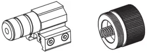 | 1 set (Two parts, aiming head and cover) |
| Hexagon key | 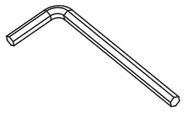 | 2 pcs |
| PM5*8 screws | 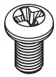 | 3 pcs |
| HM20*60-SS Bolt | 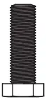 | 1 pc |
| M20-SS Flat Washers | 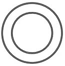 | 2 pcs |
| M20-SS Spring Washer | 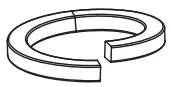 | 1 pc |
| M20-SS Nut | 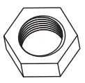 | 1 pc |
| Visor | 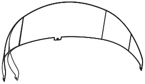 | 1 pc |
| Horizontal aiming protractor |  | 1 pc |
Miami, FL USA – [email protected]
T: 305.640.0465
F: 305.640.0468
WWW.JADEMAR.COM