CVTE SKO.W603.5 2T2R USB Wi-Fi Module
Introduction
SKO.W603.5 module is based on the MediaTek MT7603U solution. The MT7603U is a highly integrated Wi-Fi single chip that supports a 300 Mbps PHY rate. It fully complies with IEEE 802.11n and IEEE 802.11 b/g standards, offering feature-rich wireless connectivity at high standards, and delivering reliable, cost-effective throughput from an extended distance. This documentation describes the engineering requirements specification
FEATURES
| Reserving System
| IEEE Std. 802.11b |
| IEEE Std. 802.11g | |
| IEEE Std. 802.11n | |
| Chip Solution
| MT7603U |
| Band
| 2.4GHz |
| Dimensions
| 45.0mm*30.0mm*3.4mm |
| Model
| Installation Mode
| Radio Technology
| Operation Frequency
| Antenna Port
| Remark
|
| SKO.W603.5 |
Ext-WIFI | IEEE 802.11b/g/n | 2.4GHz | PCB On-board PCB Antenna | 45.0mm*30.0m m*3.4mm |
Block Diagram
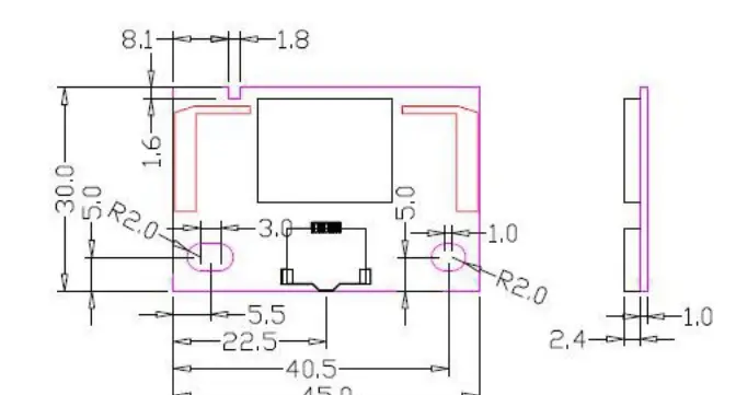
Package Outline and Mounting
Pin Definition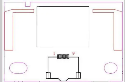
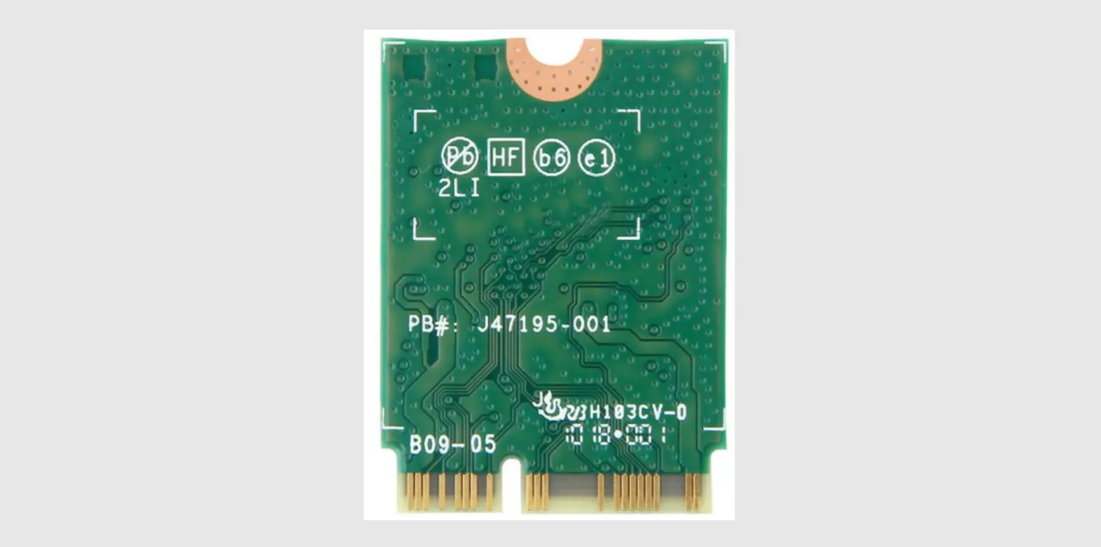
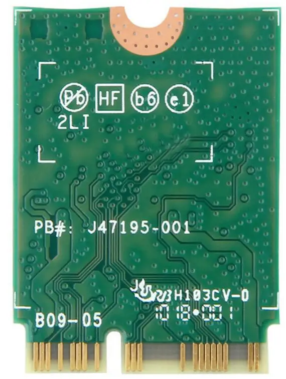
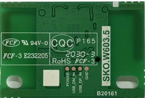
Product Pictures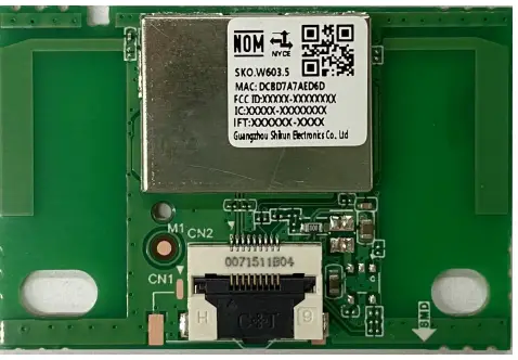
Materials BOM
| Número | Componentes clave | Modelo | Especificaciones | Observación |
| 1 | Circuito integrado | MT7603U | 48-QFN | — |
| 2 | PCB | SKO.W603.5 | FR-4,2LAY | — |
| 3 | Oscilador de cristal | 2.3.3.400001208 | 40MHz | — |
General Requirements
| No. | Feature | Description |
| 8-1 | Operation Voltage | 3.3V±0.3V |
| 8-2 | Current Consumption | 430mA |
| 8-3 | Ripple | ≤100mV |
| 8-4 | Operation Temperature 工 | 0°C to +40°C |
| 8-5 | Antenna Type | Internal antenna |
| 8-6 | USB | High Speed USB 2.0 Interface |
| 8-7 | Storage Temperature | -40°C to +85°C |
Electrical Characteristics
IEEE 802.11b Section
| Items | Contents | ||||
| Specification | IEEE802.11b | ||||
| Mode | CCK | ||||
| Channel | CH1 to CH13 | ||||
| Data rate | 1, 2, 5.5, 11Mbps | ||||
| TX Characteristics | Min. | Typ. | Max. | Unit | Remark |
| 1. Power Levels(Calibrated) | |||||
| 1) For Each antenna port | 14 | 16 | 18 | dBm | |
| 2. Spectrum Mask @ target power | |||||
| 1) fc +/-11MHz to +/-22MHz | – | – | -30 | dBr | |
| 2) fc > +/-22MHz | – | – | -50 | dBr | |
| 3 Constellation Error(EVM)@ target power | |||||
| 1) 1Mbps | – | – | -10 | dB | |
| 2) 2Mbps | – | – | -10 | dB | |
| 3) 5.5Mbps | – | – | -10 | dB | |
| 4) 11Mbps | – | – | -10 | dB | |
| 4. Frequency Error | -20 | – | 20 | ppm | |
| RX Characteristics | Min. | Typ. | Max. | Unit | |
| 5 Minimum Input Level Sensitivity (each chain) | |||||
| 1) 1Mbps (FER ≦8%) | – | – | -83 | dBm | |
| 2) 2Mbps (FER ≦8%) | – | – | -80 | dBm | |
| 3) 5.5Mbps (FER ≦8%) | – | – | -79 | dBm | |
| 4) 11Mbps (FER ≦8%) | – | – | -76 | dBm | |
| 6 Maximum Input Level (FER ≦8%) | -10 | – | – | dBm | |
IEEE 802.11g Section
| Items | Contents | ||||
| Specification | IEEE802.11g | ||||
| Mode | OFDM | ||||
| Channel | CH1 to CH13 | ||||
| Data rate | 6, 9, 12, 18, 24, 36, 48, 54Mbps | ||||
| TX Characteristics | Min. | Typ. | Max. | Unit | Remark |
| 1. Power Levels | |||||
| 1) For Each antenna port | 12 | 14 | 16 | dBm | |
| 2. Spectrum Mask @ target power | |||||
| 1) at fc +/-11MHz | – | – | -20 | dBr | |
| 2) at fc +/-20MHz | – | – | -28 | dBr | |
| 3) at fc > +/-30MHz | – | – | -40 | dBr | |
| 3 Constellation Error(EVM)@ target power | |||||
| 1) 6Mbps | – | – | -5 | dB | |
| 2) 9Mbps | – | – | -8 | dB | |
| 3) 12Mbps | – | – | -10 | dB | |
| 4) 18Mbps | – | – | -13 | dB | |
| 5) 24Mbps | – | – | -16 | dB | |
| 6) 36Mbps | – | – | -19 | dB | |
| 7) 48Mbps | – | – | -22 | dB | |
| 8) 54Mbps | – | – | -25 | dB | |
| 4 Frequency Error | -20 | – | 20 | ppm | |
| RX Characteristics | Min. | Typ. | Max. | Unit | |
| 5 Minimum Input Level Sensitivity (each chain) | |||||
| 1) 6Mbps (PER ≦10%) | – | – | -85 | dBm | |
| 2) 9Mbps (PER ≦10%) | – | – | -84 | dBm | |
| 3) 12Mbps (PER ≦10%) | – | – | -82 | dBm | |
| 4) 18Mbps (PER ≦10%) | – | – | -80 | dBm | |
| 5) 24Mbps (PER ≦10%) | – | – | -77 | dBm | |
| 6) 36Mbps (PER ≦10%) | – | – | -73 | dBm | |
| 7) 48Mbps (PER ≦10%) | – | – | -69 | dBm | |
| 8) 54Mbps (PER ≦10%) | – | – | -65 | dBm | |
| 6 Maximum Input Level (PER ≦10%) | -20 | – | – | dBm |
IEEE 802.11n HT20 Section
| Items | Contents | ||||
| Specification | IEEE802.11n HT20 @ 2.4GHz | ||||
| Mode | OFDM | ||||
| Channel | CH1 to CH13 | ||||
| Data rate (MCS index) | MCS0/1/2/3/4/5/6/7 | ||||
| TX Characteristics | Min. | Typ. | Max. | Unit | |
| 2. Power Levels | |||||
| 1) For Each antenna port | 11 | 13 | 15 | dBm | |
| 3. Spectrum Mask @ target power | |||||
| 1) at fc +/-11MHz | – | – | -20 | dBr | |
| 2) at fc +/-20MHz | – | – | -28 | dBr | |
| 3) at fc > +/-30MHz | – | – | -45 | dBr | |
| 4. Constellation Error(EVM)@ target power | |||||
| 1) MCS0 | – | – | -5 | dB | |
| 2) MCS1 | – | – | -10 | dB | |
| 3) MCS2 | – | – | -13 | dB | |
| 4) MCS3 | – | – | -16 | dB | |
| 5) MCS4 | – | – | -19 | dB | |
| 6) MCS5 | – | – | -22 | dB | |
| 7) MCS6 | – | – | -25 | dB | |
| 8) MCS7 | – | – | -28 | dB | |
| 5. Frequency Error | -20 | – | 20 | ppm | |
| RX Characteristics | Min. | Typ. | Max. | Unit | |
| 6. Minimum Input Level Sensitivity (each chain) | |||||
| 1) MCS0 (PER ≦10%) | – | – | -82 | dBm | |
| 2) MCS1 (PER ≦10%) | – | – | -79 | dBm | |
| 3) MCS2 (PER ≦10%) | – | – | -77 | dBm | |
| 4) MCS3 (PER ≦10%) | – | – | -74 | dBm | |
| 5) MCS4 (PER ≦10%) | – | – | -70 | dBm | |
| 6) MCS5 (PER ≦10%) | – | – | -66 | dBm | |
| 7) MCS6 (PER ≦10%) | – | – | -65 | dBm | |
| 8) MCS7 (PER ≦10%) | – | – | -64 | dBm | |
| 7. Maximum Input Level (PER ≦10%) | -20 | – | – | dBm |
IEEE 802.11n HT40 Section
| Items | Contents | ||||
| Specification | IEEE802.11n HT40 @ 2.4GHz | ||||
| Mode | OFDM | ||||
| Channel | CH3 to CH11 | ||||
| Data rate (MCS index) | MCS0/1/2/3/4/5/6/7 | ||||
| Min. | Typ. | Max. | Unit | Remark | |
| TX Characteristics | Min. | Typ. | Max. | Unit | |
| 1. Power Levels (Calibrated) | |||||
| 1) For Each antenna port | 11 | 13 | 15 | dBm | |
| 2. Spectrum Mask @target power | |||||
| 1) at fc +/-22MHz | – | – | -20 | dBr | |
| 2) at fc +/-40MHz | – | – | -28 | dBr | |
| 3) at fc > +/-60MHz | – | – | -45 | dBr | |
| 3. Constellation Error(EVM)@ target power | |||||
| 1) MCS0 | – | – | -5 | dB | |
| 2) MCS1 | – | – | -10 | dB | |
| 3) MCS2 | – | – | -13 | dB | |
| 4) MCS3 | – | – | -16 | dB | |
| 5) MCS4 | – | – | -19 | dB | |
| 6) MCS5 | – | – | -22 | dB | |
| 7) MCS6 | – | – | -25 | dB | |
| 8) MCS7 | – | – | -28 | dB | |
| 4. Frequency Error | -20 | – | 20 | ppm | |
| RX Characteristics | Min. | Typ. | Max. | Unit | |
| 5. Minimum Input Level Sensitivity (each chain) | |||||
| 1) MCS0 (PER ≦10%) | – | – | -79 | dBm | |
| 2) MCS1 (PER ≦10%) | – | – | -76 | dBm | |
| 3) MCS2 (PER ≦10%) | – | – | -74 | dBm | |
| 4) MCS3 (PER ≦10%) | – | – | -71 | dBm | |
| 5) MCS4 (PER ≦10%) | – | – | -67 | dBm | |
| 6) MCS5 (PER ≦10%) | – | – | -63 | dBm | |
| 7) MCS6 (PER ≦10%) | – | – | -62 | dBm | |
| 8) MCS7 (PER ≦10%) | – | – | -61 | dBm | |
| 6. Maximum Input Level (PER ≦10%) | -20 | – | – | dBm |
Software Requirements
The driver supports the following operating systems: Microsoft Windows XP, Vista and Win7.
FCC Statement
This device complies with Part 15 of the FCC Rules. Operation is subject to the following two conditions:
- this device may not cause harmful interference, and
- this device must accept any interference received, including interference that may cause undesired operation.
Caution: The user is cautioned that changes or modifications not expressly approved by the party responsible for compliance could void the user’s authority to operate the equipment. Caution: The user is cautioned that changes or modifications not expressly approved by the party responsible for compliance could void the user’s authority to operate the equipment.
| Antenna | Frequency (MHz) | Antenna Type | MAX Antenna Gain (dBi) |
| 1 | 2412-2462 | PCBA Antenna | 1.38 |
| 2 | 2412-2462 | PCBA Antenna | 1.43 |
FCC RF Radiation Exposure Statement:
This equipment complies with FCC radiation exposure limits set forth for an uncontrolled environment. This equipment should be installed and operated with a minimum distance of 20cm between the radiator and any part of your body. The device must be professionally installed The intended use is generally not for the general public. It is generally for industry/commercial use. The connector is within the transmitter enclosure and can only be accessed by disassembly of the transmitter that is not normally required. the user has no access to the connector. Installation must be controlled. Installation requires special training CFR 47 FCC Part 15 Subpart C (15.247, DTS ) has been investigated. It is applicable to the modular transmitter This radio transmitter 2AR82-SKOW603501 has been approved by Federal Communications Commission to operate with the antenna types listed below, with the maximum permissible gain indicated. Antenna types not included in this list that have a gain greater than the maximum gain indicated for any type listed are strictly prohibited for use with this device
Canada Statement
This device contains licence-exempt transmitter(s)/receiver(s) that comply with Innovation, Science and Economic Development Canada’s licence-exempt RSS(s). Operation is subject to the following two conditions:
- This device may not cause interference.
- This device must accept any interference, including interference that may cause undesired operation of the device.
Please notice that if the ISED certification number is not visible when the module is installed inside another device, then the outside of the device into which the module is installed must also display a label referring to the enclosed module. This exterior label can use wording such as the following: “Contains IC: 24728-SKOW603501” any similar wording that expresses the same meaning may be used. ou formulation similar exprimantE, come suit The device meets the exemption from the routine evaluation limits in section 2.5 of RSS 102 and compliance with RSS-102 RF exposure, users can obtain Canadian information on RF exposure and compliance. This transmitter must not be co-located or operating in conjunction with any other antenna or transmitter. This equipment should be installed and operated with a minimum distance of 20 centimeters between the radiator and your body.
| Antenna | Frequency (MHz) | Antenna Type | MAX Antenna Gain (dBi) |
| 1 | 2412-2462 | PCBA Antenna | 1.38 |
| 2 | 2412-2462 | PCBA Antenna | 1.43 |
Notice to OEM integrator
Must use the device only in host devices that meet the FCC/ISED RF exposure category of mobile, which means the device is installed and used at distances of at least 20cm from persons. This transmitter must not be co-located or operating in conjunction with any other antenna or transmitter. The end-user manual shall include FCC Part 15/ISED RSS GEN compliance statements related to the transmitter as shown in this manual. (FCC/ Canada Statement). The host manufacturer is responsible for compliance of the host system with the module installed with all other applicable requirements for the system such as Part 15 B, ICES 003. The devices must be installed and used in strict accordance with the manufacturer’s instructions as described in the user documentation that comes with the product. Any company of the host device which installs this modular should perform the test of radiated & conducted emission and spurious emission etc. according to FCC Part 15C: 15.247 and 15.209 & 15.207, 15B class B requirement, only if the test result complies with FCC part 15C: 15.247 and 15.209 & 15.207, 15B class B requirement. Then the host can be sold legally. This modular transmitter is only FCC authorized for the specific rule parts ( 47CFR Part 15.247) listed on the grant, and the host product manufacturer is responsible for compliance to any other FCC rules that apply to the host not covered by the modular transmitter grant of certification. The host manufacturer is strongly recommended to confirm compliance with FCC/ISED requirements for the transmitter when the module is installed in the host. Must have on the host device a label showing Contains FCC ID: 2AR82-SKOW603501 and
Contains IC: 24728-SKOW603501
The use condition limitations extend to professional users, then instructions must state that this information also extends to the host manufacturer’s instruction manual. This module is a stand-alone modular. If the end product will involve the Multiple simultaneously transmitting condition or different operational conditions for a stand-alone modular transmitter in a host, host manufacturer has to consult with the module manufacturer for the installation method in the end system.


