8812CU3
User Manual
| Module Name: | |
| Module Type: 802.11ac 867Mbps 2T2R WiFi USB Module | |
| Revision: V1.0 | |
| Customer Approval: | |
| Company: | |
| Title: | |
| Signature: | Date: |
| BL-link Approval: | |
| Title: | |
| Signature: | Date: |
Revision History
| Revision | Summary | Release Date |
| 0.1 | Initial release | 2020-05-20 |
| 1.0 | The official release (change product picture) | 2020-06-24 |
Introduction
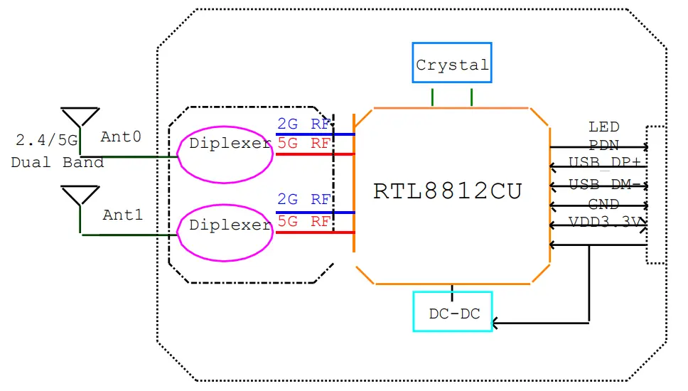
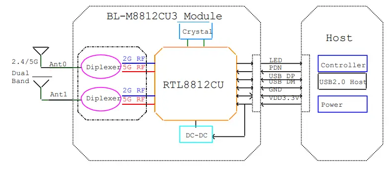
8812CU3 is a highly integrated 2*2 dual-band wireless LAN module. It combines a WLAN MAC, a 2T2R capable WLAN base banda dual-band WLAN radio. It supports IEEE 802.11a/b/g/n/ac standard and provides the highest PHY rate up to 867Mbps, It can offer feature-rich wireless connectivity and reliable throughput from an extended distance.
Features
- Operating Frequencies: 2.4~2.4835GHz and 5.15~5.85GHz
- Host Interface is USB2.0 IEEE Standards: IEEE 802.11a/b/g/n/ac
- The wireless data rate can reach up to 867Mbps
- Connect to the external antenna through
- IPEX connectors Power Supply: VDD 3.3V±0.2V
Block Diagram
General Specifications
| Module Name | 8812CU3 |
| Chipset | RTL8812CU-CG |
| WiFi Standards | IEEE802.11a/b/g/n/ac, 2T2R MIMO, 2.4G/5GHz, 867Mbps (Max) |
| Host Interface | USB2.0 |
| Antenna | Connect to the external antennas through IPEX connectors |
| Dimension | SMD 12Pins, 27.0*17.8*3.1mm (L*W*HTolerance:±0.15mm) |
| Power Supply | VDD 3.3V±0.2V @850mA Max |
| Operation Temperature | -20 to +70 |
| Operation Humidity | 10% to 95% RH (Non-Condensing) |
Pin Assignments
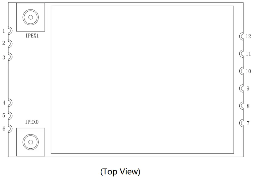
Pin Definition
| No | Pin Name | Type | Description | Supply |
| 1 | GND | RF | RF Ground | |
| 2 | NC | RF | NC (Reserved for 2.4/SG-ANT1) | |
| 3 | GND | RF | RF Ground | |
| 4 | GND | RF | RF Ground | |
| 5 | NC | RF | NC (Reserved for 2.4/5G-ANTO) | |
| 6 | GND | RF | RF Ground | |
| 7 | LED | 0 | WiFi LED Pin (Active Low, external current limiting resistor required) | VDD |
| 8 | GND | P | Ground | |
| 9 | DP+ | I/O | USB 2.0 differential pair | VDD |
| 10 | DM- | I/O | USB 2.0 differential pair | VDD |
| 11 | VDD | P | DC 3.3V power supply | |
| 12 | I | Power Down, this Pin can externally shutdown the Module (Active Low, internal pull high by 47K resistor) | VDD | |
| IPEX0 | PEX1 2.4/5G-ANT0 | RF | 2.4G / 5G RF to IPEX connector for ANT0 | |
| IPEX1 | PEX1 2.4/5G-ANT1 | RF | 2.4G / 5G RF to IPEX connector for ANT1 |
P: Power, I: Input, O: Output, I/O: In/Output, RF: Analog RF Port
Electrical and Thermal Specifications
Recommended Operating Conditions
| Parameters | Min | Typ | Max | Units | |
| Ambient Operating Temperature | -20 | 25 | 70 | °C | |
| External Antenna VSWR (Voltage Standing Wave Ratio) | 2. | 2 | |||
| Supply Voltage | 1 VDD | 3. | 3. | 4. | V |
Digital I/O DC Specifications
| Symbol | Parameter | Min | Typ | Max | Units |
| VIA | Input High Voltage | 2.0 | 3. | 4. | V |
| VIL | Input Low Voltage | — | 0 | 0.9 | V |
| VEOH | Output High Voltage | 3. | — | 3. | V |
| VOL | Output Low Voltage | 0 | — | 0.33 | V |
Current Consumption
| Conditions : VDD=3.3V ; Ta:25℃ | |||
| Use Case | VDD Current (average) | ||
| Typ | Max | Units | |
| WiFi Radio Off (Linux Driver) | 20 | 50 | mA |
| WiFi Unassociated (Linux Driver) | 100 | 150 | mA |
| 2.4G 11Mbps TX (RF-Test,1TX) for 18dBm | 340 | 380 | mA |
| 2.4G 11Mbps RX (RF-Test,1RX) | 200 | 250 | mA |
| 2.4G 6Mbps TX (RF-Test,1TX) for 16dBm | 330 | 370 | mA |
| 2.4G 6Mbps RX (RF-Test,1RX) | 200 | 240 | mA |
| 2.4G 54Mbps TX (RF-Test,1TX) for 16dBm | 240 | 270 | mA |
| 2.4G 54Mbps RX (RF-Test,1RX) | 200 | 230 | mA |
| 2.4G MCS15(HT20) TX (RF-Test,2TX) for 16dBm | 270 | 310 | mA |
| 2.4G MCS15(HT20) RX (RF-Test,2RX) | 210 | 230 | mA |
| 2.4G MCS15(HT40) TX (RF-Test,2TX) for 16dBm | 255 | 285 | mA |
| 2.4G MCS15(HT40) RX (RF-Test,2RX) | 220 | 260 | mA |
| 5.8G 6Mbps TX (RF-Test,1TX) for 16dBm | 390 | 430 | mA |
| 5.8G 6Mbps RX (RF-Test,1RX) | 190 | 210 | mA |
| 5.8G 54Mbps TX (RF-Test,1TX) for 16dBm | 255 | 285 | mA |
| 5.8G 54Mbps RX (RF-Test,1RX) | 210 | 260 | mA |
| 5.8G MCS0(HT20) TX (RF-Test,2TX) for 16dBm | 290 | 340 | mA |
| 5.8G MCS0(HT20) RX (RF-Test,2RX) | 190 | 200 | mA |
| 5.8G MCS15(HT40) TX (RF-Test,2TX) for 16dBm | 260 | 290 | mA |
| 5.8G MCS15(HT40) RX (RF-Test,2RX) | 210 | 240 | mA |
| 5.8G MCS9(VHT80) TX (RF-Test,2TX) for 14dBm | 250 | 290 | mA |
| 5.8G MCS9(VHT80) RX (RF-Test,2RX) | 210 | 230 | mA |
WiFi RF Specifications
2.4G WiFi RF Specification
| Conditions : VDD=3.3V ; Ta:25℃ | |
| Features | Description |
| WLAN Standard | IEEE 802.11b/g/n CSMA/CA |
| Frequency Range | 2.4~2.4835GHz (2.4GHz ISM Band) | ||
| Channels | Ch1~Ch11 (For 20MHz Channels) | ||
| Modulation | 802.11b (DSSS): DBPSK, DQPSK, CCK; 802.11g (OFDM): BPSK, QPSK, 16QAM, 64QAM; 802.11n (OFDM): BPSK, QPSK, 16QAM, 64QAM; | ||
|
Date Rate | 802.11b: 1, 2, 5.5, 11Mbps; 802.11g: 6, 9, 12, 18, 24, 36, 48, 54Mbps; 802.11n (HT20): MCS0~MCS7(1T1R_SISO) 6.5~72.2Mbps; 802.11n (HT20): MCS8~MCS15(2T2R_MIMO) 13~144.4Mbps; 802.11n (HT40): MCS0~MCS7(1T1R_SISO) 13.5~150Mbps; 802.11n (HT40): MCS8~MCS15(2T2R_MIMO) 27~300Mbps; | ||
| Antenna type | PCB antenna | ||
| Antenna Gain | Ant0: 6.07dBi ant1: 5.15dBi | ||
| Frequency Tolerance | ≦ ±20ppm | ||
| 2.4G Transmitter Specifications (Ant0/Ant1) | |||
| TX Rate | TX Power | TX Power Tolerance | EVM |
| 802.11b@1~11Mbps | 18dBm | ±1.5dBm | ≦-10dB |
| 802.11g@6Mbps | 16dBm | ±1.5dBm | ≦-10dB |
| 802.11g@54Mbps | 16dBm | ±1.5dBm | ≦-25dB |
| 802.11n@HT20_MCS0 | 16dBm | ±1.5dBm | ≦-10dB |
| 802.11n@HT20_MCS7 | 16dBm | ±1.5dBm | ≦-28dB |
| 802.11n@HT40_MCS0 | 16dBm | ±1.5dBm | ≦-10dB |
| 802.11n@HT40_MCS7 | 16dBm | ±1.5dBm | ≦-28dB |
| 2.4G Receiver Specifications (Ant0/Ant1) | |||
| RX Rate | Min Input Level (Typ) | Max Input Level (Typ) | PER |
| 802.11b@1Mbps | -93dBm | -5dBm | < 8% |
| 802.11b@11Mbps | -87dBm | -5dBm | < 8% |
| 802.11g@6Mbps | -91dBm | -10dBm | < 10% |
| 802.11g@54Mbps | -73dBm | -10dBm | < 10% |
| 802.11n@HT20_MCS0 | -90dBm | -10dBm | < 10% |
| 802.11n@HT20_MCS7 | -71dBm | -10dBm | < 10% |
| 802.11n@HT40_MCS0 | -86dBm | -10dBm | < 10% |
| 802.11n@HT40_MCS7 | -68dBm | -10dBm | < 10% |
5G WiFi RF Specification
| Conditions: VDD=3.3V; Ta:25℃ | |
| Features | Description |
| WLAN Standard | IEEE 802.11a/n/ac CSMA/CA |
| Frequency Range | 5.15~5.25GHz; 5.25~5.35GHz; 5.47~5.725GHz; 5.725~5.85GHz (5GHz ISM Band) | ||||
| Channels | Ch36, Ch40, Ch44, Ch48; Ch52~Ch64; Ch100~Ch140; Ch149~Ch165 (For 20MHz Channels) | ||||
| Modulation | 802.11a (OFDM): BPSK, QPSK, 16QAM, 64QAM; 802.11n (OFDM): BPSK, QPSK, 16QAM, 64QAM; 802.11ac (OFDM): BPSK, QPSK, 16QAM, 64QAM, 256QAM; | ||||
|
Date Rate | 802.11a: 6, 9, 12, 18, 24, 36, 48, 54Mbps; 802.11n (HT20): MCS0~MCS7(1T1R_SISO) 6.5~72.2Mbps; 802.11n (HT20): MCS8~MCS15(2T2R_MIMO) 13~144.4Mbps; 802.11n (HT40): MCS0~MCS7(1T1R_SISO) 13.5~150Mbps; 802.11n (HT40): MCS8~MCS15(2T2R_MIMO) 27~300Mbps; 802.11ac (VHT20): MCS0~MCS8(1T1R_SISO) 6.5~86.7Mbps; 802.11ac (VHT20): MCS0~MCS8(2T2R_MIMO) 13~173.3Mbps; 802.11ac (VHT40): MCS0~MCS9(1T1R_SISO)13.5~200Mbps; 802.11ac (VHT40): MCS0~MCS9(2T2R_MIMO)27~400Mbps; 802.11ac (VHT80): MCS0~MCS9(1T1R_SISO)29.3~433.3Mbps; 802.11ac (VHT80): MCS0~MCS9(2T2R_MIMO)58.5~866.7Mbps; | ||||
| Antenna type | PCB antenna | ||||
|
Antenna Gain | Ant0 | 5150 -5250MHz | 5.02 dBi | ||
| 5250-5350MHz | 6.15 dBi | ||||
| 5470-5725MHz | 8.46 dBi | ||||
| 5725-5850MHz | 9.23 dBi | ||||
| Ant1 | 5150 -5250MHz | 6.45 dBi | |||
| 5250-5350MHz | 6.48 dBi | ||||
| 5470-5725MHz | 7.26 dBi | ||||
| 5725-5850MHz | 5.38 dBi | ||||
| Frequency Tolerance | ≦ ±20ppm | ||||
| 5G Transmitter Specifications (Ant0/Ant1) | |||||
| TX Rate | TX Power | TX Power Tolerance | EVM | ||
| 802.11a@6Mbps | 16dBm | ±2dBm | ≦-10dB | ||
| 802.11a@54Mbps | 16dBm | ±2dBm | ≦-25dB | ||
| 802.11n@HT20_MCS0 802.11ac@VHT20_MCS0 | 16dBm | ±2dBm | ≦-10dB | ||
| 802.11n@HT20_MCS7 802.11ac@VHT20_MCS7 | 16dBm | ±2dBm | ≦-28dB |
| 802.11n@HT40_MCS0 802.11ac@VHT40_MCS0 | 16dBm | ±2dBm | ≦-10dB |
| 802.11n@HT40_MCS7 802.11ac@VHT40_MCS7 | 16dBm | ±2dBm | ≦-28dB |
| 802.11ac@VHT20_MCS8 | 16dBm | ±2dBm | ≦-30dB |
| 802.11ac@VHT40_MCS8 802.11ac@VHT40_MCS9 | 16dBm | ±2dBm | ≦-32dB |
| 802.11ac@VHT80_MCS0 | 14dBm | ±2dBm | ≦-10dB |
| 802.11ac@VHT80_MCS9 | 14dBm | ±2dBm | ≦-32dB |
| 5G Receiver Specifications (Ant0/Ant1) | |||
| RX Rate | Min Input Level(Typ) | Max Input Level(Typ) | PER |
| 802.11a@6Mbps | -90dBm | -10dBm | < 10% |
| 802.11a@54Mbps | -72dBm | -10dBm | < 10% |
| 802.11n@HT20_MCS0 | -89dBm | -15dBm | < 10% |
| 802.11n@HT20_MCS7 | -70dBm | -15dBm | < 10% |
| 802.11n@HT40_MCS0 | -86dBm | -15dBm | < 10% |
| 802.11n@HT40_MCS7 | -68dBm | -15dBm | < 10% |
| 802.11ac@VHT80_MCS0 | -84dBm | -15dBm | < 10% |
| 802.11ac@VHT80_MCS9 | -58dBm | -15dBm | < 10% |
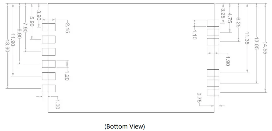
Mechanical Specifications
Module Outline Drawing
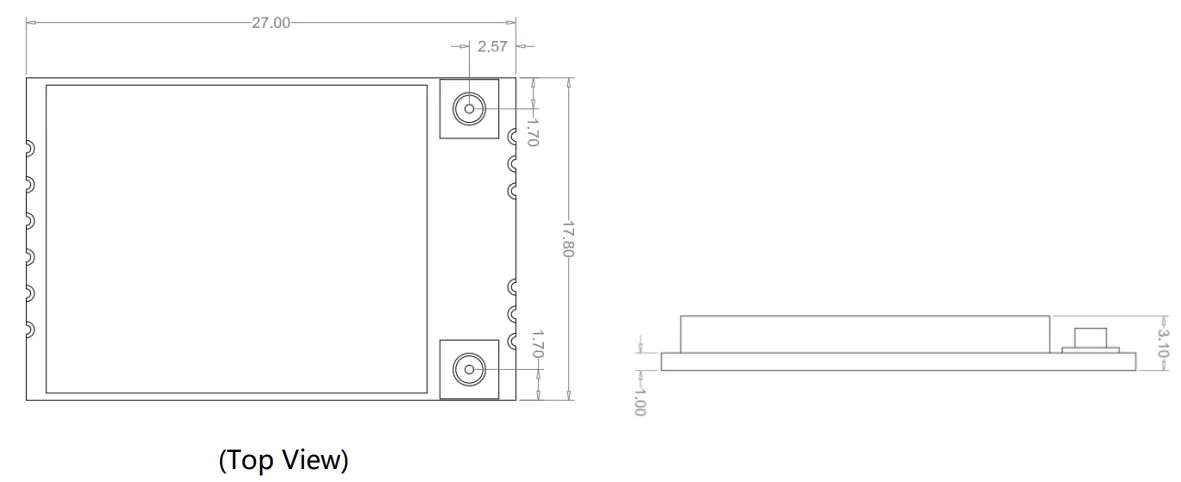
(Top View) Module dimension: 27.0mm*17.8mm*3.1mm L*W*H , Tolerance: ±0.15mm
IPEX connector dimension: 2.6*3.0*1.2mm (L*W*H, Ø2.0mm)
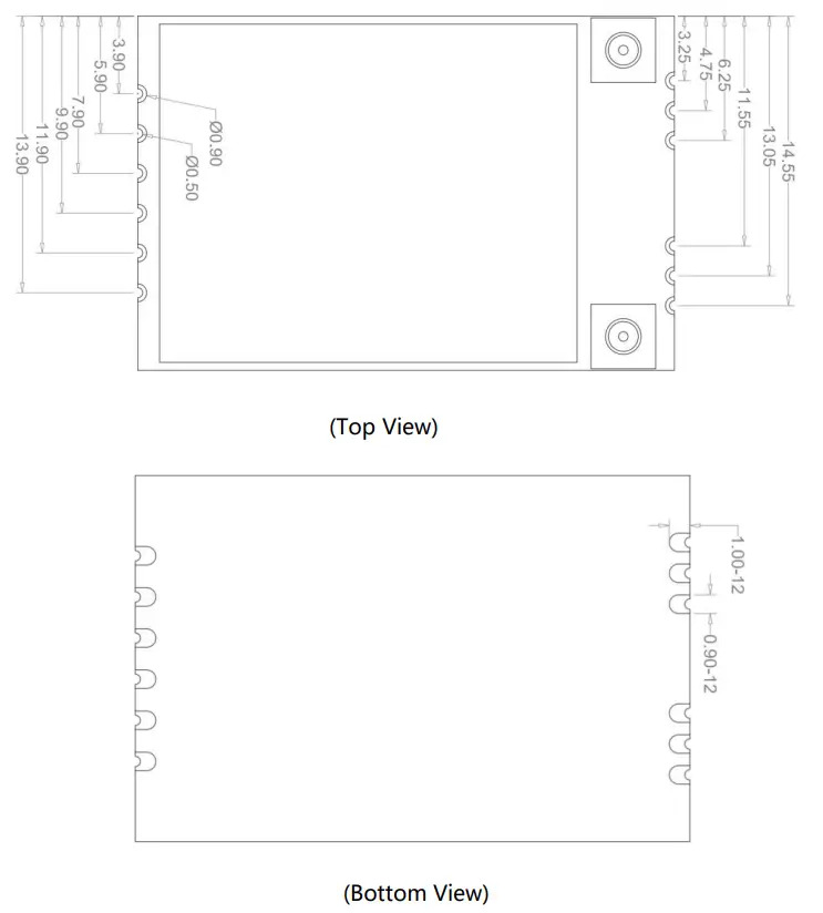
Mechanical Dimensions
 Application Information
 Application Information
Typical Application Circuit
Recommend PCB Layout Footprint
Reflow Soldering Standard Conditions
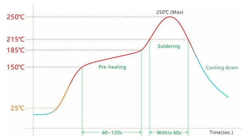
Please use the reflow within 2 times. Set up the highest temperature within 250.
Key Components Of Module
| No. | Parts | Specification | Manufacturer | Note |
| 1 | Chipset | RTL8812CU-CG | Realtek | |
| 2 | PCB | BL-M8812CU3 | Shen Zhen Tie Fa Technology limited | |
| MILLION SOURCE PRINTED CIRCUIT BOARD CO., LTD | ||||
| Quzhou Sunlord Electronics Co., Ltd | ||||
| 3 | Crystal | 40MHz-10pF-10ppm-3225 | HUBEI TKD ELECTRONICS TECHNOLOGY CO., LTD. | |
| LUCKI CM ELECTRONICS CO., LTD | ||||
| HOSONIC ELECTRONIC CO., LTD. | ||||
| 4 | Diplexer | DPX166000DT-8093A1 /DP1608-A2455BKH0T | TDK China Co., Ltd. | |
| Advanced Ceramic X |
Package and Storage Information
Package Dimensions
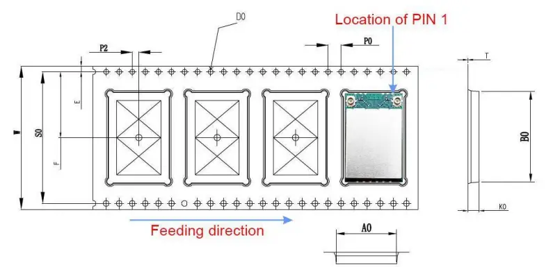
| ITEM | W | AO | BO | KO | E | F | P | PO | P2 | DO |
| DIM | 44.00+0.3 | 18.10+0.1 | 27.40+0.1 | 3.50+0.1 | 1.75±0.1 | 20.2+0.1 | 24.00+0.1 | 4.00+0.1 | 2.00+0.1 | 01.5+0.1 |
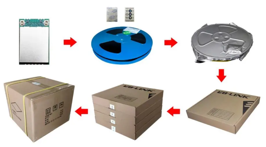
Package specification:
- 700 modules per roll and 2,800 modules per box.
- Outer box size: 5*36*29cm.
- The diameter of the blue environment-friendly rubber plate is 13 inches, with a total thickness of 48mm (with a width of 44mm carrying belt).
- Put 1 package of dry agent (20g) and a humidity card in each anti-static vacuum bag.
- Each carton is packed with 4 boxes.
Storage Conditions
Absolute Maximum Ratings:
Storage temperature: -45℃ to +85℃
Storage humidity: 10% to 95% RH(Non-Condensing)
Recommended Storage Conditions:
Storage temperature: 5℃ to +40℃
Storage humidity: 20% to 90% RH
Please use this Module within 12month after being vacuum-packaged. The Module shall be stored without opening the packing.
After the packing opened, the Module shall be used within 72hours. When the color of the humidity indicator in the packing changed, the Module shall be baked before soldering.
Baking condition: 60℃, 24hours, 1time.
ESD Sensitivity:
The Module is a static-sensitive electronic device.
Do not operate or store near strong electrostatic fields. Take proper ESD precautions!
U.S. FCC Part 15 Regulatory Information
This device complies with part 15 of the FCC Rules. Operation is subject to the following two conditions: (1) This device may not cause harmful interference, and (2) this device must accept any interference received, including interference that may cause undesired operation.
Any changes or modifications not expressly approved by the party responsible for compliance could void the user’s authority to operate the equipment.
Note: This equipment has been tested and found to comply with the limits for a Class B digital device, pursuant to part 15 of the FCC Rules. These limits are designed to provide reasonable protection against harmful interference in a residential installation. This equipment generates, uses, and can radiate radio frequency energy and, if not installed and used in accordance with the instructions, may cause harmful interference to radio communications. However, there is no guarantee that interference will not occur in a particular installation. If this equipment does cause harmful interference to radio or television reception, which can be determined by turning the equipment off and on, the user is encouraged to try to correct the interference by one or more of the following measures:
–Reorient or relocate the receiving antenna.
–Increase the separation between the equipment and receiver.
–Connect the equipment into an outlet on a circuit different from that to which the receiver is connected.
–Consult the dealer or an experienced radio/TV technician for help.
This modular complies with FCC RF radiation exposure limits set for an uncontrolled environment. This transmitter must not be co-located or operating in conjunction with any other antenna or transmitter. This modular must be installed and operated with a minimum distance of 20 cm between the radiator and the user’s body.
The device is going to be operated in the 5150~5350MHz frequency range. It is restricted to the indoor environment only.
The end product must carry a label stating “Contains FCC ID: SVN-R8812AF” or shall use e-labeling.
Manufacturer’s name and address: SHENZHEN BILAN ELECTRONIC CO., LTD 10~11/F, Building 1A, Huaqiang idea park, Guangming district, Shenzhen. Guangdong, China


