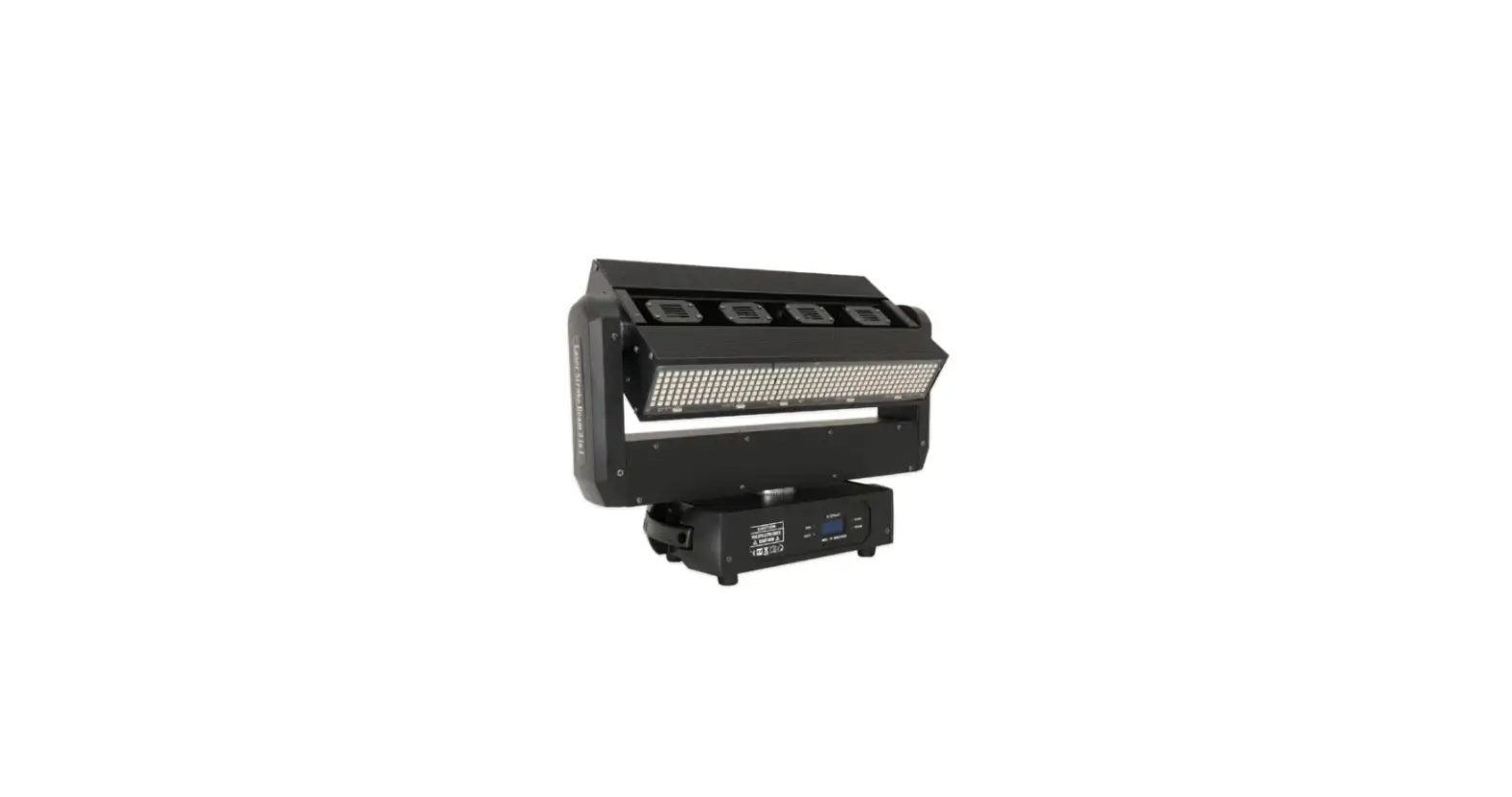
sistemamt LASERMOV12 200W RGB 3in1 Laser Moving Head
![]()
Product Information
Product Name: LASERMOV12
Power: 200W RGB 3in1 Laser Moving Head
User Manual: Included
Safety Guidance
- Avoid operating the light in a dirty and dusty environment, and clean and maintain the light regularly.
- Do not touch the wire when the light is running to preventelectric shock.
- Avoid entanglement of the power cord with other wires.
- Do not open the light housing without authorization.
- Please cut off the power when the light is not used for a long time or for maintenance.
- Do not look directly at the light when it is running.
Packing List
- Stage light: 1 piece
- Cable: 1 piece
- Manual: 1 piece
Installation Notes
- When installing this equipment, ensure that there are no flammable surfaces within at least 2.5 meters and maintain a minimum distance of 0.5 meters from the equipment to the walls.
- Before installation, confirm the power supply voltage.
Technical Parameter
- Power supply: AC 110~220V 50/60Hz
- Rated Power: 280W
- Working mode: Auto/DMX512/master-slave/ILDA/SD card
- DMX Control Channel: 6CH/40CH
- Cool system: Forced air cooling system
- Working environment: Indoor
- Working temperature: 0 – 35°C
- N.W./G.W.: 20kg/25kg
- Package size: 52*41*68cm
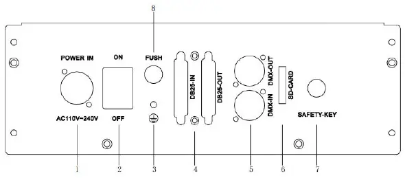
Light Control Panel
| NO. | Interface Name |
|---|---|
| 1 | Power input interface |
| 2 | Power switch |
| 3 | Ground |
| 4 | Fuse ILDA interface |
| 5 | DMX512 interface |
| 6 | SD card |
| 7 | Safety key |
| 8 | Fuse |
Light Setting
Using the touch button and LCD menu display function, the menu operation is simple and easy to use. The system software isautomatically loaded when the system is turned on, and the main menu interface is displayed.
Use the UP and DOWN buttons to select the required function menu icon. Press the OK and BACK buttons to confirm the selected function or return to the previous menu. The power indicator is always on; the working indicator flashes; when the DMX signal is connected, the DMX light flashes; when the ILDA signal is connected, the ILDA light flashes.
TFT LCD Display Control Panel Function Menu Setting
- Menu: DMX-512
- Secondary Menu: DMX-512 Channel value view CH1–CH40
- Operation Mode: Auto mode
- Show1-3 show effect Sound ON/OFF Display mode (single/order)
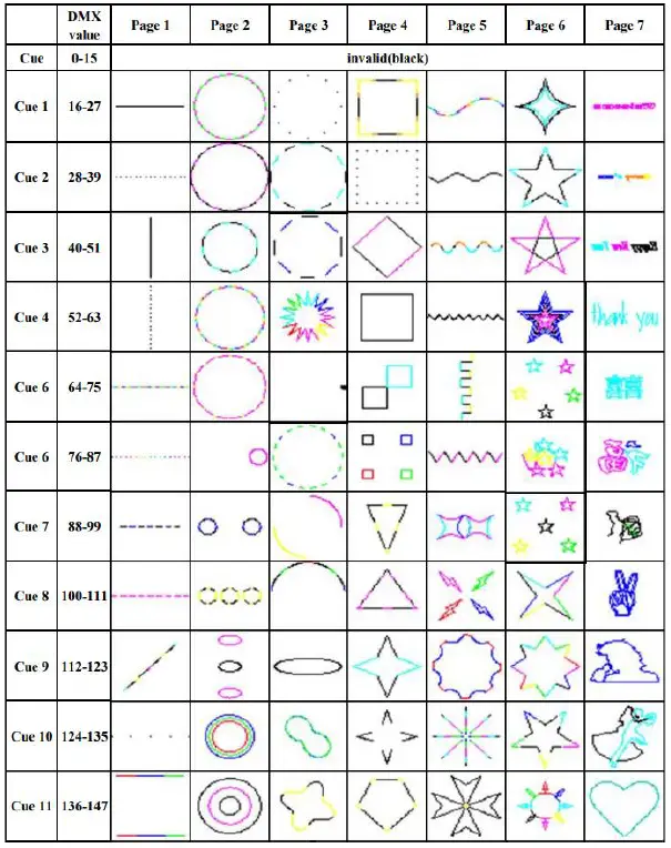
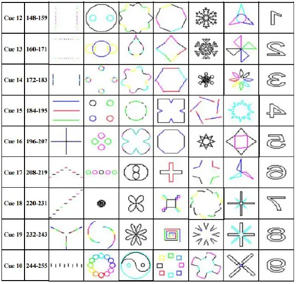
- Page 1-8 SD card mode
- Cue 1-48
- Motor speed 0-255
- X-axis starting point 0-255
- X-axis ending point 0-255
- Y-axis starting point 0-255
- Y-axis ending point 0-255
- X-axis duration time 0-255
- Y-axis duration time 0-255
- Universe
- Artnet
- Start ADDR
- RDM(ON/OFF)
- Value setting User mode (CH1-CH40 The value of each channel of the light can be customized)
- DMX Address: DMX-512 000-512
- Language: English, Chinese
- Advanced settings: Internet setup, Motor setup
- Auto IP Address: 1.192.168.1.100
- Mask 1: 255
- Mask 2: [missing value]
Safety Guidance
Thank you for choosing our products. For your safety, please read this manual carefully before operation. This manual includes installation and use information.
The equipment is packaged in good condition when leaving the factory. Please operate according to the user manual. The machine failure caused by man-made reasons is not covered by the warranty.
- When using the product, please open the light and check it carefully to ensure that there is no damage caused by transportation..
- Don’t let children operate the machine.
- Use safe ropes when fixing the equipment, and hold up the bottom when moving the light.
- The equipment must be installed in a well-ventilated place .
- Ensure that the ventilation holes are unobstructed to avoid overheating when the light is running.
- Before operation, make sure that the power supply voltage matches the power supply voltage required by the equipment.
- Please ground the conductor to prevent electric shock.
- In case of fire, do not place combustible items next to light when they are running.
- Please carefully check whether the power cord is damaged before turning on the light. If it is damaged, replace it immediately.
- To avoid electric shock or fire, avoid flammable liquid, water, metal and other electrical conductors entering the light. If any foreign body enters the light, please cut off the power supply immediately .
- Avoid operating the light in a dirty and dusty environment, and clean and maintain the light regularly.
- Do not touch the wire when the light is running to prevent electric shock. 13. Avoid entanglement of the power cord with other wires.
- Do not open the light housing without authorization
- Please cut off the power when the light is not used for a long time or for maintenance.
- Do not look directly at the light when it is running.
Packing List
This series of products are packed in standard carton, air carton is optional, please read this manual carefully before using. Follow operating rules to avoid damage to light or bodily injury. Please handle the products carefully after receiving them, and check whether the products are damaged during transportation. Open the cover of the box, take out the relevant accessories in the box, take out the light, and place the lamp on a horizontal table to facilitate related operations. Note: Do not squeeze plastic parts to avoid breakage or distortion. Check the parts as follows:
Stage light 1 pcs cable 1 pcs manual 1 pcs
Installation Notes
- When install this equipment please make sure there’s no flammable surfaces (decorated things, etc) within at least 2.5M and maintain minimum distance of 0.5M from the equipment to the walls.
- Before installation, please confirm whether the power supply voltage you are using matches the voltage marked by the light.
- Make sure that the ventilation fan and exhaust passage are not blocked by other equipment or decorative materials, such as newspapers, tablecloths, curtains, etc.
- The equipment should be fixedly installed. To ensure the stability of its installation point, at least a load-bearing structure that can withstand more than ten times the weight of the product.
- For safety reasons, this machine should be connected to a main socket with a ground wire.
Technical Parameter
- Power supply:AC 110~220V 50/60Hz
- Rated Power:280W
- Working mode:Auto/DMX512/ master-slave/ILDA/SD card
- DMX Control Channel:6CH/40CH
- Cool system: forced air cooling system
- Working environment: indoor
- Working temperature: 0℃ – 35℃
- N.W./G.W.: 20kg/25KG
- Package size:52*41*68cm
Light Control Panel
| NO. | Interface Name |
| 1 | Power input interface |
| 2 | Power switch |
| 3 | Ground |
| 4 | Fuse ILDA interface |
| 5 | DMX512 interface |
| 6 | SD card |
| 7 | Safety key |
| 8 | Fuse |
Light Setting
Using the touch button and LCD menu display function, the menu operation is simple and easy to use, and the system software is automatically loaded when the system is turned on, and the main menu interface is displayed.
Use the UP and DOWN buttons to select the required function menu icon. Press the OK and BACK buttons to confirm the selected function or return to the previous menu. The power indicator is always on; the working indicator flashes; when the DMX signal is connected, the DMX light flashes; when the ILDA signal is connected, the ILDA light flashes.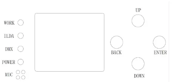
TFT LCD display control panel function menu setting ,as following:
| Menu | Secondary Menu | Third Level Menu |
|
Operation Mode | DMX-512 | DMX-512 Channel value view CH1—CH40 |
| Auto mode | Show(1-3 show effect) Sound ON/OFF | |
|
SD card mode | Display mode (single/order Page 1-8 Cue 1-48 Motor speed 0-255 |
| X-axis starting point 0-255 X-axis ending point 0-255 Y-axis starting point 0-255 Y-axis ending point 0-255 X- axis duration time0-255 Y- axis duration time0-255 | ||
| Artnet | Universe Start ADDR RDM(ON/OFF) | |
|
User mode | Value setting (CH1-CH40 The value of each channel of the light can be customized ) | |
| DMX Address | DMX-512 000-512 | |
| Language | English | |
| Chinese | ||
|
Advanced settings |
Internet setup | Auto IP |
| Address 1 192 | ||
| Address 2 168 | ||
| Address 3 1 | ||
| Address 4 100 | ||
| Mask 1 255 | ||
| Mask 2 255 | ||
| Mask 3 255 | ||
| Mask 4 0 | ||
| Motor setup | X axis horizontal reverse ON/OFF |
| Y axis horizontal reverse ON/OFF | ||
| X axis running angle 540/360 | ||
|
Scan setup | Overall size (0—255) | |
| X axis Zoom(0–255) | ||
| Y axis Zoom(0–255) | ||
| X axis invert(ON/OFF) | ||
| Y axis invert(ON/OFF) | ||
| Replace XY(ON/OF) | ||
|
Color setup | Color setup(RGB/G) | |
| Dimmer(1-100) | ||
| red(1-100) | ||
| green(1-100) | ||
| blue(1-100) | ||
|
System Config | Channel (6ch/40ch) | |
| Master/slave ×/√ | ||
| Scanner Kpss(20K~40K) | ||
| Sound Sense 0-100 | ||
| Scan safety ×/√ | ||
| Easy ILDA(OFF/ON) | ||
| LOGO(OFF/ON) | ||
| screen protect(OFF/ON) | ||
| screen invert(OFF/ON) | ||
| Motor reset ON/OFF | ||
| Reset factory setting(OFF/ON) | ||
| Factory setting | For internal factory debugging |
|
Test mode | X axis horizontal motor | 0-255 |
| Y axis horizontal motor | 0-255 | |
| Start output | Light source start output (on/off) | |
| Overall brightness (0-255) | ||
| Testing pattern | test pattern(1-4) | |
|
LED color | Black White Red Green Blue | |
|
Device Info | Channel Current device channel value | |
| Current device address | ||
| Current device running mode | ||
| EFFEC XXX effect version | ||
| Temp XXX house current device temp | ||
| HdV XXX hardware version | ||
| SV AXXX software version |
| CV BXXX control panel | ||
| MV CXXX motor version |
Use the keys to control the cursor, select the corresponding function icon, and press the “OK” button to enter the corresponding function menu setting. The menu has operating mode, address setting, language setting, advanced setting, system test, system information module. Press “BACK” to return to the main menu;
- Operation mode——only one mode can be run at the same time (ILDA signal has the highest priority)
Console mode: Select the console mode to display the number of channels currently in use for DMX control according to the desired effect. After the setting is completed, if you need to see the value of each channel, you can press the ok key to enter the channel view. The console mode is the slave mode at the same time, if it is connected to the DMX512 console signal, it is the console mode, if it is connected to the master signal, it is the slave mode.
Auto mode:Press the “●-ENTER” button to select 3 built-in effect modes. The automatic mode can be used as the master when the master-slave mode is turned on, and the slave is set to DMX mode.
SD card mode:
In SD card mode, select play mode, file, directory, motor speed, XY start and end points and stay time.
SD card play settings, the local system can read 8 fixed folders of SD card, each folder can read 48 pattern files, pattern file format (.ild) . The pattern file can be selected by the ▲UP and ▼DOWN buttons. If the loop play is set to ON, the entire SD folder will be played in a loop. (It is invalid to select a single file name.) If you want to select a single file name to play, you need to return to the loop play setup OFF . Use the ▲UP and ▼DOWN buttons to select the way to the pattern file play, ON is the music, OFF is the automatic.
Insert the SD card into the lamp and use the UP and DOWN buttons to select the SD card mode, or use the console to operate according to the channel, you can play the SD card files. In the SD card mode, you can find you by selecting the folders and files through the UP and DOWN buttons The file you need, or use the console to find the file you need, when you select the SD card mode on the lamp (ONE is a single file loop playback, FILE is a single folder all files loop playback, ALL is the entire SD card file loop playback ) Three modes
SD card file preparation :
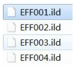
- Create a new folder in the root directory of the SD card. Only 8 folders as shown in the figure are supported. The naming rules are as shown in the figure below:

- Put standard (.IDL) files in the folder you want to put, (Note: The file name can be self-named, it is recommended to name it with numbers or letters, and the file name should not exceed 32 letters as much as possible) as follows:

- Folder playback sequence & folder content playback sequence operations are as follows:
When the files in a single folder are played, the playback order will be played in the order in which the files are copied to the SD, that is, the principle of copying first, if you need to change the playback order, you can only copy them again in the order you need. The entire SD card file is played, and the playback will be played according to a fixed folder number (the file is played in a loop from LF001 to LF008) and the sequence is also in the order of copying
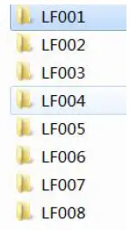
| SD card folder corresponds to the Chinese and English name | ||
| file | name(EN) | 中文名(CH) |
| LF001 | Animals | 动物 |
| LF002 | Abstracts1 | 简单几何 |
| LF003 | Abstracts2 | 抽象几何 |
| LF004 | Music+Dancers | 音乐&跳舞 |
| LF005 | People+Characters | 人物&特性 |
| LF006 | Themes | 主题 |
| LF007 | Logos+Text | Logo&文本 |
| LF008 | Shows | 表演 |
Art-NET:Optional
User mode: You can control the numerical light of each channel of the light through the operation interface.
- Address setup—— Select 0-512 address, press “●-ENTER” button to save the address code, and return to the main menu.
- language setup—— Select Chinese or English interface, press “●-ENTER” button to save the address code, and return to the main menu.
Advanced setup
- Internet setup:In Art-NET mode, set the IP address and submask
- Motor setting: X motor horizontal reverse setting, set the motor running direction is forward (clockwise direction) or reverse (counterclockwise direction); Y motor horizontal reverse setting, setting the motor running direction is forward (clockwise direction) or reverse (counterclockwise direction); X axis operating Angle setting, set the maximum operating Angle when the motor is working, can be set 360° or 540°.
- Scan setup:Overall size setting, set the overall size of the pattern; X-axis size setting, set the horizontal size of the pattern; Y-axis size setting, set the pattern vertical size; X-axis reverse, set the pattern horizontal direction interchange; Y-axis reverse, set the pattern vertical direction Swap; XY-axis replacement patterns are interchanged horizontally and vertically;
- Color setup:set the pattern to full color or single green; light source brightness, set the total brightness of the lamp; red brightness, set the red brightness of the lamp; green brightness, set the green brightness of the lamp; blue brightness, set the blue brightness of the lamp.
- System setup:Channel mode 6CH/40CH selection; master-slave setting selection; galvanometer K number setting to set the scanning rate of the galvanometer; the higher the value of voice control sensitivity from 0 to 255, the stronger the sensitivity; after the galvanometer protection setting is turned on, the working angle of the galvanometer reaches Turn off the light at a point to avoid the light source output pattern as a point; Easy ILDA, the lamp only receives ILDA signal after it is turned on, and other modes cannot emit light; whether the LOGO is turned on or not to display the LOGO interface; the screen saver can be set to be off, on or off When the screen is powered on, it is always on. When it is turned on, the screen is closed without any key operation for a long time; the screen is reversed, and the screen can be turned upside down 180 degrees; the motor is reset, and the motor position is manually reset; the factory settings are restored, and the parameters Set to the initial setting when leaving the factory (the channel mode value and DMX512 address remain unchanged)
Testing mode—Equipment self-check
The test mode is a special mode. It can only be called after entering the test mode interface. After exiting the interface, the previous operation mode will be restored. In the test mode, turn on the light source and select the test chart to check whether there is a problem with the lamp.
Device Info— Display related information of the system Channel value DMX channel of current fixture setting Address code of the working address of the current fixture Operating mode The current working mode of the fixture Effect version Built-in effect version of the system Chassis temperature Internal temperature of lamps Hardware version number Batch of lamp program board Software version number Lamp program version Control panel Control panel program version number (you can judge whether the control board information is read)
Motor mode motor mode program version number (you can judge whether the control board information is read)
The scanner detection error reporting function: power ON the machine and start the scanner self-check. If either of the two axes displays ON, it indicates that the scanner has a problem. Selecting any mode will not work.
Light Control mode
ILDA control mode
Use DB25 ILDA signal line to connect the device, the device will receive ILDA signal first, ILDA signal has the highest priority: ILDA>DMX512 DMX512 control mode
Set the DMX512 address code, the lamp will receive the standard
DMX512 signal
Master —In the main menu, press the ▲UP、▼DOWN buttons to enter and select the “System Settings” menu / the host is set to ON (default is OFF), and the lamp is the host at this time.
Slave—In the main menu, press the UP and DOWN buttons to enter and select the “System Settings” menu / the slave is set to OFF (default is OFF), press the BACK button to return to select the “DMX Address” menu. DMX address is set to 001 and the lamp is the slave.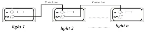
Auto mode
When the lamp is not connected to an external signal, the device can choose to run automatically.
User mode:
The numerical value lamps of each channel of the lamps can be controlled through the operation interface
DMX512 Control
DMX512 Connect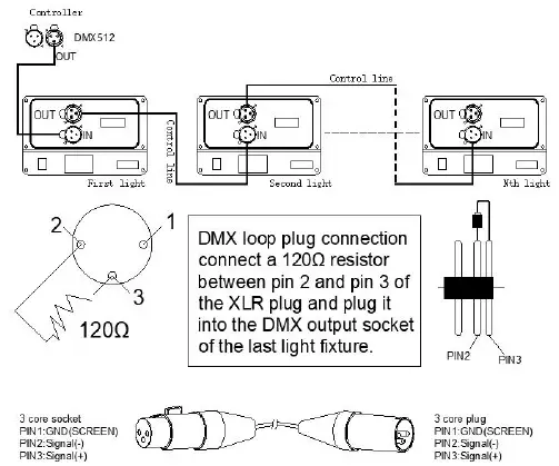
- In order to reduce signal errors and avoid signal weakening or interference during transmission, a 120Ω resistance loop can be inserted between the 2 cores and the 3 cores of the DMX output terminal of the last machine.
- Connect the lamp with XLR signal, one end is connected to the output port of the lamp, and the other end is connected to the input port of the next lamp.
XLR signal lines can only be used in series, not in parallel. DMX512 signal transmission speed is very fast. Damage to the signal line, weak welding, poor contact, etc., will affect the signal transmission and cause the system to shut down. - When a unit of machine power disconnect, DMX output or input connection is bypass, in order to maintain the DMX line and connectivity.
- Each lamp must have an address code, which can receive the information sent by the console, ranging from 1 to 512.
- The terminal of the DMX512 system needs to be equipped with a terminator to reduce signal transmission errors.
- The 3-pin XLR connector is more common than the 5-pin XLR: 3 pin XLR:PIN1:GND,PIN2:- Signal ,PNI3:+ Signal 5 pin XLR:PIN1:GND,PIN2:- Signal,PIN3:+ Signal,PIN4/PIN5:No USE
Chanel setting:
Press the MENU button to enter the menu mode, select the system setting/channel mode (6/40CH), select the channel mode you need, and press the ENTER key to confirm.
Connect the XLR control line from the DMX output of the controller to the DMX input of each luminance, and so on until all the luminance are connected, and then connect the loop plug to the signal output of the last luminance to complete the connection ,As following :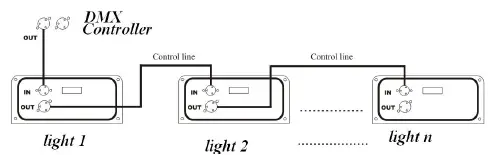
When using any controller, each controller must have its own address. Therefore, the address of the first light fixture is set to 1, the address code of the second light fixture is set to 7 or 34 (address code 1 of the first light fixture plus 6 or 33 channels), and the third light fixture is set to 13 or 67. And so on (this setting will depend on the different console to decide, now just as a general rule).
Specific dmX-512 signal control mode address code switch Settings are as follows:
| Light NO. | Start Address | Display(ON) |
| 1 | 1 | 1 |
| 2 | 7 or 41 | 007or 041 |
| 3 | 13 or 81 | 013 or 081 |
| ┇ | ┇ | ┇ |
DMX-512 Channel introduce:
6CH When u use 6 CH, only Motor Chanel CH1-CH6 valid.
40CH Chanel data
| Chanel | Chanel value | Content |
| CH1 | 0~255 | X axis motor (X motor position) |
| CH2 | 0~255 | X motor Fine-tuning |
| CH3 | 0~255 | Y axis motor (X motor position) |
| CH4 | 0~255 | Y motor Fine-tuning |
| CH5 | 0~255 | XY motor speed choose |
| CH6 | 0~255 | XY motor reset (When the value is 255, after 20S ,reset) |
|
CH7 | 0~31 | Blackout(off) |
| 32~63 | Manual play | |
| 64~127 | Auto play macro function | |
| 128~255 | SD PLAY mode, please refer to the SD card channel | |
| CH8 | 0~255 | Dimmer Brightness 0% ~ 100% |
| CH9 | 0~255 | Red brightness 0% ~ 100% |
| CH10 | 0~255 | Green brightness 0% ~ 100% |
| CH11 | 0~255 | Blue brightness 0% ~ 100% |
|
CH12 |
0~255 | Each 32 value be one page,total 8 page ( CH1= 32-61 is valid) |
| Each 10 value be one macro function, total 25 cue ( CH1= 62-128 is valid) | ||
| CH13 | 0~15 | Blackout(off) |
| 16~255 | each 12 values be one cue, total 20 cues;(choose cues) | |
| CH14 | 0~255 | From left to right(128 center) |
| CH15 | 0~255 | X axis fine position |
| CH16 | 0~255 | From bottom to top(128 center) |
| CH17 | 0~255 | Y axis fine position |
| CH18 | 0~255 | Clockwise rotation (0°-360°) |
| CH19 | 0~255 | Fine rotation |
| CH20 | 0~255 | Zoom,From 100% to 0% |
| CH21 | 0~255 | From left to right (X rotation) |
| CH22 | 0~255 | From bottom to top(Y rotation) | |||||||
|
CH23 | Choose color | ||||||||
| 0~7 | Default color | 8~63 | 7 pcs different color | ||||||
| 64~127 | Each 8 value be one effect,total 8 effect | ||||||||
| 128~143 | Macro function 1 | 144~159 | Macro function 2 | ||||||
| 160~175 | Macro function 3 | 176~191 | Macro function 4 | ||||||
| 192~207 | Macro function 5 | 208~223 | Macro function 6 | ||||||
| 224~239 | Macro function 7 | 240~255 | Macro function 8 | ||||||
| CH24 | 0~255 | Visible point 100%-0%-0 | |||||||
|
CH25 | Pattern Deformation (with zoom channel (14) (25)) | ||||||||
| 0~15 | Invalid | 16~31 | Macro function 1 | 32~47 | Macro function 2 | ||||
| 48~63 | Macro function 3 | 64~79 | Macro function 4 | 80~95 | Macro function 5 | ||||
| 96~111 | Macro function 6 | 112~127 | Macro function 7 | 128~ 143 | Macro function 8 | ||||
| 144~159 | Macro function 9 | 160~175 | Macro function 10 | 176~ 191 | Macro function 11 | ||||
| 192~207 | Macro function 12 | 208~223 | Macro function 13 | 224~ 255 | Default | ||||
|
CH26 | Wave mode( when value=0 Invalid ) | ||||||||
| 1~39 | Macro function 1 | 40~79 | Macro function 2 | 80~ 119 | Macro function 3 | ||||
| 120~159 | Macro function 4 | 160~199 | Macro function 5 | 200~ 255 | Macro function 6 | ||||
| CH27 | Write in ( when value=0 Invalid ) | ||||||||
| 1~42 | Macro | 43~84 | Macro function 2 | 85~ | Macro function 3 | ||||
| function 1 | 126 | |||||
| 127~255 | Strobe mode( from slow to fast) | |||||
|
CH28 | X horizontal position ( when value=0 Invalid ) | |||||
| 0 | Invalid | 1~32 | Macro function 1 | 33~64 | Macro function 2 | |
| 65~96 | Macro function 3 | 97~128 | Macro function 4 | 129~ 160 | Macro function 5 | |
| 161~192 | Macro function 6 | 193~224 | Macro function 7 | 225~ 255 | Macro function 8 | |
|
CH29 | Y Vertical position ( when value=0 Invalid ) | |||||
| 0 | Invalid | 1~32 | Macro function 1 | 33~64 | Macro function 2 | |
| 65~96 | Macro function 3 | 97~128 | Macro function 4 | 129~ 160 | Macro function 5 | |
| 161~192 | Macro function 6 | 193~224 | Macro function 7 | 225~ 255 | Macro function 8 | |
|
CH30 | Rotation ( when value=0 Invalid ) | |||||
| 0 | Invalid | 1~32 | Macro function 1 | 33~64 | Macro function 2 | |
| 65~96 | Macro function 3 | 97~128 | Macro function 4 | 129~ 160 | Macro function 5 | |
| 161~192 | Macro function 6 | 193~224 | Macro function 7 | 225~ 255 | Macro function 8 | |
|
CH31 | Zoom ( when value=0 Invalid ) | |||||
| 0 | Invalid | 1~32 | Macro function 1 | 33~64 | Macro function 2 | |
| 65~96 | Macro function 3 | 97~128 | Macro function 4 | 129~ 160 | Macro function 5 | |
| 161~192 | Macro | 193~224 | Macro function 7 | 225~ | Macro function 8 | |
| function 6 | 255 | |||||
|
CH32 | X Rotation ( when value=0 Invalid ) | |||||
| 0 | Invalid | 1~32 | Macro function 1 | 33~64 | Macro function 2 | |
| 65~96 | Macro function 3 | 97~128 | Macro function 4 | 129~ 160 | Macro function 5 | |
| 161~192 | Macro function 6 | 193~224 | Macro function 7 | 225~ 255 | Macro function 8 | |
|
CH33 | Y Rotation ( when value=0 Invalid ) | |||||
| 0 | Invalid | 1~32 | Macro function 1 | 33~64 | Macro function 2 | |
| 65~96 | Macro function 3 | 97~128 | Macro function 4 | 129~ 160 | Macro function 5 | |
| 161~192 | Macro function 6 | 193~224 | Macro function 7 | 225~ 255 | Macro function 8 | |
| CH34 | LED Dimmer | 0~255 | 0-100% (dark-bright) | |||
| CH35 | LED strobe | 0~255 | 0-100%(slow-fast) | |||
| CH36 | LED macro function | 0~255 | each 4 values be one cue, total 64 cues | |||
| CH37 | LED speed | 0~255 | LED macro speed from slow to fast | |||
| CH38 | LED red | 0~255 | 0-100%(Red brightness) | |||
| CH39 | LED green | 0~255 | 0-100%(Green brightness) | |||
| CH40 | LED blue | 0~255 | 0-100%(Blue brightness) | |||
33CH SD card Chanel data:
| Chanel | Chanel value | content | |
| CH1 | X motor | 0~255 | X motor |
| CH2 | X motor fine position | 0~255 | X motor fine position |
| CH3 | Y motor | 0~255 | Y motor |
| CH4 | Y motor fine position | 0~255 | Y motor fine position |
| CH5 | Motor speed | 0~255 | XY motor speed |
| CH6 | Motor reset | 0~255 | (When the value is 255, after 20S ,reset) |
|
CH7 | Built in pattern mode | 0~127 | please refer to 33CH table for details |
|
SD mode | 128~159 | Manual play | |
| 160~191 | File display | ||
| 192~223 | Music trigger manual play choose pattern | ||
| 224~255 | Music trigger manual play choose pattern | ||
| CH8 | Dimmer | 0~255 | Dimmer Brightness 0% ~ 100% |
| CH9 | Red | 0~255 | Red brightness 0% ~ 100% |
| CH10 | Green | 0~255 | Green brightness 0% ~ 100% |
| CH11 | Blue | 0~255 | Blue brightness 0% ~ 100% |
| CH12 | pattern group | 0~255 | .Each 32 value be one page,total 8 page ( CH1= 32-61 is valid) |
| CH13 | pattern | 0~15 | Off |
| 16~255 | Each 5 value be one macro function, total 48 cue | ||
| ( CH1= 62-128 is valid) | |||||
| CH14 | X position | 0~255 | From left to right(128 center) | ||
| CH15 | X fine position | 0~255 | X axis fine position | ||
| CH16 | X position | 0~255 | From bottom to top(128 center) | ||
| CH17 | X fine position | 0~255 | Y axis fine position | ||
| CH18 | Rotation | 0~255 | Clockwise rotation (0°-360°) | ||
| CH19 | Fine rotation | 0~255 | Fine rotation | ||
| CH20 | Zoom | 0~255 | Zoom,From 100% to 0% | ||
| CH21 | X rotation | 0~255 | From left to right (X rotation) | ||
| CH22 | Y rotation | 0~255 | From bottom to top(Y rotation) | ||
|
CH23 |
Color | 0~7 |
Default color | 8~63 | 7 pcs different color |
| 64~127 | Each 8 value be one effect,total 8 effect | ||||
| 128~143 | Macro function 1 | 144~159 | Macro function 2 | ||
| 160~175 | Macro function 3 | 176~191 | Macro function 4 | ||
| 192~207 |
Macro function 5 | 208~223 | Macro function 6 | ||
| 224~239 | Macro function 7 | 240~255 | Macro | ||
| function 8 | |||||
| CH24 | Writer in | 0~255 | Visible point 100%-0% | ||
|
CH25 | Speed | 0~15 | 100% speed | ||
| 16~31 | pause | ||||
| 32~255 | 25%-200% | ||||
|
CH26 | Scan Kpss | 0~31 | Default | ||
| 32~223 | 6K~29K | ||||
| 224~255 | 30K | ||||
| CH27 | LED Dimmer | 0~255 | 0-100% (dark-bright) | ||
| CH28 | LED strobe | 0~255 | 0-100% (slow-fast) | ||
| CH29 | LED macro | 0~255 | 4 value be one macro function, total 64 cue | ||
| CH30 | LED speed | 0~255 | LED macro 0-100% (slow to fast) | ||
| CH31 | LED red | 0~255 | Red | ||
| CH32 | LED green | 0~255 | Green | ||
| CH33 | LED blue | 0~255 | Blue | ||
Built in effect list
Maintenance
- Maintenance should be performed every 15-day period, by using a sponge which is dipped with alcohol, rather than wet cloth or other chemical liquid, to clean the mirror.Always disconnect from the power when the device is not in use or before cleaning it.
- Cooling fan cleaning: Use compressed air to clean the fan of the device. The fan position plays a vital role in the normal operation of the device. Please ensure the normal operation of the fan.
- When the equipment is used frequently, the fan should be cleaned every 1 month, or in a dusty and oily environment, the number of cleanings should be increased. The actual operation should be implemented according to the application environment of the equipment to ensure the normal operation of the fan.
- Internal optical cleaning: cleaning internal optical components requires professional authorized technicians to operate. Incorrect cleaning techniques or improper cleaning choices can cause serious damage to the equipment. Since the optical part and the rest of the light source system are separated and sealed, this operation should not be performed more than once a year.
Warning and Declaration
Do not look directly at the light source with your eyes when turning on the light. Before any installation and maintenance work, please make sure that the power has been cut off.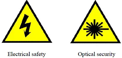
| Product common breakdown comparative chart | |
| breakdown cause | Major breakdown analysis and solution |
| The light no emitting or no work | 1. Check the power cable whether to connect the light,whether the fuse does burn out |
| 2. Check the input voltage whether to assign the voltage match with the light. Check work order is normal reset or not. | |
|
No sound control | 1. Check whether the keys on the display screen are set to the voice control mode according to the instructions. 2. If the sound sensitivity value is small, select a larger value. |
| The light can emit light normally and is not controlled by the controller | 1. Check whether the start address code of the display screen of the light is set correctly. 2. Check whether the XLR signal is damaged. |
| Master-slave synchronization mode, the master is normal, and the slave is abnormal | 1. Confirm that there is only one host, and the host is not connected to the DMX console, and set to voice control or auto-propelled mode. 2. There is still a problem with the correct master and slave settings, please check the online line. |
| Key failure, no work | 1.Check whether any of the keys has not been reset normally. |
| The light is dim and the brightness is obviously reduced | 1. Check whether the light source has reached the expiration date. 2. Check whether the internal and external optical system is clean. |
| If the fault cannot be eliminated according to the above method, please contact with dealer. | |


