TELRAN GJs03-M6AX-24-96C-I Dome Fiber Optic Splice Closure Instruction Manual

Introduction
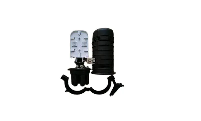
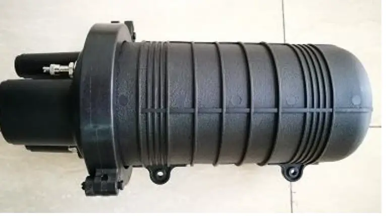
This product is used to connect the distribution cable and the incoming cable, is widely applied in communication, network systems, CATV cable TV and so on. It adopts scientifically formulated engineering plastic and be shaped by injection molding, with anti aging, anti-corrosion, flame retardant, waterproof, anti-vibration and anti-shock effects. Can effectively prevent the optic fibers from the influence of outdoor environment.
Dome-to-base design; up to 4 pieces splice trays, hinge for access of any splice without disturbing others trays; Fast and reliable sealing performance, easy to package multiple times. With lightning protection grounding device, it can be applied in overhead, wall mounting or directly buried.
Specification
| Model: | GJS03-M6AX- 96-I | ||
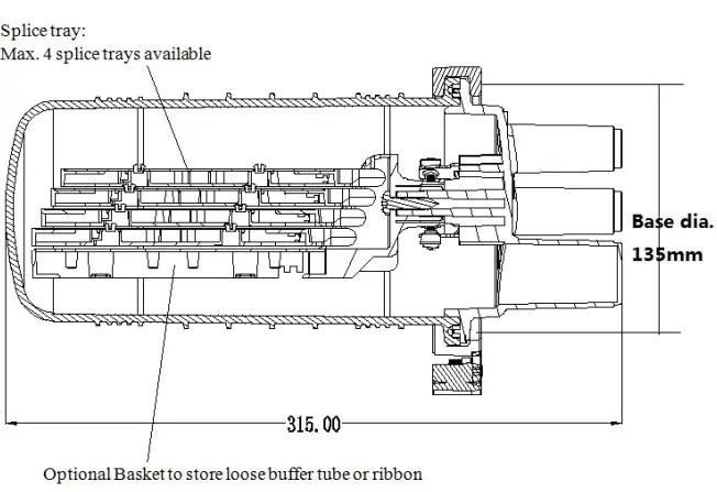
| Size: With clamp’s biggest outer dia. | 315*188.8mm | Raw material | Dome, Base: modified PP, clamp: Nylon +GF Tray: ABS Metal parts:Stainless steel |
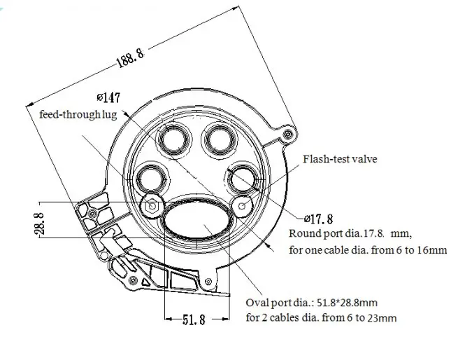
| Entry ports number: | 1 oval port, 4 round ports | Available cable dia. | Oval port:available for 2 pcs, 6~23mm cables Round ports:Each available for 1pc 6-16mm cable |
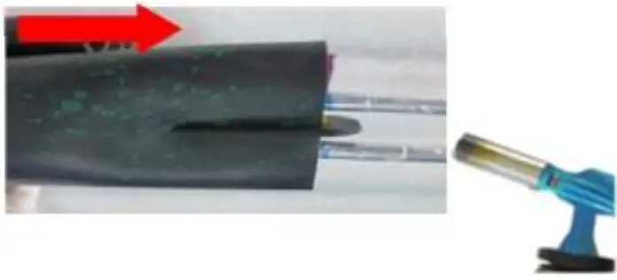
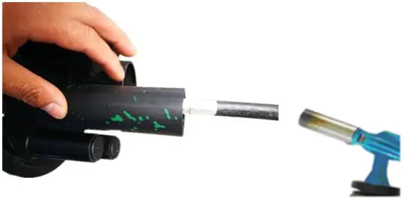
| Max. tray number | 4 trays | Base sealing method | Heat-shrink |
| Tray capacity: | 24 F | Applications: | Aerial, directly buried, Wall/pole mounting |
| Max. closure splice capacity | 96 F | IP grade | 68 |
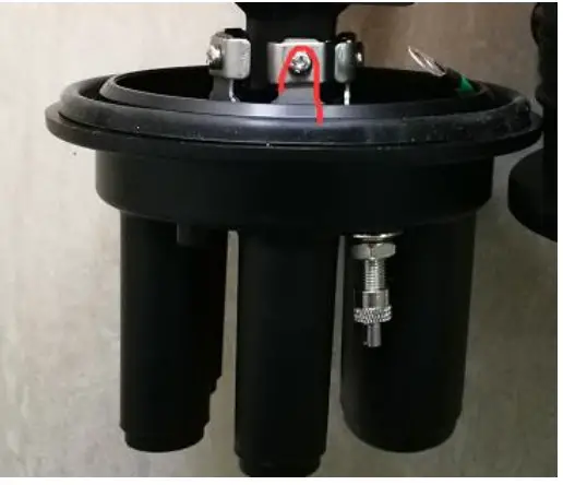
Outer Structure]
Technical Parameter
- Working Temperature: -40° centigrade ~ +65° centigrade
- Atmospheric Pressure: 62 ~ 106Kpa
- Axial Tension: >1000N/1min
- Flatten Resistance: 2000N/100 mm (1min)
- Insulation resistance: >2*104MΩ
- Voltage Strength: 15KV(DC)/1min, no arc over or breakdown
- Temperature recycle: under -40°C ~+65°C , with 60(+5)Kpa inner pressure, in 10cycles; Inner pressure shall decrease less than 5 Kpa when closure turn to normal temperature
Main components
| Name / Picture | Qty | Name / Picture | Qty |
Dome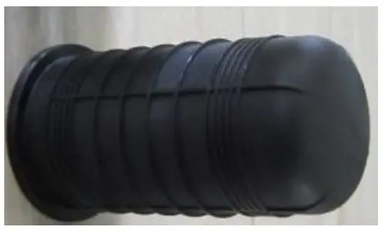 | 1pc | Tray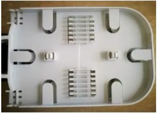 | Max. 4 pcs |
Clamp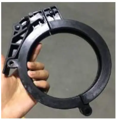 | 1pc | Value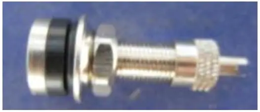 optional | 1pc |
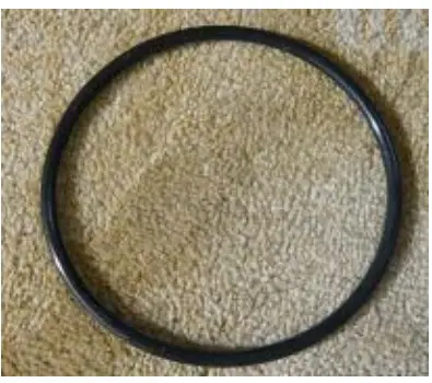
Base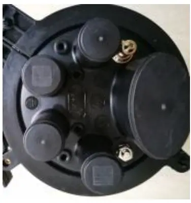 | 1pc | Modified O-ring
| 1pc |
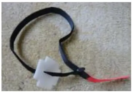
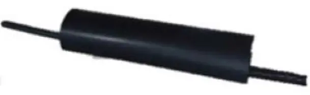
Cable Strengthen member attach plate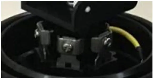 | 1set | Velcro strip with one X flake
| 1pc |
| Name / Picture | Qty | Name / Picture | Qty |
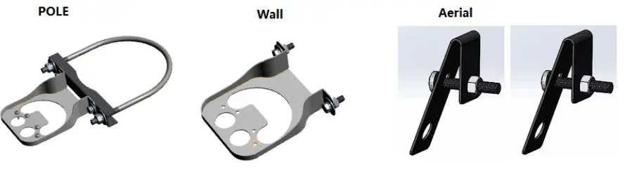
Pole mounting kits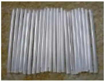 optional | 1 Standard offered with | Aerial mounting kits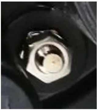 optional | Order as optional |
Wall mounting kits  optional | Order as optional | ||
| Name / Picture | Qty | Items | |
Ports sealing accessories bag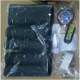 | 1 bag | Name / Picture | Qty |
Small Heat-shrink tube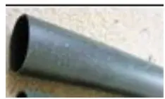 | 4 | ||
Abrasive tape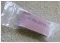 | 1 | ||
Aluminium foil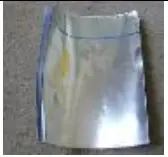 | 6 | ||
Big Heat-shrink tube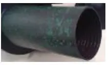 | 1 | ||
Cleaning tissue optional | 1 | ||
Desiccant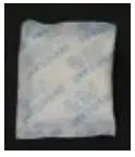 optional | 1 | ||
Shield continuity wire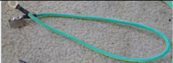 installed on the base when supply optional | 1 | ||
AMP clamp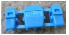 optional | 1 | ||
Branch off clip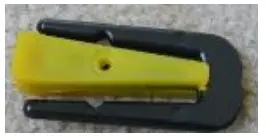 | 1 | ||
Installation Guidance
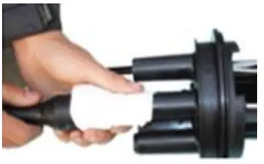
- Cut the ports need to guide-in cable.

- Put the cable through the heatshrink tube

- Remove the sheath of the cable and clean it. Cut the strengthen member to 5cm length. Put it through the attach screws and bend it to fix on the screw. Then tighten the screw.

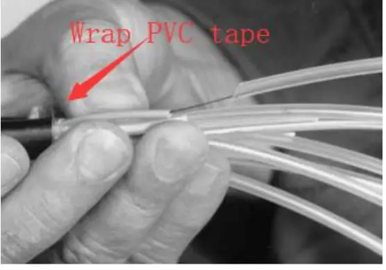
- Remove the loose tube of the cable and clean the bare fibers. Put them through the transparent PE tube strip by strip. Using PVC tape to wrap the end of the PE tube and cable.

- Wind the excessive loose buffers in suitable cycles and put in the storage basket.

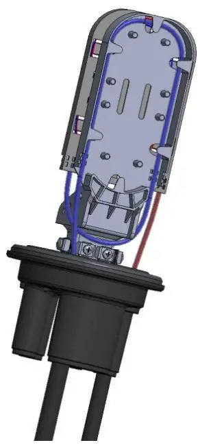
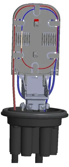
- Coiling the optic fibers in the splice trays as above picture from the bottom tray to the top one. Fusion the joints and shrink the protective tubes and fix them in the tray. And put on the tray lid.

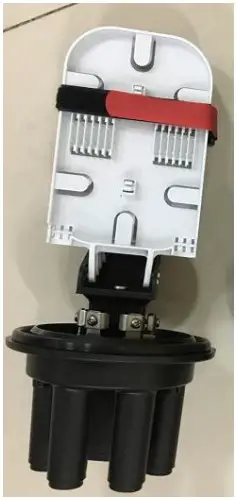
- Use the Velcro strip to bind the trays.

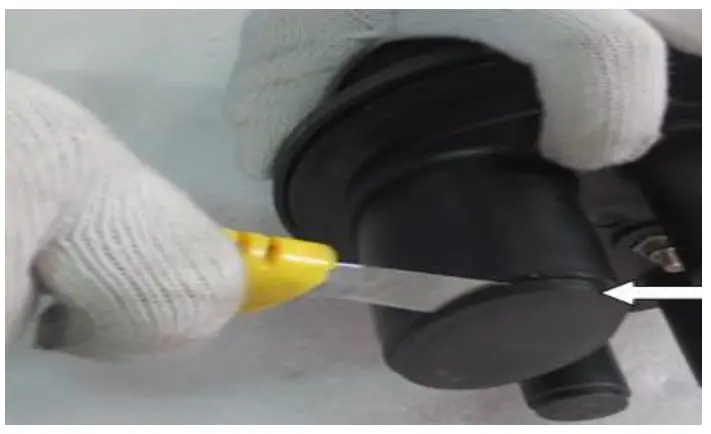
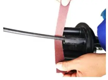
- Using abrasive strip to rough the surface of the cable sheath and ports slightly.

- Clean the cable surface and ports

- Cut the ports need to guide-in cable.

- Put the cable through the heatshrink tube

- Remove the sheath of the cable and clean it. Cut the strengthen member to 5cm length. Put it through the attach screws and bend it to fix on the screw. Then tighten the screw.

- Remove the loose tube of the cable and clean the bare fibers. Put them through the transparent PE tube strip by strip. Using PVC tape to wrap the end of the PE tube and cable.

- Wind the excessive loose buffers in suitable cycles and put in the storage basket.
- Coiling the optic fibers in the splice trays as above picture from the bottom tray to the top one. Fusion the joints and shrink the protective tubes and fix them in the tray. And put on the tray lid.
- Use the Velcro strip to bind the trays.
- Using abrasive strip to rough the surface of the cable sheath and ports slightly.
- Clean the cable surface and ports
19 Hayezira St. Industrial Zone Ramla 7255616
fax. 03-5214524
phone: 03-5575110


