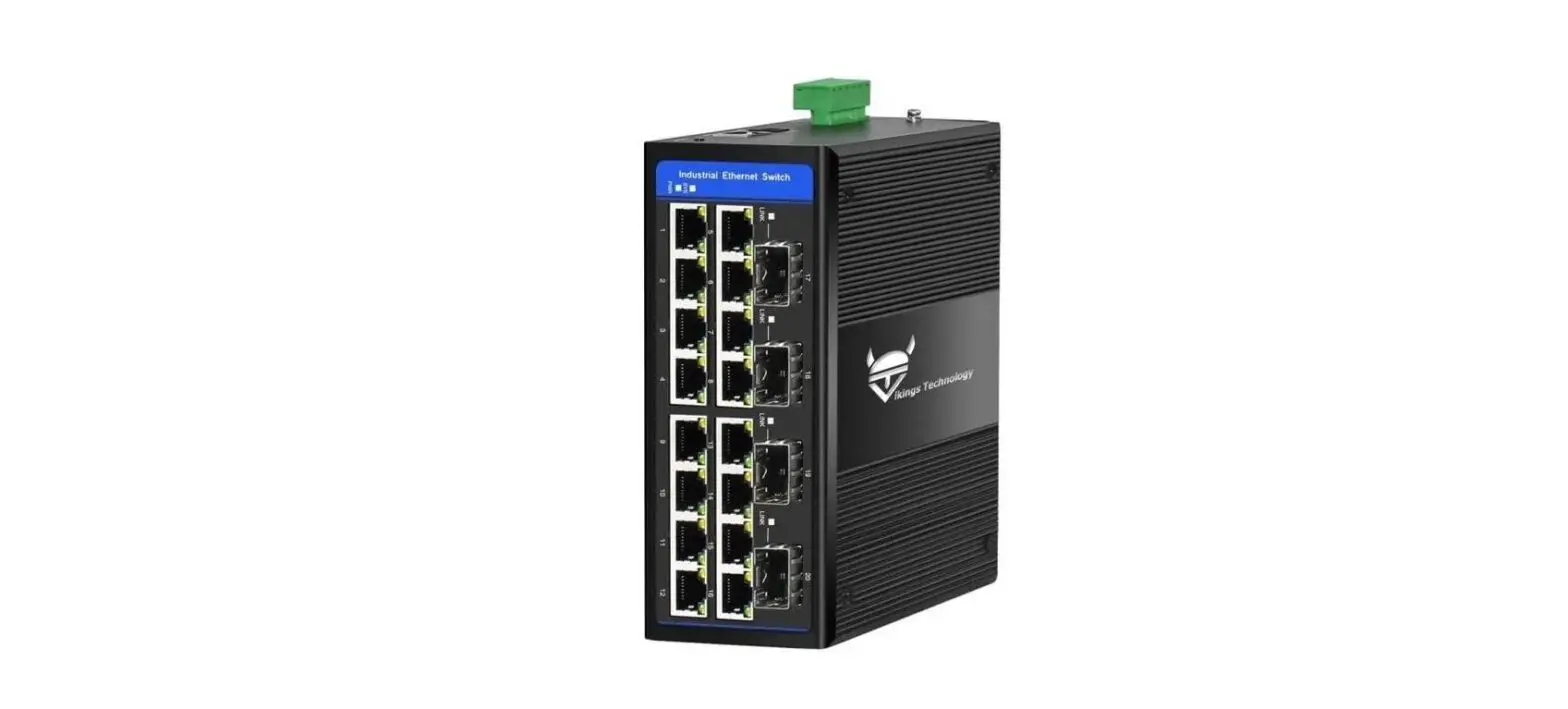
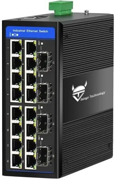
vikings SMG1640-D3 Managed Industrial Switch
Overview
The SMG1640-D3 Managed Industrial Switch supports up to 16*10/100/1000 Base-TX RJ45 + 4*100/1000Base-X SFP ports. The PoE version (SMG1640P-D3) provides PoE (IEEE802.3af/at) as Power Sourcing Equipment (PSE) up to 30W per port, up to 300W total.
Package Contents
- SMG1640-D3 (SMG1640P-D3) Switch x 1
- This Quick Installation Guide x 1
Installation
- To install the switch on a DIN rail, lock the upper part of the DIN rail clip on the upper side of the DIN rail and then gently press it until the clip is securely locked on the rail.
- To install it on the wall – re-position the wall-mount plates, which are already screwed on the unit. Remove din-rail clip if it interferes to mount the unit on the wall.
- Connect your network devices to the RJ45 switch ports with network cables.
- Insert selected SFP modules into the SFP ports. Connect fiber cables to the SFP modules fiber ports.
- Connect your power supply (range: 9-56VDC for non-PoE, 48-52VDC for PoE model) to green terminal block to V1+ and V1- pins. If power to be supplied from redundant power sources, connect second power supply to V2+ and V2- pins.
- Power up your power supply(-ies) to power up the unit.
- If all cables are correctly connected, the indicators will lit as per LEDs status:
LEDs status
| LED | Color | Indication |
| PWR | Green | Lit when unit is powered |
| SYS | Green | Lit when system is running normally |
| LINK (SFP ports) | Green | Steady Lit when fiber link is established Blink when data is being transmitted |
|
(RJ45 ports) | Yellow | Steady Lit when connection is established Blink when data is being transmitted |
| Green | Steady Lit when 1000Mbps link is established Off when 10/100Mbps link is established |
Web login
- Connect the switch to your PC with a network cable
- Set your PC’s fixed IP address to 192.168.1.2
- In your PC’s browser enter the default switch’s IP address: 192.168.1.6
- Default Username: admin
- Default Password: admin
- For settings details, please check Switch’s web user manual
Contact information
Vikings Technology Co., LTD. www.vikingstechnology.com [email protected]


