![]()
D-Link
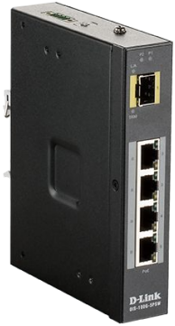
DIS-100G-5PSW
Industrial Unmanaged Switch with 4 10/100/1000Base-T PoE Ports and 1000Base-X SFP Port
Quick Installation Guide
Information in this document is subject to change without notice.
© 2018 D-Link Corporation. All rights reserved.
Package Contents
Open the shipping carton of the switch and carefully unpack its contents. The carton should contain the following items:
- DIS-100G-5PSW switch
- DC power terminal block
- Wall mounting kit
- DIN-Rail mounting kit
- Quick Installation Guide
Hardware Overview
Interfaces
| Interface | Description |
| Port 1 | 1000Base-X SFP port |
| Ports 2-5 | 1000Base-T PoE ports |
Table 1
LED Indicators
| LED | Status | Description |
| PoE (Ports 2-5) | On green | PoE is working. |
| Off | PoE is not working. | |
| P1 | On green | P1 power line has power. |
| Off | P1 power line is disconnected or does not have power supply. | |
| P2 | On green | P2 power line has power. |
| Off | P2 power line is disconnected or does not have power supply. | |
| Link/Act (Port 1) | On green | Ethernet link is up. |
| Off | Ethernet link is down. | |
| 1000 (Port 1) | On yellow | SFP port 1000 Mbps connection is detected. |
| Off | No link or SFP port 100 Mbps connection is detected. | |
| Link/Act (Ports 2-5) | On green | Ethernet link is up. |
| Blinking green | Ethernet link is up and there is traffic detected. | |
| Off | Ethernet link is down. | |
| Speed (Ports 2-5) | On yellow | 1000 Mbps connection is detected. |
| Off | No link or 10/100 Mbps connection is detected. |
Table 2
DIP-switches
| Pin № | State | Description |
| Pin 1 | ON | To enable broadcast storm rate limit. |
| OFF | To disable broadcast storm rate limit. | |
| Pin 2 | ON | Not used. |
| OFF | Not used. |
Table 3
Hardware Installation
DIN-Rail Mounting
Mounting steps:
- Screw the DIN-Rail bracket on with the bracket and screws in the accessory kit.
- Hook the unit over the DIN-Rail.
- Push the bottom of the unit towards the DIN-Rail until it snaps into place.
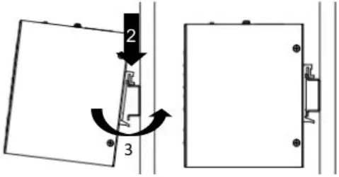 Figure 1 — Mounting the switch on a DIN-Rail
Wall Mounting
Screw on the wall-mount plate on with the plate and M4 screws in the accessory kit.
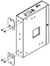 Figure 2 — Attaching brackets to the switch
 Figure 3 — The switch with the attached wall mounting brackets
Grounding the Switch
Use the following instructions to ground the switch. Please complete these steps before powering on the switch.
- Remove the grounding screw from the switch and place the grounding cable lug ring on top of the grounding screw opening.
- Insert the grounding screw back into the grounding screw opening and use a screwdriver to tighten the grounding screw, securing the grounding cable to the switch.
- Attach the terminal lug ring at the other end of the grounding cable to an appropriate grounding source.
- Verify that the connection between the grounding connector on the switch and the grounding source is secure.
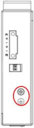 Figure 4 — The grounding screw on the switch
Connecting to a Power Source
The switch can be powered by two power supplies (input range 48 to 58 V DC). Insert the positive and negative wires (AWG 14-26) into V+ and V- contact on the terminal block and tighten the wire-clamp screws to prevent the wires from being loosened.


