
D-Link DIS-100G-8W Industrial Unmanaged
Quick Installation Guide
Package Contents
Open the shipping carton of the switch and carefully unpack its contents. The carton DIS-100G-8W switch
- DC power terminal block
- Wall mounting kit
- DIN-Rail mounting kit
- Quick Installation Guide should contain the following items:
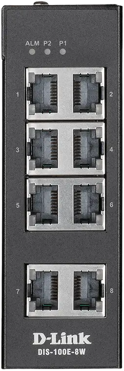
Hardware Overview
Interfaces
| Interface | Description |
| Ports 1-8 | 1000Base-T ports |
LED Indicators
| LED | Status | Description |
| ALM | On red | Power failure alarm occurs. |
| Off | No power failure alarm. | |
| P1 | On green | P1 power line has power. |
| Off | P1 power line is disconnected or does not have a power supply. | |
| P2 | On green | P2 power line has power. |
| Off | P2 power line is disconnected or does not have a power supply. | |
| Link/Act (Ports 1-8) | On green | Ethernet link is up. |
| Blinking green | Ethernet link is up and there is traffic detected. | |
| Off | Ethernet link is down. | |
| Speed (Ports 1-8) | On yellow | 1000 Mbps connection is detected. |
| Off | No link or 10/100 Mbps connection is detected. |
DIP Switches
| Pin № | State | Description |
| Pin 1 | ON | To enable broadcast storm rate limit. |
| OFF | To disable the broadcast storm rate limit. | |
| Pin 2 | ON | To enable the power alarm. |
| OFF | To disable the power alarm. |
Hardware Installation
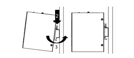
DIN Rail Mounting
Mounting steps:
- Screw the DIN-Rail bracket on with the bracket and screws in the accessory kit.
- Hook the unit over the DIN-Rail.
- Push the bottom of the unit towards the DIN-Rail until it snaps into place
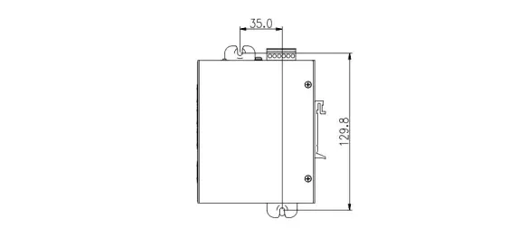
Wall Mounting
Screw on the wall-mount plate with the plate and M4 screws in the accessory kit.

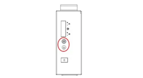
Grounding the Switch
Use the following instructions to ground the switch. Please complete these steps before powering on the switch.
- Remove the grounding screw from the switch and place the grounding cable lug ring on top of the grounding screw opening. Insert the grounding screw back into the
- grounding screw opening and use a screwdriver to tighten the grounding screw, securing the grounding cable to the switch.
- Attach the terminal lug ring at the other end of the grounding cable to an appropriate grounding source.
- Verify that the connection between the grounding connector on the switch and the grounding source is secure.
Connecting to a Power Source
The switch can be powered by two power supplies (input range 12 to 58 V DC). Insert the positive and negative wires (AWG 14-26) into V+ and V- contact on the terminal block and tighten the wire-clamp screws to prevent the wires from being loosened.
Alarm Relay Connecting
The alarm relay output contacts are in the middle of the DC terminal block connector shown in the figure below. By inserting the wires and setting the DIP switch of the respective Port Alarm to “ON”, the relay output alarm will detect any port failures, and form a short circuit. The alarm relay out is “Normal Open”.