Xiamen Tenia Lighting Electrical DNA042BU3-ZB-600-P LED Dimmer Switch
SPECIFICATION
| Model No. | DNA042BU3-ZB-600 -P |
| Rated Voltage | 120V~ |
| Rated Frequency | 60Hz |
| Rated Wattage | 600W |
| Load Range | Incandescent:15W-600W |
| LED/CFL:3W-200W | |
| Dimming method | Phase-cut |
| Working Environment | Temperature: 0℃ – 40℃ |
| Humidity:10% R.H. – 90% R.H. | |
| Model Size | 105 mm×44 mm×35mm (L×W×H) |
WARNINGS AND CAUTIONS
- Risk of fire and electrical shock, the dimmer should be installed in accordance with appropriate electrical codes and regulations.
- This product should be use together with an upstream air-switch.
- Turn power off at circuit breaker or fuse and test that power is off before installing.
- After install the dimmer, it is recommended to set the minimum brightness level to make bulbs turn on immediately.
- If you are unsure about any part of these instructions, consult a licensed electrician.
- To reduce the risk of overheating and possible damage to other equipment, do not install to control a receptacle, a motor-operated appliance or a transformer-supplied appliance.
- Use with compatible dimmable LED, CFL bulbs, Incandescent or halogen bulbs only.
- When multiple bulbs are used with one dimmer DO NOT mix bulb types. All bulbs shall be either LE D,CFL or incandescent. Using the same model of each bulb will enhance dimmer performance.
RF EXPOSURE STATEM
ENT
This equipment complies with the FCC RF radiation exposure limits set forth for an uncontrolled environment. This equipment should be installed and operated with a minimum distance of 20cm between the radiator and any part of your body. This equipment meets the exemption from the routine evaluation limits in section 2.5 of RSS-102. It should be installed and operated with a minimum distance of 20cm between the radiator and any part of your body.
IC Information
This device contains licence-exempt transmitter(s) that comply with Innovation, Science and Economic Development Canada’s licence-exempt RSS(s). Operation is subject to the following two conditions:
- This device may not cause interference. and
- This device must accept any interference, including interference that may cause undesired operation of the device.
FCC Information
This device complies with Part 15 of the FCC Rules. Operation is subject to the following two conditions:
- This device may not cause harmful interference, and
- This device must accept any interference received, including interference that may cause undesired operation.
This equipment has been tested and found to comply with the limits for a Class B digital device, pursuant to part 15 of the FCC Rules. These limits are designed to provide reasonable protection against harmful interference in a residential installation. This equipment generates, uses and can radiate radio frequency energy and, if not installed and used in accordance with the instructions, may cause harmful interference to radio communications. However, there is no guarantee that interference will not occur in a particular installation. If this equipment does cause harmful interference to radio or television reception, which can be determined by turning the equipment off and on, the user is encouraged to try to correct the interference by one or more of the following measures:
- Reorient or relocate the receiving antenna.
- Increase the separation between the equipment and receiver.
- Connect the equipment into an outlet on a circuit different from that to which the receiver is connected.
- Consult the dealer or an experienced radio/TV technician for help.
FCC CAUTION
Any changes or modifications to this unit not expressly approved by the manufacture could void the user’s authority to operate the equipment.
Functional parts instructions
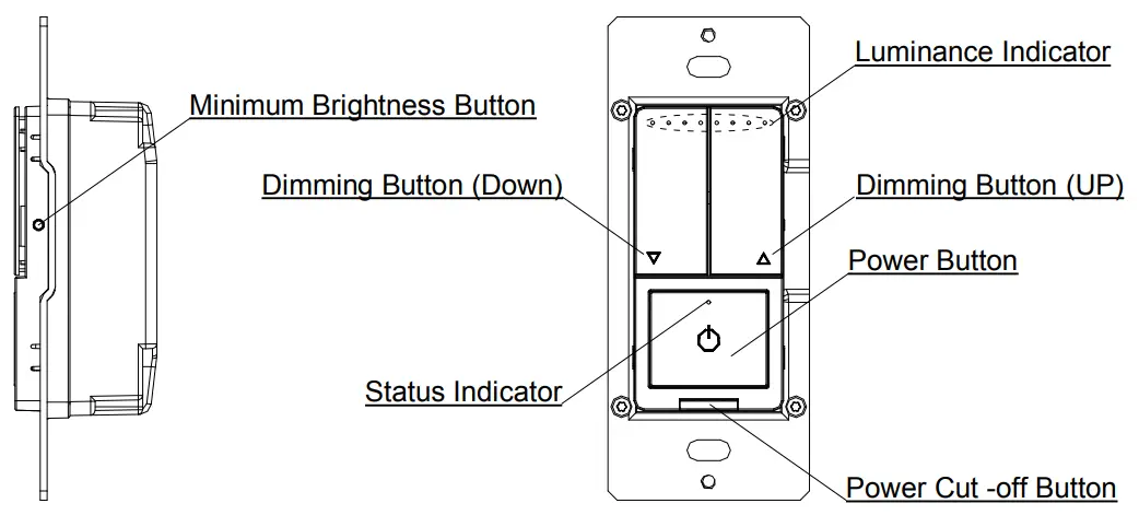
Status Indicator
- Indicator lights red: OFF status.
- Indicator lights white: ON status.
- White Indicator flashing: enter distribution network mode.
Short press: Within 0.5s .
Long press: Over 0.5s.
Continuous short press: Each interval of short press should within 0.3s.
Minimum Brightness Button
- Setting the minimum brightness: There are six minimum brightness levels, short press the button of minimum brightness once can change a minimum brightness level.
Power Button
- Turn on: Short press once when in OFF.
- Turn off: Short press once when in ON.
- Distribution network mode: when the light is on, press 5 times continuously. After the status indicator flashes (On and off once every 2 seconds), the mobile phone can connect the dimmer (if not connected, exit the distribution network modeafter3minutes).
- Short press the power button six times to set the ideal minimum brightness when in ON status.
- Short press the power button eight times to set the ideal maximum brightness when in ON status.
- Continuous short press ten times and the status indicator flash three times to restore the factory default settings, the default brightness is the maximum brightness.
Dimming Button (UP)
- Brightness increase: Short press the dimming button(UP)once can increase a level of brightness when in ON status.
- Brightness increase continuous: Long press the dimming button(UP) can continuous to increase the brightness until reach the maximum brightness.
- Quickly to full brightness: Continuous short press two times when in ON/OFF status to turn quickly to the maximum brightness
Dimming Button (Down)
- Brightness decrease: Short press the dimming button(Down)once can decrease a level of brightness when in ON status.
- Brightness decrease continuous: Long press the dimming button(Down) can continuous to decrease the brightness until reach the minimum brightness.
- Quickly to minimum brightness: Continuous short press two times when in ON/OFF status to turn quickly to the minimum brightness.
Power Cut -off Button
- Put in the power cut-off button to connect the power.
- Put out the power cut-off button to cut off the power.
Luminance Indicator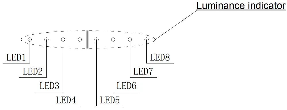
Luminance Indicator Table
| Item | Luminance Level | Luminance Indicator |
| 1 | Luminance Level 1-5 | LED 1 normally on |
| 2 | Luminance Level 6-10 | LED 1~LED 2 normally on |
| 3 | Luminance Level 11-15 | LED 1~LED 3 normally on |
| 4 | Luminance Level 16-20 | LED 1~LED 4 normally on |
| 5 | Luminance Level 21-25 | LED 1~LED 5 normally on |
| 6 | Luminance Level 26-30 | LED 1~LED 6 normally on |
| 7 | Luminance Level 31-35 | LED 1~LED 7 normally on |
| 8 | Luminance Level36-40 | LED 1~LED 8 normally on |
Parts Information
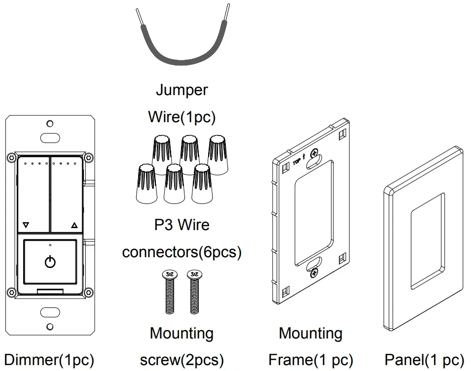
Tools needed to install your Dimmer
| Φ3mm Slotted Screwdriver | Φ5mm Philips Screwdriver | Electrical Tape | Cutters |
| Pliers | Test Pencil | Ruler | – |
Installation and testing
- Step 1
 WARNING: To avoid fire and electrical shock, TURN
OFF POWER at circuit breaker or fuse and test that power is off before wiring. - Step 2 Removing existing switch: Remove existing wall plate and switch mounting screws. Carefully pull switch from wall box, identify and take out the wires attached to the switch, then remove the switch. DO NOT remove wires which are taken out from the switch at this time.(If new configuration is without this step)
- Step 3 Identifying your wiring application
NOTE: If the wiring in the wall box does not resemble any of these configurations, consult an electrician. - Single-Pole

- Line (Hot)
- Neutral
- Ground
- Load
- 3-Way
- Line or Load (See note below)
- Neutral
- Ground
- Traveler 1
- Traveler 2
- Please note that for 3-way application, there have a power cord from the original switch be a different color (Black) or marked Common. Finding this power cord from both the dimmer’s junction box and 3-way junction box and marking as common (live or load).
- Step 4 Typical wiring application
Power supply mode: Live wire or Neutral and Live wire. (Note: If there is Neutral and Live wire condition, please connect to
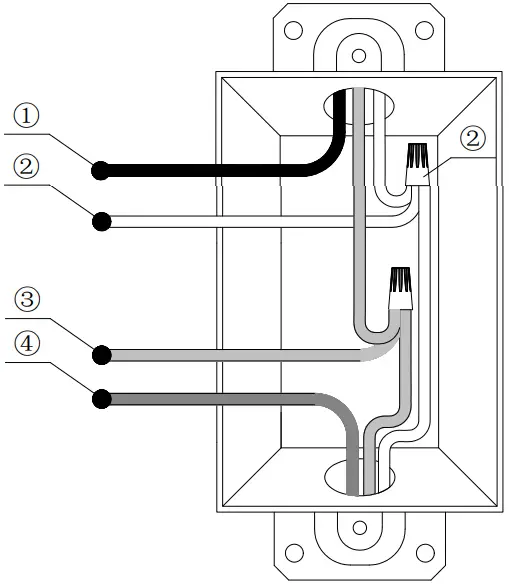
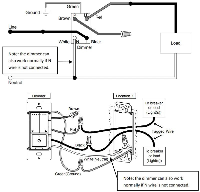
Neutral and Live wire for better compatibility.) - Step 4a Single-Pole
Wiring scheme 1
Location 1 wiring:- Connect the green wire on the dimmer with the green or bare copper ground wire on the wall box and tighten it by screwing the P3 wiring nut.
- Connect the black wire on the dimmer with the live wire of the circuit breaker or load wire and tighten it by screwing the P3
wiring nut. - Connect the white wire on the dimmer with the neutral wire, and tighten it by screwing the P3 wiring nut. (Note: the dimmer can
also work normally if N wire is not connected.)
Connect the red wire on the dimmer with the live wire of the circuit breaker or load wire and tighten it by screwing the P3 wiring nut. - Protect the remaining brown wire on the dimmer by screwing the P3 wiring nut
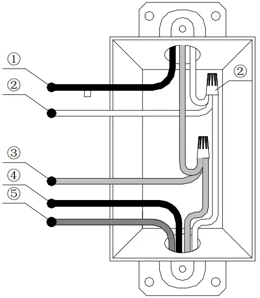
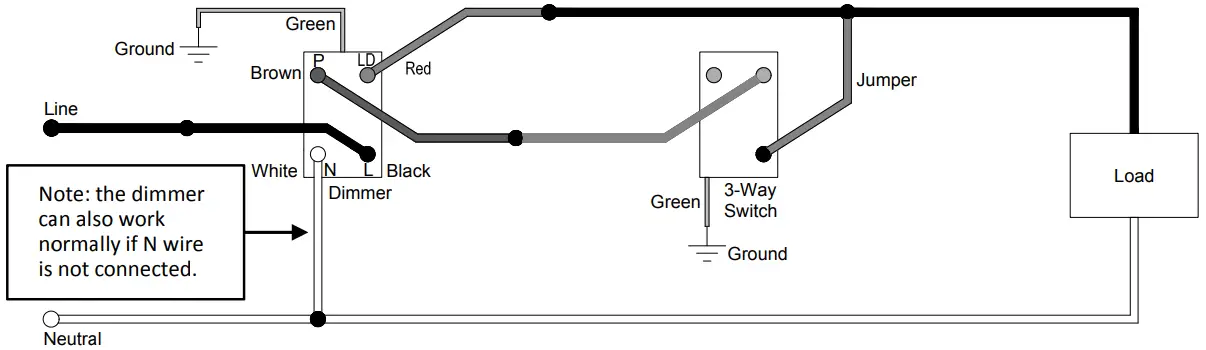
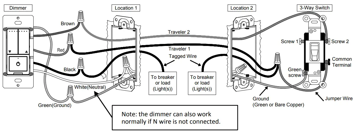
- Step 4b-1 3-Way(3-way Switch)
Wiring scheme 2

- Location 1 wiring:
- Connect the green wire on the dimmer with the green or bare copper ground wire on the wall box and tighten it by screwing the P3 wiring nut.
- Connect the black wire on the dimmer with the live wire of the circuit breaker or load wire and tighten it by screwing the P3 wiring nut.
- Connect the white wire on the dimmer with the neutral wire, and tighten it by screwing the P3 wiring nut. (Note: the dimmer can also work normally if N wire is not connected.)
- Connect the brown wire on the dimmer with Traveler 2 and
tighten it by screwing the P3 wiring nut. - Connect the red wire on the dimmer with Traveler 1 and tighten it by screwing the P3 wiring nut.
- Location 2 wiring:
- Connect Traveler 2 with Screw 1 or Screw 2 of the 3-way Switch.
- Connect the 3-way Switch Common Terminal with the Jumper wire, then connect Traveler 1 with the Jumper wire, as well a the live wire of the circuit breaker or load wire, and tighten it by screwing the P3 wiring nut.
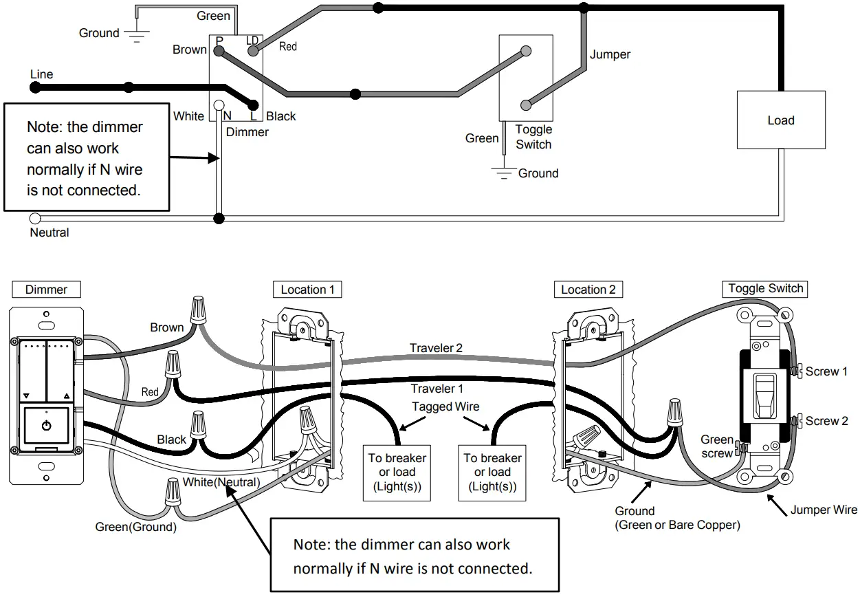
- Step 4b-2 3-Way(Toggle Switch)
Wiring scheme 2
- Location 1 wiring:
- Connect the green wire on the dimmer with the green or bare copper ground wire on the wall box and tighten it by screwing the P3 wiring nut.
- Connect the black wire on the dimmer with the live wire of the circuit breaker or load wire and tighten it by screwing the P3 wiring nut.
- Connect the white wire on the dimmer with the neutral wire, and tighten it by screwing the P3 wiring nut. (Note: the dimmer can also work normally if N wire is not connected.)
- Connect the brown wire on the dimmer with Traveler 2andtighten it by screwing the P3 wiring nut.
- Connect the red wire on the dimmer with Traveler 1andtightenit by screwing the P3 wiring nut.
- Location 2 wiring:
- Connect Traveler 2 with Screw 1 of the Toggle Switch.
- Connect Screw 2 of the Toggle switch with the Jumper wire, then connect Traveler 1 with the Jumper wire, as well as the live wire of the circuit breaker or load wire, and tighten it by screwing the P3 wiring nut.
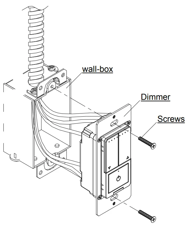
- Step 5 Installing dimmer
- Carefully position all wires inside the wall-box, leaving enough space to insert the dimmer and tighten with the matched screws.

- Carefully position all wires inside the wall-box, leaving enough space to insert the dimmer and tighten with the matched screws.
- Step 6 Install the panel
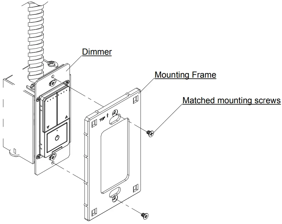
- Step 6a Split panel
- Install the mounting frame on the dimmer and secure it with the supporting mounting screws.

- Put the panel and mounting frame together, press gently to make sure it is be installed firmly.

- Install the mounting frame on the dimmer and secure it with the supporting mounting screws.
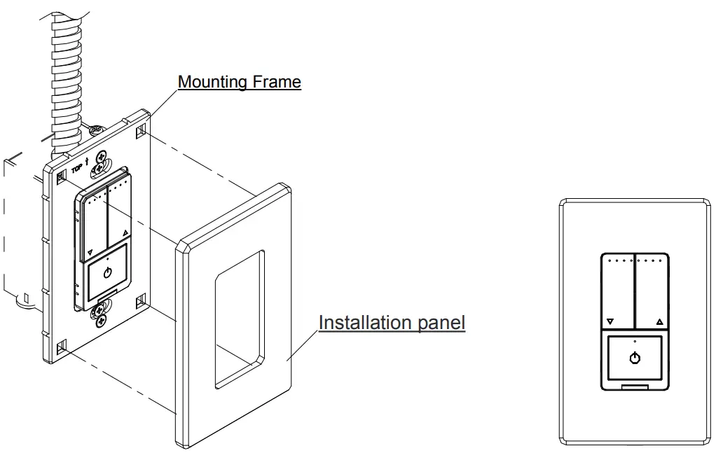
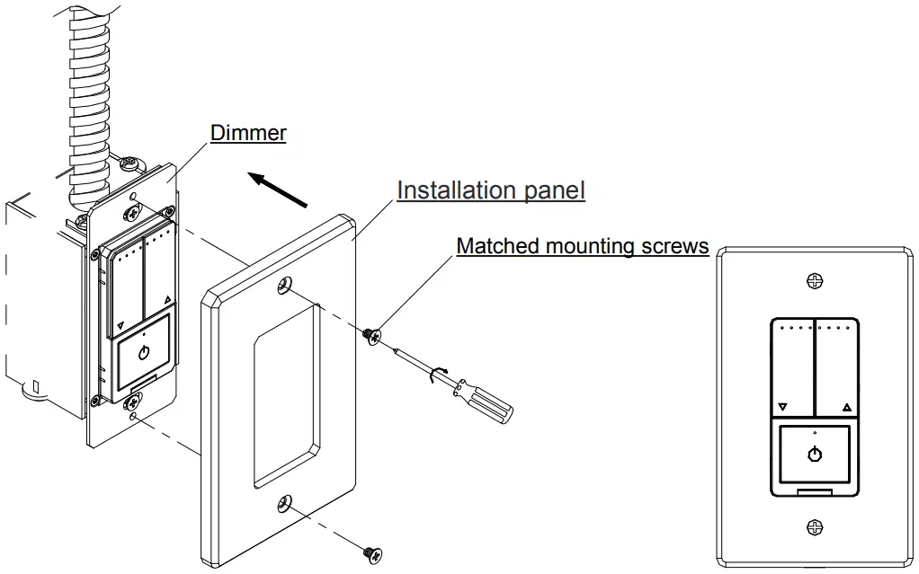
- Step 6b Integrated panel
- Place the panel on the mounted dimmer and secure it with the
matching mounting screws.
- Place the panel on the mounted dimmer and secure it with the
Using instruction
Short press: within 0.5 second. Long press: more than 0.5 second.
Continuous short press: The interval between two short presses is less than 0.3 second.
Function instruction
Table 1 Single – Pole Function table
| Function | Dimmer Operation Way | Dimmer Operation | APP Operation |
| Distribution network mode | Continuous short press power button 5 times | √ | × |
| ON/OFF | Short press the power button once | √ | √ |
| Time switch on/off | NOT | × | √ |
| Dimming | Short or long press the power button UP/DOWN | √ | √ |
| Quickly turn to the maximum brightest | Continuous short press the dimming Button (UP) twice | √ | √ |
| Quickly turn to the minimum brightest | Continuous short press the dimming Button (DOWN) twice | √ | √ |
| Setting the maximum brightness | Continuous short press the power button eight times | √ | × |
| Setting the minimum brightness | Short press minimum brightness button | √ | × |
| Continuous short press the power button six times | √ | × | |
| Restore factory Settings | Continuous short press the power button ten times | √ | × |
| Shared device | NOT | × | √ |
| group control | NOT | × | √ |
Table2 3 – way Function table
| Function | Dimmer Operation Way | Dimmer Operation | 3-way Switch or Toggle Switch Operation | APP Operation |
| Distribution network mode | Continuous short press power button 5 times | √ | × | × |
| ON/OFF | Short press the power button once | √ | √ | √ |
| Time switch on/off | NOT | × | × | √ |
| Dimming | Short or long press the power button UP/DOWN | √ | × | √ |
| Quickly turn to the maximum brightest | Continuous short press the dimming Button (UP) twice | √ | × | √ |
| Quickly turn to the minimum brightest | Continuous short press the dimming Button (DOWN) twice | √ | × | √ |
| Setting the maximum brightness | Continuous short press the power button eight times | √ | × | × |
| Setting the minimum brightness | Short press minimum brightness button | √ | × | × |
| Continuous short press the power button six times | ||||
| Restore factory Settings | Continuous short press the power button ten times | √ | × | × |
| Shared device | NOT | × | × | √ |
| group control | NOT | × | × | √ |
Priority
- On line operation can stop the mobile App operation; when on line operating, App can’t operate.
Troubleshooting
| Problems | Possible Cause | Solution |
| Lights flickering | Lamp has a bad connection. | Reconnect and fix the wires. |
| One dimmer been connected to multiple types bulbs, incur interference and cause flicker. | Change bulbs to same type. | |
| Abnormal | Put the power cut-off button out and cut off the power, then put the power cut-off button in and connect the power on again. | |
| LED and CFL flickers at low end of dimming range. | Load compatibility is not good. | Turn up lamp minimum brightness properly. |
| Lamps can’t be turn on | Circuit breaker has tripped. | Turn power on |
| Fuse burn out | Change fuse | |
| Lamp burned out | Change lamp | |
| Lamp neutral connection is not wired | Reconnect the lamp neutral | |
| Lights out of control or unable to connect to the network | abnormal | Pull out the power cut-off switch and disconnect the power supply; Insert the power cut-off switch and turn on the power again; |
| The dimmer cannot be operated in 3-way connection | wiring connections error or disconnected | Check the wiring |
| 3-way switch is abnormal | Replace the 3-way switch |
Distribution network
Continuous short press:
The interval between two short presses is less than 1 second
- Network mode: when the light is on, press the on key continuously for 5 times. After the status indicator blinks quickly (on and off once every 2 seconds), the phone can be connected to the dimmer. (if it is not connected, exit the network mode after 3 minutes).
- Supports Amazon Echo Plus and Philips Hue control.
Mobile app operation
- Step 1 Download the ‘Smart Life’App
- Use your mobile device to scan the QR code below or search for “Smart Life” in the App Store or Google play to download and install the app

- Use your mobile device to scan the QR code below or search for “Smart Life” in the App Store or Google play to download and install the app
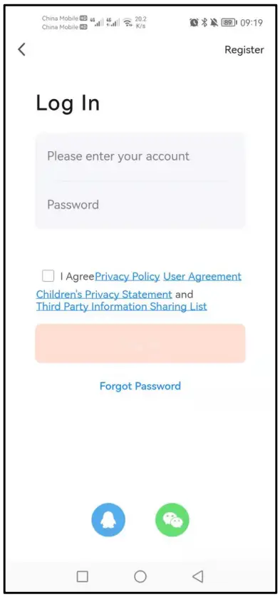
- Step 2 Register an account and Login
- Open the Smart Life app, click Register to create an account and login.

- Open the Smart Life app, click Register to create an account and login.
- Step 3 Add the ZigBee gateway
- Click on the top right
 , click Add Device;
 - Click Gateway Control and then click
 ,to enter the device connection interface.
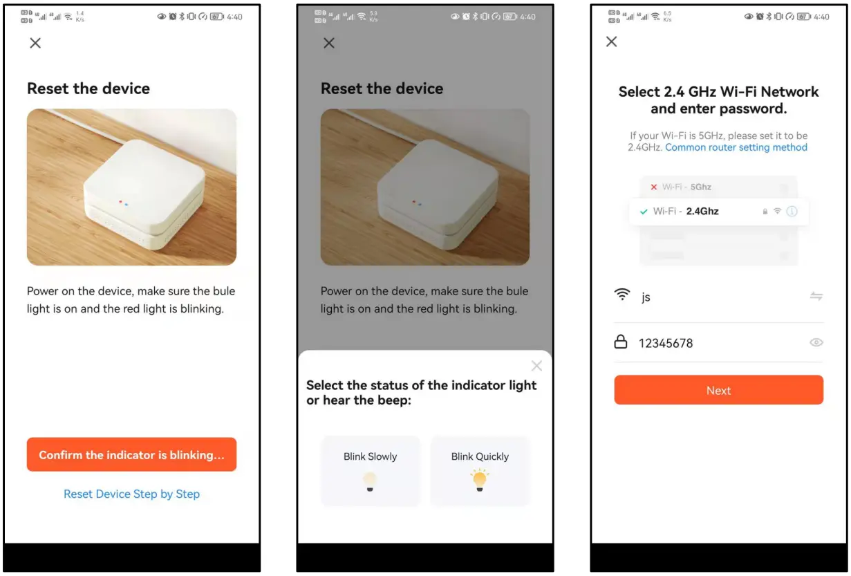
- Make sure the App control indicator LED1 is blinking, click Confirm the indicator is blinking…,click
 。
。 - Enter your home Wi-Fi password, click Next, and wait for the connection.

- Click on the top right
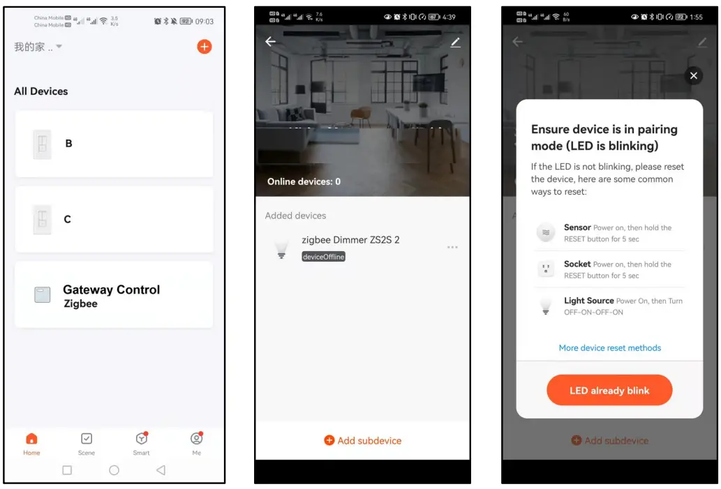
- Step 4 Add dimmer
- Distribution network mode: when the light is on, press switch continuously for 5 times. After the status indicator blinks quickly (on and off once every 2 seconds), the phone can be connected to the dimmer. (if it is not connected, exit the network mode after 3 minutes).
- Click
 ,Click Add sub-device, Click LED already blink, and wait for connection.
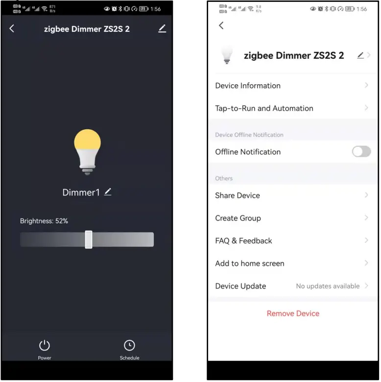
- Step 5 Use the phone App to control dimmer
- Click
 ,control the light on and off function of the dimmer.
 - Slide
 ,and then dimming.
- Click
 ,to set the timer light on and off function of the dimmer.
 - Add timing and save.

- After the dimmer is connected, it can be shared with multiple people, that is, one dimmer can be controlled by multiple apps.
- Click the upper right corner to
 ,enter the device details interface.
 - Click Share Device, to enter the Device sharing interface and add family members.

- Click

 , click Add Device;
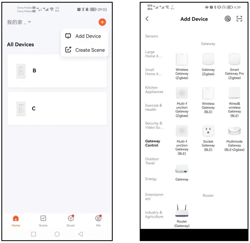
 。
。
 ,control the light on and off function of the dimmer.
 ,and then dimming.
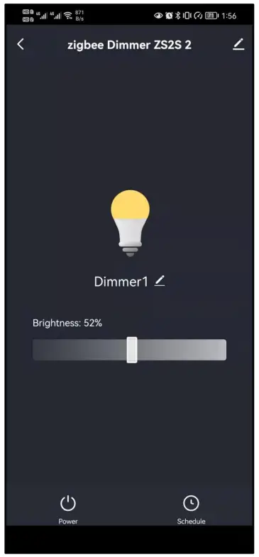
 ,to set the timer light on and off function of the dimmer.
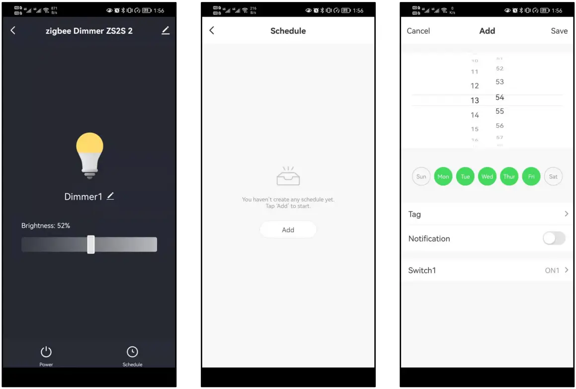
 ,enter the device details interface.