![]()
Installation Instructions
LED Dimmer Switch
Works with DIMMABLE LEDzx, CFL, Incandescent, and halogen bulbs
| Model No. | DNA042DU2-W-600-P |
| Rated Voltage | 120V |
| Rated Frequency | 60Hz |
| Rated Wattage | 600W |
| Load Range | Incandescent:15W-600W |
| LED/CFL:3W-200W | |
| Dimming method | Phase-cut |
| Working Environment | Temperature: 0℃ – 40℃ |
| Humidity:10% R.H. – 90% R.H | |
| Model Size | 105 mm×44 mm×31mm (L×W×H) |
WARNINGS AND CAUTIONS
- Risk of fire and electrical shock, the dimmer should be installed in accordance with appropriate electrical codes and regulations.
- This product should be used together with an upstream air switch.
- Turn the power off at the circuit breaker or fuse and test that power is off before installing.
- After installing the dimmer, it is recommended to set the minimum brightness level to make bulbs turn on immediately.
- If you are unsure about any part of these instructions, consult a licensed electrician.
- To reduce the risk of overheating and possible damage to other equipment, do not install to control a receptacle, a motor-operated appliance, or a transformer-supplied appliance.
- Use with compatible dimmable LED, CFL bulbs, Incandescent or halogen bulbs only.
- When multiple bulbs are used with one dimmer DO NOT mix bulb types. All bulbs shall be either LED, CFL, or incandescent. Using the same model of each bulb will enhance dimmer performance.
RF EXPOSURE STATEMENT
- This equipment complies with the FCC RF radiation exposure limits set forth for an uncontrolled environment. This equipment should be installed and operated with a minimum distance of 20cm between the radiator and any part of your body.
FCC Information
- This device complies with Part 15 of the FCC Rules. Operation is subject to the following two conditions:
(1) This device may not cause harmful interference.
(2) This device must accept any interference received, including interference that may cause undesired operation.
Note1: This equipment has been tested and found to comply with the limits for a Class B digital device, pursuant to part 15 of the FCC Rules. These limits are designed to provide reasonable protection against harmful interference in a residential installation. This equipment generates, uses, and can radiate radio frequency energy and, if not installed and used in accordance with the instructions, may cause harmful interference to radio communications. However, there is no guarantee that interference will not occur on a particular installation. If this equipment does cause harmful interference to radio or television reception, which can be determined by turning the equipment off and on, the user is encouraged to try to correct the interference by one or more of the following measures:
- Reorient or relocate the receiving antenna.
- Increase the separation between the equipment and receiver.
- Connect the equipment into an outlet on a circuit different from that to which the receiver is connected.
- Consult the dealer or an experienced radio/TV technician for help.
Note2: Any changes or modifications to this unit not expressly approved by the manufacturer could void the user’s authority to operate the equipment.
FCC CAUTION
- Any changes or modifications to this unit not expressly approved by the manufacturer could void the user’s authority to operate the equipment.
Functional parts instructions
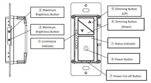
- Status Indicator
• Indicator lights red: OFF status.
• Indicator lights green: ON status.
• Green light flashing: enter distribution network mode.
Short press: Within 0.5s.
Long press: Over 0.5s.
Continuous short press: Each interval of the short press should be within 0.3s. - Maximum Brightness Button
• Setting the maximum brightness: There are six maximum brightness levels, short press the button of maximum brightness once can change a maximum brightness level. - Minimum Brightness Button
• Setting the minimum brightness: There are six minimum brightness levels, short press the button of minimum brightness once can change a minimum brightness level. - Power Button
• Turn on: Short press once when in OFF.
• Turn off: Short press once when in ON.
• distribution network mode: when the light is on, press the on key 5 times continuously. After the status indicator flashes (once in 2 seconds), the mobile phone can connect to the dimmer. After the distribution network is successful, (if not connected, exit the distribution network mode after 3 minutes).
Note:
• When entering into distribution network mode, turn on the wifi and Bluetooth of the mobile phone at the same time, so that the distribution network mode can be configured quickly.
• In case of wi-fi disconnection, under the condition of normal wireless Internet access of the mobile phone, turn on the Bluetooth of the mobile phone, and after 5min, the mobile phone APP can control the dimmer.
• Short press the power button six times to set the ideal minimum brightness when in ON status.
• Short press the power button eight times to set the ideal maximum brightness when in ON status.
• Continuous short press ten times and the status indicator flashes three times to restore the factory default settings when in the maximum brightness status. - Dimming Button (UP)
• Short press the dimming button once can increase the level of brightness when in ON status.
• Long pressing the dimming button can continuous increase the brightness until release or reach the maximum brightness.
• Continuous short press two times when in ON/OFF status to turn quickly to the maximum brightness. - Dimming Button (Down)
• Short pressing the dimming button once can decrease the level of brightness when in ON status.
• Long press the dimming button can continue to decrease the brightness until release or reach the minimum brightness.
status to turn quickly
• Continuous short press two times when in ON/OFF to the minimum brightness. - Power Cut-off Button
• Put in the power cut-off button to connect the power.
• Put out the power cut-off button to cut off the power. - Luminance Indicator
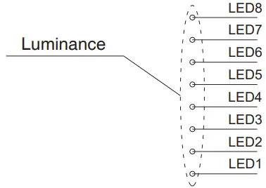
| Item | Luminance Level | Luminance Indicator |
| 1 | Luminance Level 1-5 | LED 1 normally on |
| 2 | Luminance Level 6-10 | LED 1 |
| 3 | Luminance Level 11-15 | LED 1 |
| 4 | Luminance Level 16-20 | LED 1 |
| 5 | Luminance Level 21-25 | LED 1 |
| 6 | Luminance Level 26-30 | LED 1 |
| 7 | Luminance Level 31-35 | LED 1 |
| 8 | Luminance Level 36-40 | LED 1 |
Switch Operation
- Turn on: Switch on when the light is off.
- Turn off: Switch on when the light is on.
Parts Information
 Tools need to install the dimmer
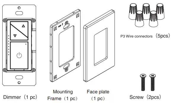 Tools need to install the dimmer
| ∅ 5mm Philips Screwdriver | Test Pencil |
| Electrical Tape | Plier |
| Cutter | Ruler |
Installation
Step 1 WARNING: To avoid fire and electrical shock, TURN PFF POWER at the circuit breaker or fuse and test that power is off before wiring.
Step 2 Remove the screws installed on the existing panel and switch, carefully pull out the switch from the wall box, identify and remove the power cord attached to the switch, and the switch, do not remove the power cord detached from the switch. (This step is not required for new configuration installation.)
Step 3 Identify the power cord type
Note: If the power cord in the wall box is different from the following layouts, please consult an electrician.
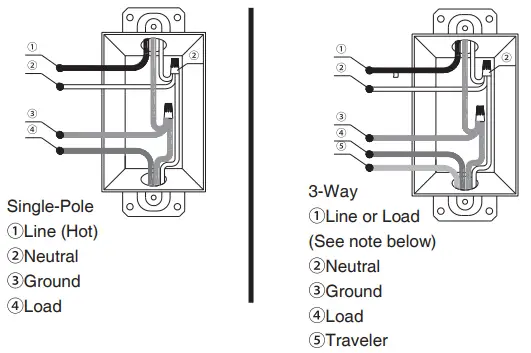
IMPORTANT: For 3-Way applications, note that one of the screw terminals from the old switch being removed will usually be a different (Black)or labeled Common (Line or Load)in both the dimmer wall box and 3-way wall box.
Step 4 Typical wiring application
Step 4a Single-Pole
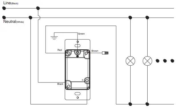 |  |
- Connect the green power cord with the ground power cord of the wall box, and tighten it with a P3 wire nut.
- Connect the black power cord with the line power cord of the wall box, and tighten with a P3 wire nut.
- Connect the white line on the dimmer with the zero line, and tighten with a P3 wire nut.
- Connect the red power cord with the neutral power cord of the wall box, and tighten withP3 a wire nut.
- Screw the remaining brown wire on the dimmer with a P3 wire nut for protection.
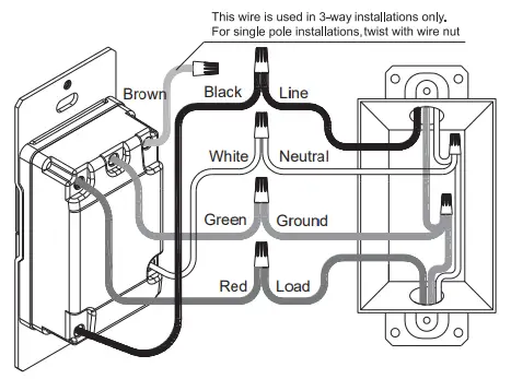
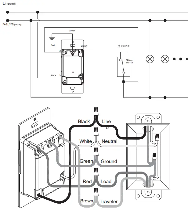
Step 4b 3-Way
Connection way 1 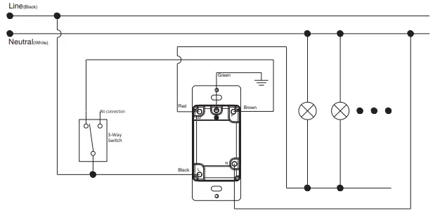
Connection way 1
 Connect the green power cord with the ground power cord of the wall box, and tighten with a P3 wire nut.
- Connect the black power cord with the line power cord of the wall box, and tighten with a P3 wire nut.
- Connect the red power cord with the load power cord of the wall box, and tighten with a P3 wire nut.
- Connect the white power cord with the neutral power cord of the wall box, and tighten with a P3 wire nut.
- Connect the brown power cord with the traveler power cord of the wall box, tighten it with a P3 wire nut
Step 5 Installing dimmer - Carefully position all wires inside the wall box, leaving enough space to insert the dimmer and tighten it with the matched screws.
 Connect the green power cord with the ground power cord of the wall box, and tighten with a P3 wire nut.
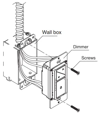
Step 6
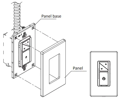
Step 6a Separated plate
- Installing the panel base on the dimmer and tightening with the matched screws.
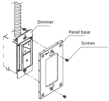
- Put the panel and panel base together, and press gently to make sure it is installed firmly.
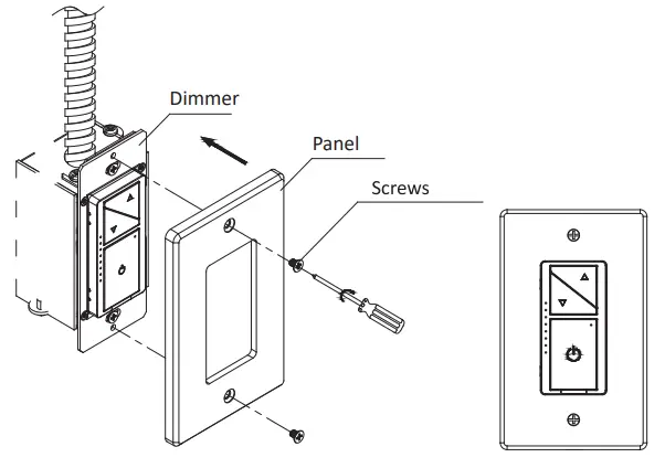
Step 6b One-piece panel
- Place the panel on the installed dimmer and fix it firmly with the matching mounting screws.
Using instruction
Short press: within 0.5 second
Long press: more than 0.5 second
Continuous short press: The interval between two short presses is less than 0.3 second
Function instruction
Table 1 Single-Pole Function table
| Function | Dimmer Operation Way | Dimmer Operation | APP Operation |
| Distribution network mode | Continuous short press the power button 5 times | × | × |
| ON/OFF | Short press the power button once | √ | √ |
| Time switch on/off | NOT | × | √ |
| Dimming | Short or long-press the power button UP/DOWN | √ | √ |
| Quickly turn to the maximum brightest | Continuous short press the dimming Button (UP) twice | √ | √ |
| Quickly turn to the minimum brightest | Continuous short press the dimming Button (DOWN) twice | √ | √ |
| Setting the maximum brightness | Short press the maximum brightness button |
√ |
√ |
| Continuous short press the power button eight times | |||
| Setting the minimum brightness | Short press the minimum brightness button |
√ |
√ |
| Continuous short press the power button six times | |||
| Restore factory Settings | Continuous short press the power button ten times | √ | × |
| Shared device | NOT | × | √ |
| group control | NOT | × | √ |
Table2 3-way Function table
| Function | Dimmer Operation Way | Dimmer Operation | Power-off Operation | APP Operation |
| Distribution network mode | Continuous short press the power button5 times | × | × | × |
| ON/OFF | Short press the power button once | √ | √ | √ |
| Time switch on/off | NOT | × | × | √ |
| Dimming | Short or long-press the power button UP/DOWN | √ | × | √ |
| Quickly turn to the maximum brightest | Continuous short press the dimming Button (UP) twice | √ | × | √ |
| Quickly turn to the minimum brightest | Continuous short press the dimming Button (DOWN) twice | √ | × | √ |
|
Setting the maximum brightness | Short press maximum brightness button | √ | × | √ |
| Continuous short press the power button eight times | ||||
| Setting the minimum brightness | Short press the minimum brightness button | √ | × | √ |
| Continuous short press the power button six times | ||||
| Restore factory Settings | Continuous short press the power button ten times | √ | × | × |
| Shared device | – | × | × | √ |
| group control | – | × | × | √ |
Priority
- The online operation can stop the mobile App operation; when online operating, The app can’t operate.
Troubleshooting
| Problems | Possible Cause | Solution |
| Lights flickering | The lamp has a bad connection. | Reconnect and fix the wires. |
| One dimmer has been connected to multiple types of bulbs, incurring interference and causing flicker. | Change bulbs to the same type. | |
| Abnormal | Put the power cut-off button out and cut off the power, then put the power cut-off button in and connect the power on again. | |
| LED and CFL flickers at the low end of dimming range. | Load compatibility is not good. | Turn up lamp minimum brightness properly. |
| Lamps can’t be turned on | The circuit breaker has tripped. | Turn power on |
| Fuse burn out | Change fuse | |
| Lamp burned out | Change lamp | |
| Lamp neutral connection is not wired | Reconnect the lamp neutral | |
| Lights out of control or unable to connect to the network | abnormal | Pull out the power cut-off switch and disconnect the power supply; Insert the power cut-off switch and turn on the power again; |
Mobile App operation
Step 1 Download the Doodle Smart App
- Arrange to download the Doodle Smart App by scanning the QR code below
 https://smartapp.tuya.com/tuyasmart
- Either head to the App Store or major Android App markets to search for “Doodle Intelligence” to download an App, anyway.
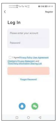
Step 2 Create a Doodle Smart App account and log in
- Invest in something to open the Doodle Smart App, click Register, sign up for an account and log in.
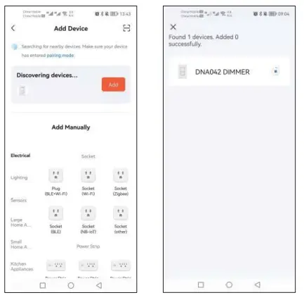
Step 3 Add a dimmer
- Click on the top right
 , Add Device;
 - Click Lighting and then click
 to enter the device connection interface.
 , Add Device;
 to enter the device connection interface.
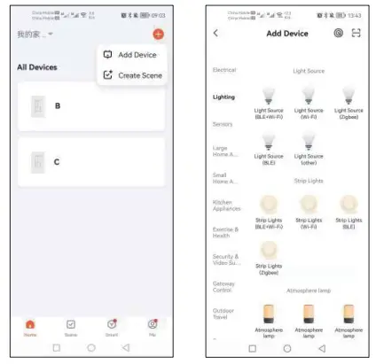
Step 4 Connect the mobile phone
- According to the network mode, when the phone is on, you press the on key five times or hold down the key for a long time, and the status indicator blinks blue to connect the phone to a dimmer (if it is not connected, you log out of the network mode three minutes later).
Note:
- Buy a way to access the Internet, by switching on your phone’s Wi-Fi and Bluetooth at the same time.
- Smartphone APP controls the dimmer 5 minutes later when the phone’s Bluetooth is switched on during a Wi-Fi disconnect.
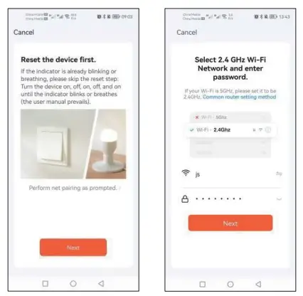
Step 4a Rapid distribution network
- Put your phone’s Wi-Fi and Bluetooth on at the same time to automatically scan for internet-enabled devices.
- Click Add,
 and wait for connecting.
Step 4b Normal distribution network
- To confirm that the App control indicator LED1 is blinking, Click Next.
- Buy a ticket to enter your home Wi-Fi password, click Next, and wait for the connection
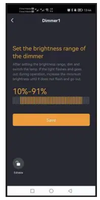
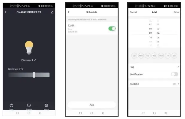
Step 5 Use the mobile phone App to control the dimmer
- Click to
 control the light on and off function of the dimmer;
 - Slide the
 for dimming;
 control the light on and off function of the dimmer;
 for dimming;
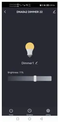
- clicking the
 , enter the interface for setting the dimmer’s brightness range.
 - Set the minimum brightness and maximum brightness of the lamp controlled by the dimmer and save.
- clicking the
 set the dimmer to switch the light on and off at a certain time;
 - Virtual gateway Adds a timing and saves it.
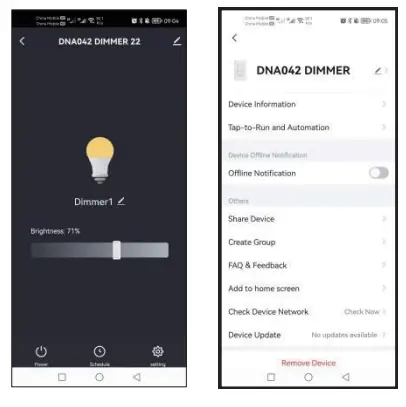
- Dimmer can be shared between multiple people once connected, meaning one dimmer can be controlled by multiple apps.
- Click the
 upper right corner to enter the device details interface.
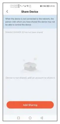
 - The queue to enter the Device sharing interface by clicking Share Device.
- Buy a shared account by clicking Add Sharing.
Supports Amazon Alexa and Google Home voice controls
● For Amazon Alexa
☆Alexa,turn on <device name>
☆ Alexa,turn off <device name>
☆ Alexa,set <device name> to percent
☆ Alexa,brighten/increase <device name>
☆ Alexa,dim/decrease <device name>
● For Google Home
☆ Hey Google,turn on <device name>
☆ Hey Google,turn off <device name>
☆ Hey Google,is <device name> on/off?
☆ Hey Google,brighten/increase <device name>
☆ Hey Google,Dim/Brighten <device name> by 50%
FCC Statement
This equipment has been tested and found to comply with the limits for a Class B digital device, pursuant to part 15 of the FCC Rules. These limits are designed to provide reasonable protection against harmful interference in a residential installation. This equipment generates, uses, and can radiate radio frequency energy and, if not installed and used in accordance with the instructions, may cause harmful interference to radio communications. However, there is no guarantee that interference will not occur in a particular installation. If this equipment does cause harmful interference to radio or television reception, which can be determined by turning the equipment off and on, the user is encouraged to try to correct the interference by one or more of the following measures:
• Reorient or relocate the receiving antenna.
• Increase the separation between the equipment and receiver.
• Connect the equipment into an outlet on a circuit different from that to which the receiver is connected.
• Consult the dealer or an experienced radio/TV technician for help.
Caution: Any changes or modifications to this device not explicitly approved by the manufacturer could void your authority to operate this equipment.
This device complies with part 15 of the FCC Rules. Operation is subject to the following two conditions: (1) This device may not cause harmful interference, and (2) this device must accept any interference received, including interference that may cause undesired operation.
RF Exposure Information
This equipment complies with FCC radiation exposure limits set forth for an uncontrolled environment. This equipment should be installed and operated with a minimum distance of 20cm between the radiator and your body.


