EGUANA Evolve ESS AU-13 kWh Home Energy Storage System Owner’s Manual
This manual contains important product information for your Evolve battery energy storage system (BESS). This document is accurate at the time of publishing. Eguana reserves the right to make updates to the product without notice. For the latest Evolve documents, please visit our website at www.eguanatech.com
WARNING! Read this document in its entirety before using this product. Failure to follow instructions or warnings can result in electrical shock, serious injury, or death. Operating the product in a way that it was not intended can also result in permanent damage to the product.
This manual applies to the following energy storage systems:
Evolve ESS AU -13 kWh / -26kWh / -39kWh
Evolve LFP AU -14 kWh / -28 kWh / -42kWh
Evolve 0513
Warranty
The Eguana Evolve includes a 10 year standard warranty with performance pro-rating for the battery modules. Please review the warranty statement included with your product.
IMPORTANT! An internet connection is required in order to make warranty claims for defective battery modules. The Evolve system supports wired and/or wi-fi internet connection options. Please consult your installer regarding your preferred internet connection method.
Safety
Throughout this manual, the following symbols will be used to highlight important information and procedures:
| Symbol | Definition |
| WARNING! A dangerous voltage or other condition exists. Use extreme caution when performing these tasks. | |
 | CAUTION! This information is critical to the safe installation and or operation of the system. Follow these instructions closely. |
 | NOTE: This statement is important. Follow instructions closely |
In case of emergency
In all cases:
If safe to do so, switch off the AC breakers (external to the system) for the system. Contact the fire department or other required emergency response team. Evacuate the area, and if applicable, follow your emergency evacuation plan if others are in proximity to the installed location.
In case of fire:
When safe, use a fire extinguisher suitable for use; including A, B, and C dry chemical fire extinguishers or carbon dioxide extinguishers. Do not use type D extinguishers.
In case of flooding:
Stay out of water if any part of the system or wiring is submerged.
Do not attempt to operate batteries that have been submerged in water even after they have been dried.
In case of unusual noise, smell or smoke:
If safe to do so, ventilate the area.
In case of weather alerts including tornado, hurricane or potentially wind-damaging risk:
The system is capable of automatically generating emergency backup power on loss of grid, however, in the case where winds are potentially threatening to your building structure and safety, it is recommended to shut down your system in advance of, and for the duration of, the extreme weather event, and to return to operation only after it appears safe to do so.
General safety precautions
![]() Important! Never operate the system in a manner not described by this manual.
Important! Never operate the system in a manner not described by this manual.
Only qualified personnel should service this product.
Risks of Fire
- Do not expose the system to temperatures exceeding 45 degrees Celsius.
- Avoid installation in direct sunlight.
- Do not store objects on top of the cabinet.
- Do not obstruct the intake or exhaust of the forced airflow system.
- Do not store combustible objects and corrosive chemicals directly adjacent to the system.
Risks of Shock
![]() WARNING! Hazardous Voltages. The Inverter contains hazardous voltage and energy that may be lethal.
WARNING! Hazardous Voltages. The Inverter contains hazardous voltage and energy that may be lethal.
It may only be installed by qualified personnel who have read this manual and are familiar with its operation and hazards.
Only connect the PCS cabinet to a compatible electrical service as defined in the model specifications. The PCS must be connected to a dedicated branch circuit in the main electrical panel.
Ensure proper electrical grounding in accordance with code requirements.
![]() CAUTION! Both AC and DC voltage sources are terminated inside this equipment. Each circuit must be disconnected before servicing.
CAUTION! Both AC and DC voltage sources are terminated inside this equipment. Each circuit must be disconnected before servicing.
Risks of Damage
The PCS is compatible with the LG Chem battery model EM048126P3S7 only. Do not attempt to connect any other battery to the system.
Do not connect any other loads directly to the battery power bus.
Do not drop, tip, or puncture the cabinet during transport and installation. Visible damage to the cabinet and/or internal components should be reported to the manufacturer immediately.
Do not store this system for periods longer than six months without a battery maintenance charge. This may result in permanent damage to the batteries.
Do not operate the system outside the operating temperature range (-10 to 45C)
Environmental protection

Do not dispose of the system or any of the components within the cabinet. Batteries, electronics, cables, and metal parts are recyclable. Consult your municipal waste management authority to determine required methods of component recycling.
INTRODUCTION
Overview
This manual contains instructions for the operation of the Eguana Evolve™ home energy storage system. This product, when installed, is permanently wired to the home electrical panel.
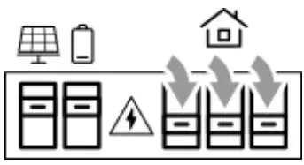
There are two main components as shown below, including the energy storage system (1), and the energy meters installed in the main electrical panel (2). The system may include one or two meters, depending on the solar system that is installed.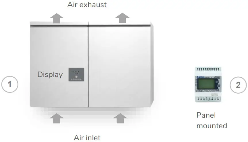
This product is intended to operate in parallel with a utility connected solar PV system, and is designed to manage the consumption of utility and solar energy within the home. The system is capable of providing limited backup power to the home in case of a grid outage, as well as charge batteries from the solar system. A sample diagram below shows a typical layout of an AC coupled solar plus storage system
Your system may be installed in a manner differently than shown above. In addition, in accordance with your local electrical code, your installer may have included dedicated emergency disconnect switches for your battery and solar systems. Consult your system installer regarding the application and installation setup of your specific system. Refer to the Installer Checklist at the end of this document regarding information to be provided to you from your certified system installer.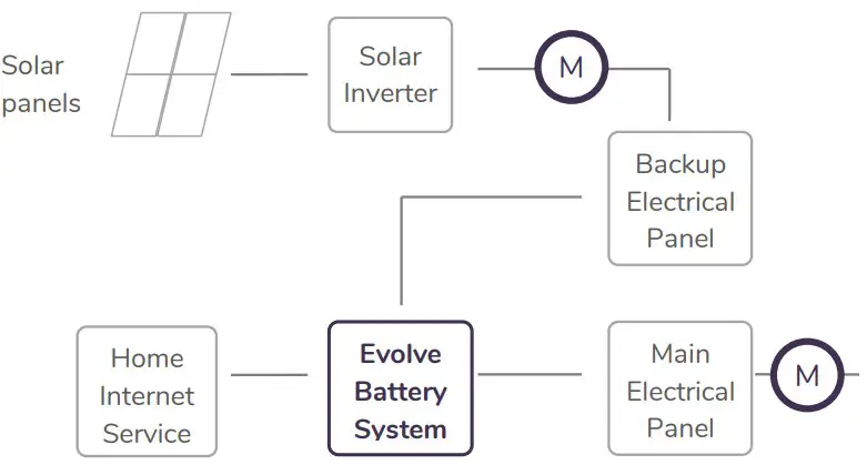
The backup electrical panel shown is a dedicated electrical bus separated from the main electrical bus. While they are shown as two independent panels above, the backup panel may be co-located inside the main switchboard
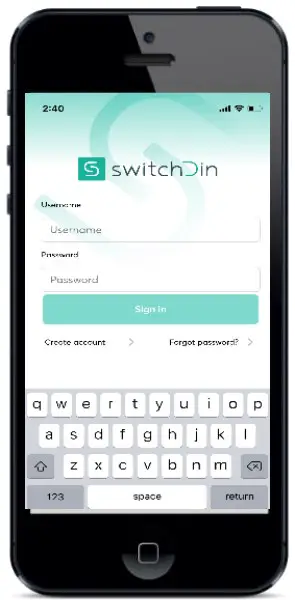
System Monitoring – Account Setup
To view your system online, download the Stormcloud by SwitchDin app (available in IOS & Android) and enter the login credentials provided in the account invitation email issue by your installer. Alternatively, access the monitoring system via web-browser @ https://pwa.switchdin.com/account/login
Operation
The Evolve home energy storage system is fully automated. The EMS will be programmed to connect the system to the grid after AC and DC sources are applied. While the monitoring system provides a complete dashboard of your system’s operating state, the LED display on the front of the battery system can be used to determine its present operating conditions.
LED Display Indicators
The display panel provides indication of the following: Battery status (state of charge) System operating mode (out of) Service Indicator
To conserve energy, the LEDs will turn off after 5 minutes from being activated. They can be re-activated by pressing the service button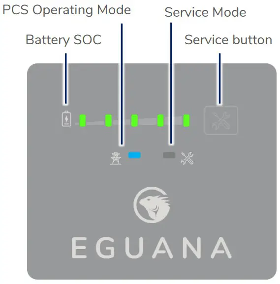
| LED | Mode | Definition |
 |  | State of charge. Each LED represents 20% SOC. Solid = battery idle. Charge = flash right. Discharge = flash left. Low battery |
 | Sleep / Standby mode. Grid timing mode. Grid synchronization mode. Ten second test before grid connect mode. Grid connected mode. | |
 |  | System OK. System out of service. User initiated service mode. |
Service Button
The service button can be used to wake the LED display, and either put the system into or out of service mode, as well as cycle through various operating modes.
IMPORTANT! In the event that the system has gone out of service, please consult your installer for guidance. Depending on the nature of the service fault, your installer may advise you to reset the system on your own, or schedule a service visit.
| Observed state | Action | Service button command |
| Service light on | Exit service mode | Press and hold 5 seconds |
Backup Power Operation
This system will provide backup power to dedicated electrical circuits within the home via a permanently wired electrical sub-panel, referred to as the backup panel. Backup power is limited in rating and duration, both of which are dependent on the nature of the loads connected to the system, and the availability of the solar PV supply. This system is designed to reliably provide power to a refrigerator, lighting, and small appliances.
NOTE: This product is not an uninterrupted power source (UPS). Following a utility outage, a four second power interruption will occur before the backup power source commences. A portable UPS is recommended for devices that require uninterrupted power.
IMPORTANT! Surge rated loads, ie) power tools, portable air conditioners, etc, may cause an overload shutdown. Equipment of this type that is connected to the backup panel should be inspected and tested regularly as per manufacturer suggested schedules. Permanent damage to the battery system and/or your equipment may occur if exposed to chronic overloading cycles. The power output / surge rating will be further limited when the battery is below 10% SOC.
IMPORTANT! Do not attempt to connect a gas generator to the battery system. If generator support is required, consult your installer regarding a separate manual transfer to your backup electrical panel.
Backup power display modes
| Display | Definition |
 | Battery status LEDs indicate the following: • Charge = flash right. Discharge = flash left. • PCS and service lights off. |
 | Low SOC shutdown in backup mode. See section 5.2 to restart the system. |
 | Low SOC shutdown initiated while out of service. See troubleshooting – section 7, “service light on in backup mode”. |
Restarting the battery system after low battery shutdown
The system will shutdown when the battery reaches a critically low level during backup operation. To restart the system:
IMPORTANT! Direct sunlight is required to charge the battery. If the battery system is installed without PV connected to the backup panel, do not attempt the restart. Wait for the utility power to return.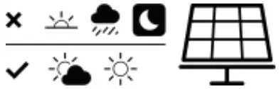
- To increase the battery charge rate and/or prevent further discharge, shut off all home circuits in the electrical switchboard. The battery and solar PV circuits must be ON.

- Press and hold the service button for 5 seconds.

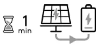
- The battery system will restart. The battery will begin to charge approximately one minute after the PV system is energized. If the battery does not begin to charge within 15 minutes of restart, it will shut down again.

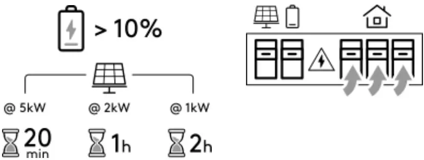
- Where home circuits have been shut OFF in step 1 above, allow the battery to charge to 10%, then turn ON the home circuits. The charge time is dependent on the amount of solar production.


Manually setting the battery minimum SOC reserve
The default minimum SOC reserve is set to optimize the system’s operation in a solar self-consumption mode. In the case of a scheduled grid outage, or a weather event which risks a grid outage, the battery minimum reserve can be manually set to its maximum value to maintain a full battery. Once the event and/or event risk has passed, the setting must be manually returned to the lowest value to return to solar self consumption mode.
Login to the SwitchDin Stormcloud app and follow the steps below to change the minimum SOC reserve.
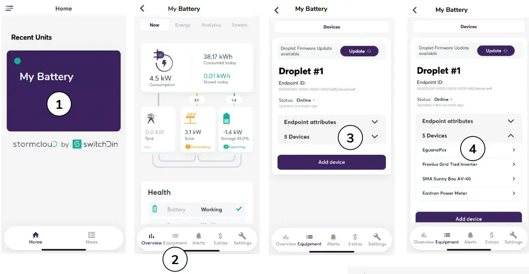
Note: Settings changes require the battery system to be connected to the internet, and battery health = OK as shown in the health block within the Overview menu (see image below – step 2).
- Select ‘My Battery’ (your battery unit’s name).
- Select Equipment in the bottom menu.
- Select Devices (below Endpoint attributes).
- Select EguanaPcs.
- In the Settings window, enter the new SOC limit and select [Update].


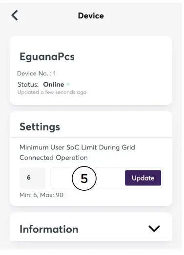
Note: Max = 90
Note: Return the SOC limit to the Min value after the outage event and/or event risk has passed.
Maintenance
The Evolve home energy storage system is a maintenance free product. Regularly scheduled inspection of the airflow path for the active cooling fans on the bottom side of the PCS cabinet is all that is required. This inspection should occur on annually.
If the fan ventilation holes are obstructed with dust / debris, a soft-bristled brush can be used to wipe them clean. For heavy soiling use a soft, dry brush. Do not use any solvents, scouring, or corrosive materials to clean the unit. Never remove or unplug connections or plugs during cleaning.
Troubleshooting
System faults are reported and logged in the monitoring system. All fault logs are also accessible remotely by your installer. Contact your system installer as recommended below if any of the following conditions are present on the front display of the inverter panel.
| PCS indicator status | Definition |
| Service light ON in grid mode | System is prevented from normal operation due to internal fault. Notify service personnel. |
| Service light ON in backup mode | Possible overload condition which prevents the system from operating safely. If the battery SOC is greater than 20% (one or more Green battery status LEDs), reduce the load by shutting off circuits in the backup electrical panel, then press and hold the service button 5 seconds to resume backup power operation. If the battery SOC is less than 20% (SOC Led is yellow), do not attempt to resume backup operation until sunlight is present to provide a solar charge of the battery. |
| All panel lights flashing | System is attempting to communicate with the battery modules. Notify your service provider if this condition persists more than 30 minutes. |
| All panel lights OFF after service button wake command | This indicates loss of both AC And DC sources to the PCS. Notify your service provider. |
| Online monitoring system not accessible | Check the internet connection. If connection is via wi-fi, reboot wireless router, and make sure login user and password have not been changed since time of original installation. Check power to the Evolve energy management system via the orange indicator light on the right side of the panel. Note: the energy management system may lose power after an extended grid outage where there is not enough solar generation to maintain battery system power. Note: monitoring system servers may occasionally be down for service. If first attempts are not successfully, try again the following day before contacting your service provider. |
Installer Checklist
Following the completion of your energy storage system installation, ensure your installer has provided you with the following information for your personal records. Note that we may ask you for this information in the event you need to make a warranty claim:
- Record of purchase, including date of installation, installer name and contact details.
- Copy of the electrical permit.
- Serial numbers for Battery System cabinets (PCS & Battery).
- EMS gateway UID – this is the unique identifier of your EMS gateway that connects to your internet service.
Further to the information provided above, ask your installer to identify the following within your system installation:
- Location of circuit breakers, and if applicable, installed emergency disconnect switches in case an emergency shutdown of the equipment is required.
- Location of the backup electrical panel, including a list and identifier of each circuit within the panel.
- Record of all loads tested at the time of installation.