![]()
 Model Evolve ESS AU
Grid Support Utility Interactive Inverter & Integrated Lithium Battery
Installation & Start-up Guide
For use only with battery model
LG CChem EM048126P3S7
IMPORTANT SAFETY INSTRUCTIONS
SAVE THESE INSTRUCTIONS
This manual contains important instructions for the Evolve™ Home Energy Storage System – including the power control system (PCS) and base model battery cabinet installation and operation. This product is expandable with the addition of up to two more battery cabinets. The Iguana Evolve™ components described by this manual are intended to be used as part of an Energy Storage system and installed as per the local electrical code.![]() CAUTION: Hazardous Voltages! This inverter contains hazardous voltage and energy that may be lethal. It may only be installed by qualified personnel who have read this manual and are familiar with its operation and hazards. The following safety procedures should be followed:
CAUTION: Hazardous Voltages! This inverter contains hazardous voltage and energy that may be lethal. It may only be installed by qualified personnel who have read this manual and are familiar with its operation and hazards. The following safety procedures should be followed:
Only connect the PCS cabinet to a compatible electrical service as defined in the model specifications. The PCS must be connected to a dedicated branch circuit in the main electrical panel.
An external disconnect switch shall be provided in the end installation by others for the AC Grid output circuit.![]() CAUTION! This equipment contains high energy lithium batteries. Qualified and trained personnel should wear protective clothing and equipment when working inside the battery cabinet and/or with battery modules.
CAUTION! This equipment contains high energy lithium batteries. Qualified and trained personnel should wear protective clothing and equipment when working inside the battery cabinet and/or with battery modules.
The PCS is compatible with the LG CChem battery model EM048126P3S7 only.![]() CAUTION! The batteries provided with this system must be charged only by the PCS included as part of the energy storage system. Do not attempt to charge batteries with any other charger device or connect any devices directly to the DC battery bus.
CAUTION! The batteries provided with this system must be charged only by the PCS included as part of the energy storage system. Do not attempt to charge batteries with any other charger device or connect any devices directly to the DC battery bus.
Ensure proper electrical grounding in accordance with code requirements.
Ensure proper airflow path for active cooling.
Never operate system in a manner not described by this manual.
Only qualified personnel should service this product.
Ensure all covers are securely fastened after installation is complete.
This product must be stored indoors in an environmentally conditioned location prior to installation, protected from rain and exposure to any hazardous chemicals.
Do not attempt to operate this product if there is any physical evidence of damage to any of the cabinets or internal components.![]() CAUTION! This equipment is heavy. Mechanical lifts are recommended for safe installation.
CAUTION! This equipment is heavy. Mechanical lifts are recommended for safe installation.
Safety
Throughout this manual, the following symbols will be used to highlight important information and procedures:
| Symbol | Definition |
| WARNING! A dangerous voltage or other condition exists. Use extremecaution when performing these tasks. | |
| CAUTION! This information is critical to the safe installation and or operation of the inverter. Follow these instructions closely. | |
| NOTE: This statement is important. Follow instructions closely. | |
| Meter measurement required. | |
| Torque rating critical to operation. | |
| Login to the remote monitoring system for operating status |
1.1 In case of emergency
In all cases:
If safe to do so, switch off the AC breakers (external to the system) for the system.
- Contact the fire department or other required emergency response team.
- Evacuate the area, and if applicable, follow your emergency evacuation plan if others are in proximity to the installed location.
In case of fire:
- When safe, use a fire extinguisher suitable for use; including A, B, and C dry chemical fire extinguishers or carbon dioxide extinguishers.
In case of flooding:
- Stay out of water if any part of the system or wiring is submerged.
- Do not attempt to operate batteries that have been submerged in water even after they have been dried.
In case of unusual noise, smell or smoke:
- If safe to do so, ventilate the area.
1.2 Battery module safety precautions
This product is integrated with LG CChem EM048126P3S7 series battery modules. Refer to the LG CChem product manual LG CChem P3S series 48V Standalone Battery Module Installation Manual, for complete safety instructions regarding handling of battery modules.
1.3 General safety precautions![]() Important! Installation, service, and operating personnel must read this document in its entirety, and observe all safety and installation procedures as described in this manual. Never operate system in a manner not described by this manual.
Important! Installation, service, and operating personnel must read this document in its entirety, and observe all safety and installation procedures as described in this manual. Never operate system in a manner not described by this manual.
Only qualified personnel should service this product.
Ensure all covers are securely fastened after installation is complete.
Personal Protective Equipment (PPE) in compliance with local work place safety standards must be worn when working inside the cabinet.
Risks of Fire
Do not expose the system to temperatures exceeding 60 degrees Celsius.
Avoid installation in direct sunlight.
Do not store objects on top of the cabinet.
Do not obstruct the intake or exhaust of the forced airflow system.
Do not store combustible objects and corrosive chemicals directly adjacent to the system.
Risks of Shock![]() WARNING! Hazardous Voltages. The Inverter contains hazardous voltage and energy that may be lethal. It may only be installed by qualified personnel who have read this manual and are familiar with its operation and hazards.
WARNING! Hazardous Voltages. The Inverter contains hazardous voltage and energy that may be lethal. It may only be installed by qualified personnel who have read this manual and are familiar with its operation and hazards.
Only connect this product to a compatible electrical service as defined in the model specifications. This product must be connected to a dedicated branch circuit in the main electrical panel.
Ensure proper electrical grounding in accordance with code requirements.![]() CAUTION! Both AC and DC voltage sources are terminated inside this product. Each circuit must be individually disconnected before servicing.
CAUTION! Both AC and DC voltage sources are terminated inside this product. Each circuit must be individually disconnected before servicing.
Risks of Damage![]() This system is compatible with the LG Chem battery model EM048126P3S7 only. Do not attempt to connect any other battery to the system.
This system is compatible with the LG Chem battery model EM048126P3S7 only. Do not attempt to connect any other battery to the system.
Do not connect any other loads, charge controllers, or PV panels directly to the DC battery source.
Do not drop, tip, or puncture the cabinet during transport and installation. Visible damage to the cabinet and/or internal components should be reported to the manufacturer immediately.
Do not store this system for periods longer than six months without a battery maintenance charge.
This may result in permanent damage to the batteries.
1.4 Environmental Protection![]() Do not dispose of the system or any of the components within the cabinet. Batteries, electronics, cables, and metal parts are recyclable. Consult your municipal waste management authority to determine required methods of component recycling.
Do not dispose of the system or any of the components within the cabinet. Batteries, electronics, cables, and metal parts are recyclable. Consult your municipal waste management authority to determine required methods of component recycling.
Introduction
2.1 About this Manual – Target Audience
This manual is intended to be used by qualified service and installation personnel for the purposes of product installation. This product is permanently wired to the home electrical service, and must be installed by a licensed electrician only. This manual contains instructions for the installation and start up sequence of the Eguana Evolve™ home energy storage system; including the PCS and master battery cabinets, the energy meter, and Ethernet connection to a customer supplied internet router.![]() IMPORTANT! This manual makes frequent references to a utility interactive solar PV system as part of an AC coupled solar plus storage installation, which is independently supplied, installed, and operated from the Iguana Evolve ESS. It is the responsibility of the installer to ensure that any utility interactive PV system connected to a backup panel for micro-grid operation is compatible for use with a grid-forming battery inverter.
IMPORTANT! This manual makes frequent references to a utility interactive solar PV system as part of an AC coupled solar plus storage installation, which is independently supplied, installed, and operated from the Iguana Evolve ESS. It is the responsibility of the installer to ensure that any utility interactive PV system connected to a backup panel for micro-grid operation is compatible for use with a grid-forming battery inverter.
The energy management system supplied with this product can monitor the AC power output of an independently installed utility interactive solar PV inverter to operate energy savings algorithms applicable to the local electrical utility; either via CT monitoring, or via compatible communication protocols with a select list of PV inverter models. Consult Eguana Technologies for the most recent list of PV inverters with direct communication to the energy management system.
This product can supply limited backup power, and contains separate grid and load ports to isolate backup loads during a grid outage. When this product is not in service, backup loads are routed directly to the grid panel via the internal PCS bypass relay.
The AC output of an independently installed utility interactive solar PV inverter can be wired to the backup panel to support solar battery charging during backup operation.
The battery capacity of this system can be expanded by adding additional cabinets adjacent to the master battery cabinet. Expansion of battery capacity is not covered within the scope of this document.
2.2 Glossary
| Term | Definition |
| AC | Alternating Current |
| ARC | Auto Recovery Circuit |
| AS/NZS | Standards Australia |
| CEC | Clean Energy Council |
| CPU | Central Processing Unit |
| DC | Direct Current |
| DRED | Demand Response Enabling Device |
| DRM | Demand Response Mode |
| EMS | Energy Management System |
| ESD | Electrostatic Discharge |
| ESS | Energy Storage System |
| GND | Ground |
| LED | Light Emitting Diode |
| NC | Normally Closed |
| NO | Normally Open |
| PCS | Power Control System (Inverter) |
| PE | Protective Earth |
| PV | Photo-Voltaic |
| RF | Radio Frequency |
| SOC | State Of Charge (Battery) |
| SOH | State of Health (Battery) |
2.3 Initial Inspection of Material List
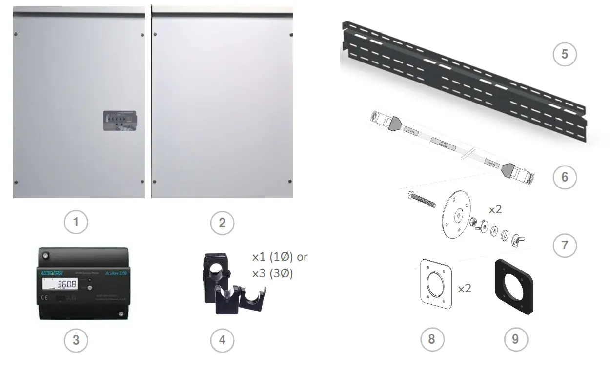
The system components supplied with your Eguana Evolve™ Energy Storage system are shown below. Each component should be inspected visually for any damage that may have been caused by shipment. If damage is present, please contact your local distributor.
2.4 Special Tools & Hardware
In addition to standard tools, the following tools and hardware should be readily available for the installation.
- Torque wrench
- 17mm socket wrench (battery negative main power connection).
- 10mm socket wrench (battery +/- module power connections).
- 3/8” socket wrench (battery positive main power connection).
- RJ-45 crimp tool (EMS to PCS communication cable) and RJ-45 connectors.
- M8 mounting hardware for wall bracket (load bearing).
2.5 Inverter/DSP Firmware Version
The Inverter/DSP firmware version is displayed within the equipment device menu of the Switching Smart Energy application, available both in IOS and Android. Open the application, then proceed to:
Unit >> Equipment (Devices) >> EguanaPCS >> Information: PCS. Field = Inverter/DSP Firmware version.
| Item | Description |
| 1 | ACB05-LP PCS cabinet |
| 2 | ACB05-LB Master battery cabinet |
| 3 | Energy meter |
| 4 | Current transformer(s) |
| 5 | Wall bracket |
| 6 | BMS – PCS high level communication cable |
| 7 | PCS and battery cabinet levelling brackets |
| 8 | Cabinet coupler plates |
| 9 | Cabinet coupler gasket |
| Cabinet coupler hardware (not shown) 4 ea M4 bolts 4 ea M4 star washers 4 ea M4 lock nuts |
2.5 Inverter/DSP Firmware Version
The Inverter/DSP firmware version is displayed within the equipment device menu of the Switch Din Smart Energy application, available both in IOS and Android. Open the application, then proceed to:
Unit >> Equipment (Devices) >> EguanaPCS >> Information: PCS. Field = Inverter/DSP Firmware version.
Installation Site Preparation
Before installing the Evolve home energy storage components, read all instructions and warnings in this manual.![]() CAUTION! All electrical installation work should be performed in accordance with local building and electrical codes.
CAUTION! All electrical installation work should be performed in accordance with local building and electrical codes.![]() WARNING! Isolate the PCS from all energy sources prior to electrical installation by means of disconnects, breakers or connectors. Failure to properly isolate either AC or DC sources may result in serious injury or death. This system will generate an AC voltage at the off-grid terminals when DC source is applied.
WARNING! Isolate the PCS from all energy sources prior to electrical installation by means of disconnects, breakers or connectors. Failure to properly isolate either AC or DC sources may result in serious injury or death. This system will generate an AC voltage at the off-grid terminals when DC source is applied.![]() CAUTION! The PCS cabinet weighs up to 65 kg, and the battery cabinet weighs up to 102 kg.
CAUTION! The PCS cabinet weighs up to 65 kg, and the battery cabinet weighs up to 102 kg.
Handle with care. The wall must be load-bearing rated according to the local building code.
Mechanical lifts are recommended to position cabinets on the wall bracket.
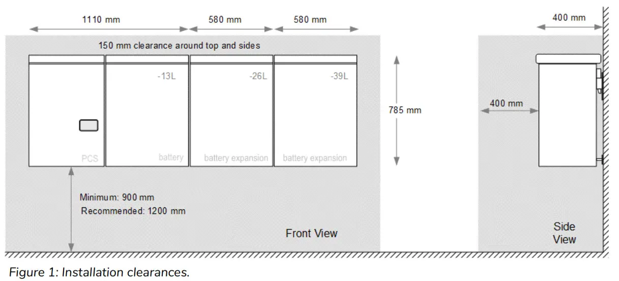
3.1 Locating the system
- The installation location must comply with the environmental rating of the product. Refer to the environmental ratings in section 16.2 of this manual.
 CAUTION! Do not install in direct sunlight. Battery performance is dependent upon operating ambient temperature. Radiant heat absorbed in direct sunlight will greatly reduce the performance of the battery, and will prematurely cause degradation of the display indicator panel on the PCS cabinet. The battery modules are rated for full power operation between -10C to +45C.
 - The forced air cooling of the PCS cabinet is from bottom to top. Refer to figure 1 for recommended layout plan.
- All inter-cabinet cabling is limited in length. Separating cabinets is not permitted.
- Wall mounting hardware not included. The load-bearing wall bracket is provisioned for M8 hardware. Levelling brackets are provisioned for M5 hardware.
3.2 Installation Area Required to Wall Mount PCS and Battery:
The physical installation of the cabinets requires the layout planning and installation of the system components in the available installation space. The recommended installation height is driven by the viewing angle of the display panel on the PCS cabinet.
3.3 Installation plan – power and communication circuits
The following example outlines the conduit plan for power and communication circuits for the battery system. In this example, the PV inverter is coupled to a backup power sub-panel. The sub-panel may also be an isolated power bus within the main electrical panel.
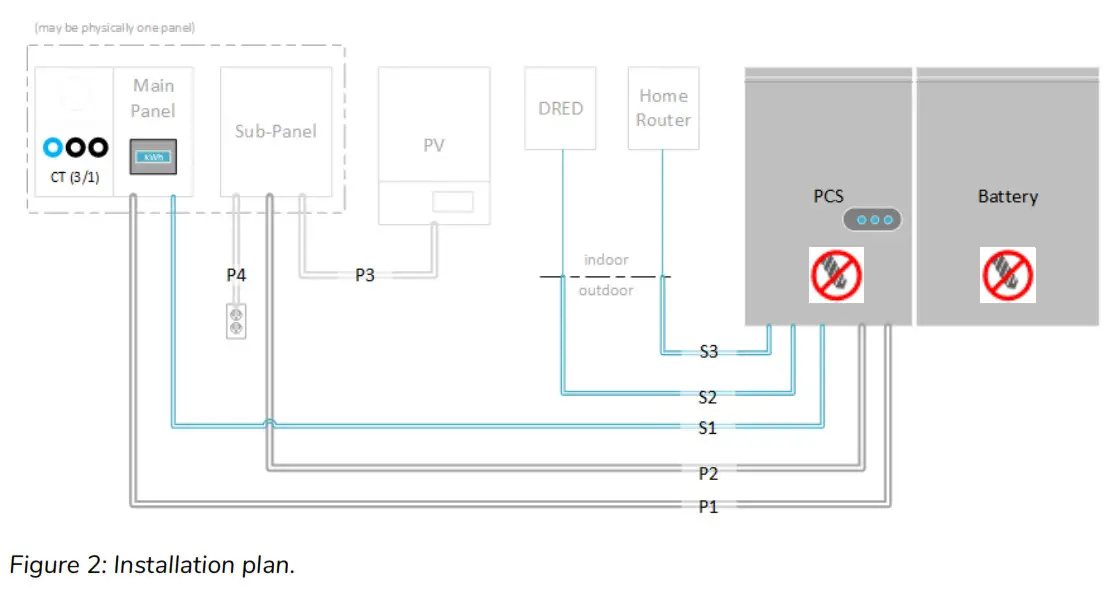
| Signal | Definition | Rating |
| P1 | Grid power* | 10 kVA max (5 kVA battery + 5 kVA PV), 230 Vac, 1Ø |
| P2 | Backup power | 5 kVA max, 230 Vac, 1Ø only |
| P3 | PV power (AC), coupled to backup | 5 kVA max, AC, 1Ø only |
| P4 | Home load circuit(s), backup power | 2 ccts max, 16 A / 230 Vac, 1Ø only |
| S1 | Energy meter (RS-485) | CAT-5, STP |
| S2 | DRED device, Ethernet | CAT-5, UTP |
| S3 | Home router, Ethernet | CAT-5, UTP |
* The battery system is rated 5 kVA maximum. Solar self consumption prevents battery power export, however, the grid power circuit must electrically accommodate the total of both battery and PV generation when PV is connected to the backup circuit.
3.4 SLD – AC Coupled PV System with Back-up Power Operation
The single line diagram shown below is a representation of a typical installation configured for utility interactive and back-up power operation, with AC coupled PV connected to a critical load panel. This drawing is a guideline only, and is not a substitute for a code compliant installation. All components required for a code compliant installation are the responsibility of the licensed installer, including any additional circuit protection requirements not shown here.
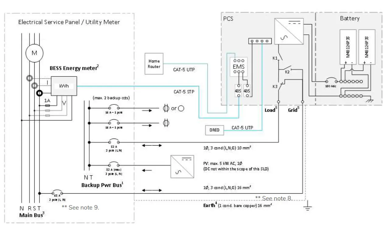
Figure 3: Single Line Diagram: Typical AC coupled PV system.
NOTES
- The backup power bus must be electrically isolated from the main electrical bus. Do not tap the neutral wires of the main and backup buses. A separate line, neutral, and ground must be run to each of the load and grid ports of the battery system. Refer to the installation manual for wiring details.
- Energy meter supports 1Ø and 3Ø configuration.
- 3Ø service shown. For 1Ø service, do not populate R,S ph components.
- The battery system must be earth bonded to the building ground to meet lightning protection requirements.
- The battery system load and grid ports are independently controlled circuits. Should the electrical code require additional “line-of-sight” disconnects, a separate disconnect must be used for each of the grid and load ports. The disconnects and/or circuit breakers must operate independently of each other, and not be ganged.
- The PCS provides galvanic separation of AC and DC sources. Overcurrent protection devices, RCD Type A, are sufficient for protection of both AC Grid and AC load ports.
- Total AC nameplate of PV not to exceed 5 kW. String inverter shown for simplicity. Multiple AC strings of microinverters permitted. Any additional PV installed on the grid side of the battery system operates independently from the battery system, and is only limited by the interconnection requirements of the utility service provider.
- The maximum conductor size permitted for the PCS grid port is 16 mm 2 , and maximum breaker rating of 63 Amp to protect the internal circuits of the PCS. The ESS breaker rating and conductor size can be reduced, however, these parameters are subject to the total possible continuous output current of combined PV and ESS generation at the ESS grid breaker in the main electrical panel. Variables that determine conductor sizing include; PV continuous output current rating connected to the ESS load terminal, total self-supply current to the main electrical panel (load connected PV plus ESS output), and length of run from the ESS grid port to the main electrical panel (voltage drop). Conductor sizing is the responsibility of the installer as per the actual installation, compliant to local / national electrical codes. Refer to the technical data in section 16.1 for Maximum AC fault current and duration (short circuit).
- The PCS short circuit withstand capacity is rated at 10 kA (1 second). Circuit protection must not exceed this rating. *DRED: Australia only.
PCS and Battery Cabinet Wall-Mounting Instructions
- Mount the wall bracket to the wall. Use the available slot pattern to mount to a load-bearing structure rated for the weight of the final system. The slots accommodate a M8 bolt diameter. IMPORTANT! Wall-stud mounting: A minimum of three wall studs spanned within the width of the mounting bracket are required. A minimum of two mounting bolts are required per stud (top/bottom).
- Remove the master battery cabinet from the packaging, and stand the cabinet upright. (not shown). Remove the front cover.
- Assemble the lower leveling bracket. (Fully assembled drawing shown – the last washer and wing nut are mounted from inside the cabinet).
- Mount the leveling bracket to the cabinet. CAUTION! Battery cabinet is heavy. Mechanical lift recommended.
- Lift the battery cabinet onto the wall mount bracket, aligning the wall hooks at the rear of the cabinet with the slots on the load-bearing face of the bracket.
- Slide the battery cabinet towards the right end of the bracket to allow for clearance for the PCS cabinet.
- From the rear side of the cabinet, spin the lower levelling bracket (in/out) until the cabinet is vertically plumb (level) to the wall.
- Remove the PCS cabinet from its packaging and stand upright. (not shown). Remove the front cover.
- Assemble and mount the leveling bracket as shown in steps 3 and 4 above.
 Figure 4: Wall mount bracket and battery cabinet installation. CAUTION! The PCS cabinet is heavy. Mechanical lift recommended.
 - Lift the PCS cabinet onto the wall mounting bracket.
- Slide the PCS cabinet to the left such that it aligns with the alignment tab on the mounting bracket.
- From the rear side of the cabinet, spin the lower levelling bracket (in/out) until the cabinet is vertically plumb (level) to the wall (as shown in step 7).
 WARNING! The mounting bolts of the flange assembly are required to be fully secured to provide the chassis grounding for the battery cabinet. Torque nuts as specified in the specification tables provided in this manual.
 - Insert the PCS cabinet coupling gasket between the two cabinets (lower-front). Slide the battery cabinet towards the left until mating to the gasket.
- Place the coupling plate inside the PCS cabinet and insert the four mounting bolts and washers through to the battery cabinet side.
- Place star washers on the bolts on the battery side of the cabinet.
- Mount the battery cabinet side coupling plate, and fasten with the lock nuts.
 Continuity test: Check the continuity between the cabinets using an Ohm meter. The test reading must be zero Ohms at a bare metal point inside each of the PCS and battery cabinets.
- Optional: (This is not a load bearing anchor – anchored conduit runs to the PCS are satisfactory). Install screws in leveling plates for PCS and battery cabinets by inserting a screwdriver through the hole on the backside of the cabinets.
- Plug hole on back of cabinet using by inserting the hole plug from the front side.
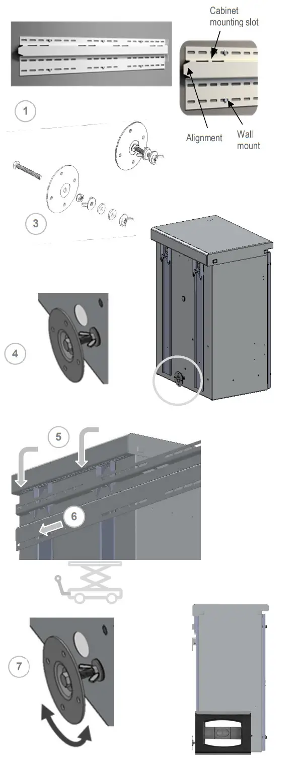 Figure 4: Wall mount bracket and battery cabinet installation.
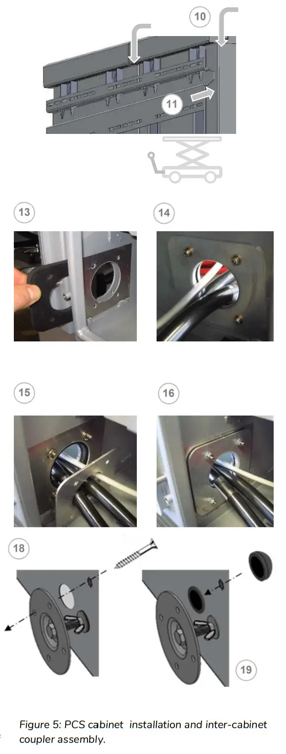
PCS / Battery Inter-Cabinet Wiring
The following instructions cover the interconnection wiring of the PCS and master battery cabinet. No cable preparation is required with battery modules pre-installed in the cabinet. Refer to appendix A for a complete inter-cabinet wiring diagram.![]() Note: Overcurrent protection of the DC source is provided internally as part of the integrated battery system. No external DC disconnect is required.
Note: Overcurrent protection of the DC source is provided internally as part of the integrated battery system. No external DC disconnect is required.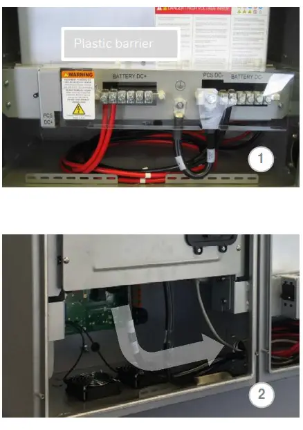 5.1 Battery power cable connections
![]() CAUTION! A torque wrench is required tonsure the power cables are terminated toothier specifications. Over-torque can damage the DC breaker and/or strip the threads on thecopper bus bar posts. Under-torque can result in an arc fault hazard, and risk of fire. Damage as a result of improper termination is not covered by the manufacturer warranty.
CAUTION! A torque wrench is required tonsure the power cables are terminated toothier specifications. Over-torque can damage the DC breaker and/or strip the threads on thecopper bus bar posts. Under-torque can result in an arc fault hazard, and risk of fire. Damage as a result of improper termination is not covered by the manufacturer warranty.
- Remove the plastic safety barrier on the power panel assembly inside the master battery cabinet by removing the three white plastic lug nuts on the top of the safety barrier.
- Route the battery cables from the PCS cabinet to the battery cabinet.
- Loosen the PCS DC- terminal bolt using a 17mm socket wrench. Remove the ground cable.
 Place the DC- cable and ground cable ring terminals back-to-back, and mount them to the PCS DC- bus bar. Tighten the bolt using the 17mm socket. Torque to 6.8 Nm.
- Connect the Battery positive (+) cable to the PCS Batt+ bus bar terminal on the rear of the battery disconnect switch using a 3/8” socket wrench. Torque to 4.0 Nm.

 Place the DC- cable and ground cable ring terminals back-to-back, and mount them to the PCS DC- bus bar. Tighten the bolt using the 17mm socket. Torque to 6.8 Nm.
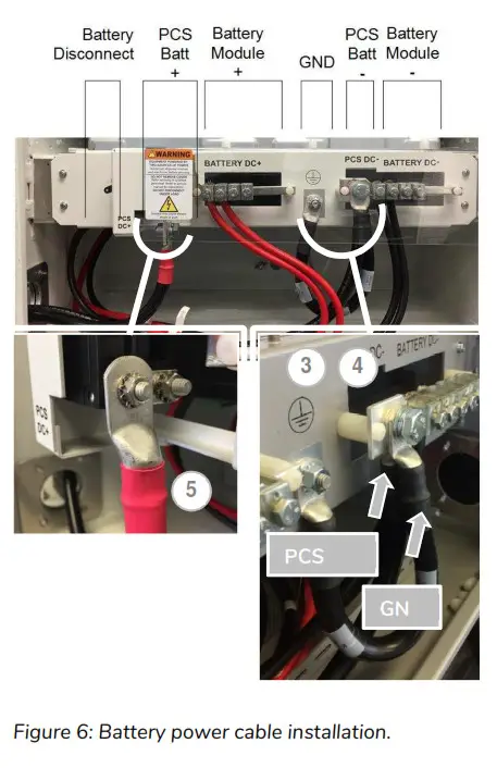
5.2 Battery BMS to PCS communication connection
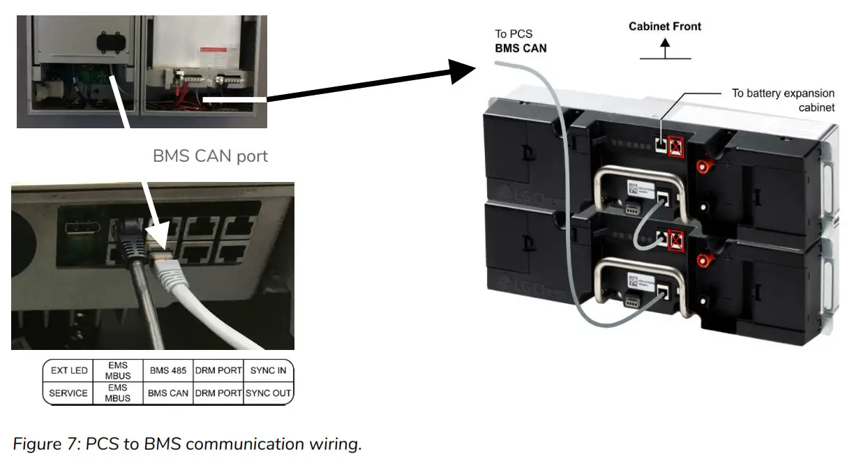
The communication cable can be routed with DC power cables. Take care that the communication cable is routed through the inter-cabinet coupler so that there is no stress or tension on the terminations. This cable is terminated with RJ-50, 10-pin connectors.
- PCS cabinet: Terminate the cable (p/n 801003338) at the BMS CAN port, as shown in figure 7, above-left.
- Battery cabinet: Terminate the cable at the rear battery module BMS port as shown above-right.
System Electrical Wiring
![]() Note: This product is capable of providing utility interactive and islanded back up power, and can be AC coupled to a utility interactive photovoltaic inverter. Wiring methods must be in accordance with local electrical codes. The installer is responsible for ensuring that over-current protection is installed and sized appropriately for the AC grid and off-grid output circuits, in accordance with the AS/NSZ electrical code.
Note: This product is capable of providing utility interactive and islanded back up power, and can be AC coupled to a utility interactive photovoltaic inverter. Wiring methods must be in accordance with local electrical codes. The installer is responsible for ensuring that over-current protection is installed and sized appropriately for the AC grid and off-grid output circuits, in accordance with the AS/NSZ electrical code.
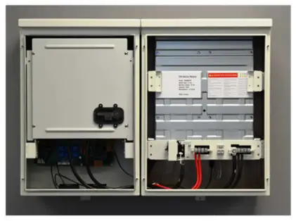
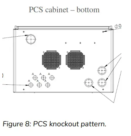
All field wiring connections to the battery system are at the PCS cabinet only. The diagram (left) indicates the knockout locations for conduit entry into the PCS; categorized as AC power and signal level circuits.
IMPORTANT! Drilling holes anywhere in the battery or PCS cabinet renders the warranty null and void. Use the knockouts provided at the bottom face of the PCS cabinet only! Do not drill holes anywhere in the battery system. Use conduit fitting reducers, if applicable.
6.1 AC power connections
This battery system contains two independent AC power connection ports; one port dedicated for an electrical utility connection, marked “AC Grid”, the other port educated for backup operation, marked “AC load”. This product’s primary application is intended for utility interconnection, and must be connected to a utility electrical service supplying single phase 230 Vac / 50 Hz. The backup operation of this product is a secondary application, and is intended to supply emergency backup operation only. Under circumstances should this product be used solely as an off-grid storage system, nor should it be expected to perform whole home emergency backup power.![]() Note: The PCS provides galvanic separation between AC and DC Sources. RCD protective devices of Type A are sufficient for use as circuit over-current protection for both AC Grid and AC Load ports.
Note: The PCS provides galvanic separation between AC and DC Sources. RCD protective devices of Type A are sufficient for use as circuit over-current protection for both AC Grid and AC Load ports.![]() CAUTION! To reduce the risk of fire, connect only to a dedicated circuit provided with appropriate branch circuit overcurrent protection in accordance with local electrical codes.
CAUTION! To reduce the risk of fire, connect only to a dedicated circuit provided with appropriate branch circuit overcurrent protection in accordance with local electrical codes.![]() WARNING! Improper connection of the wiring panel may result in equipment damage and cause personal injury. Disconnect all AC and DC Sources prior to installation.
WARNING! Improper connection of the wiring panel may result in equipment damage and cause personal injury. Disconnect all AC and DC Sources prior to installation.![]() CAUTION! The AC grid and load ports are independent circuits, controlled internally by an automatic bypass and transfer switch. Each port must be connected to electrically isolated panels. Tapping line or neutral wires from the main electrical panel to the backup panel will result in permanent damage to the product.
CAUTION! The AC grid and load ports are independent circuits, controlled internally by an automatic bypass and transfer switch. Each port must be connected to electrically isolated panels. Tapping line or neutral wires from the main electrical panel to the backup panel will result in permanent damage to the product.
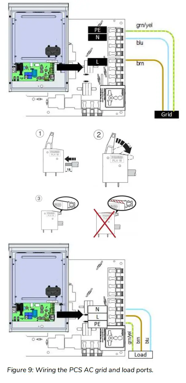
- AC Grid Port: Open the spring clamp terminals on the AC circuit board at the port marked “AC Grid”.
- Terminate the AC grid connection wires as follows: “Lagid” = Line, “Negri” = Neutral, and “PE” = Ground
- Close the spring clamp terminals, ensuring levers are fully engaged.
- AC Load Port: Open the spring clamp terminals on the AC circuit board at the port marked “AC Load”.
- Terminate the wires at “L_AC load” (Line), “N_AC load” (neutral), and “PE_AC load” (protective earth).
- Close the spring clamp terminals, ensuring levers are fully engaged.
6.2 Chassis Grounding
In this section, “Chassis Ground” is referred to as “ground” or “grounding” unless otherwise mentioned.
The PCS cabinet is shipped with ungrounded DC power terminals within the inverter. When terminated to the batteries, the DC bus is configured for DC negative to ground.
AC Grid Earthing System: The AC power grounding is achieved through the PE terminals of the AC grid connectors on the AC Filter Board, as shown in section 6.1. The PCS is configured by default for a TN earthing system.
Note: The field ground wire rating applies to the AC circuit only. The DC source loop is internal to the battery cabinet, and is rated accordingly.
Lightning Grounding: The inverter has built-in lightning protection. In order for the lightning protection to be effective, the grounding for lightning currents must be provided via low impedance path from the PCS PE terminal to the building Ground/Earthing point.
Energy meter installation
The energy management system’s solar self-consumption algorithm requires the connection of an energy meter at the customer’s main electrical panel. The meter must be installed and configured according to the electrical service; either single phase or three phase. The information covered in this guide is generic to the approved list of integrated energy meters that are supported by the home storage system at the time of your purchase. Refer to the energy meter manufacturer’s installation manual supplied with your system for full installation details and safety information.![]() Note: Refer to Appendix B for wiring diagrams specific to the manufacturer and model of the energy meter supplied with your system.
Note: Refer to Appendix B for wiring diagrams specific to the manufacturer and model of the energy meter supplied with your system.
7.1 Energy meter location
The meter supplied must be installed inside or near the home’s electrical service panel. CT’s supplied with the meter are provided with standard 2.4 meter length wires. The meter must be located such that the CT’s can be terminated without extensions. If there is no room inside the electrical panel, the meter should be installed adjacent to the panel in an enclosure rated for the environment in which it is installed. Energy meters supplied with the home storage system are DIN rail mounted. Use existing DIN rail space within the electrical panel, or add DIN rail as required.
7.2 Electrical connections – voltage measurement / power supply
The energy meter provided is line powered from the electrical service. An in-line fuse, rated 1 Amp / 250 VAC, is required on the voltage line input to the meter. For three phase service, fuses are required on the V1, V2, and V3 input terminals. The voltage inputs can be connected anywhere on the customer side of the main service disconnect breaker. For three phase systems, phase rotation is automatically configured by the meter.
The energy meter provided is line powered from the electrical service. An in-line fuse, rated 1 Amp / 250 VAC, is required on the voltage line input to the meter. For three phase service, fuses are required on the V1, V2, and V3 input terminals. The voltage inputs can be connected anywhere on the customer side of the main service disconnect breaker. For three phase systems, phase rotation is automatically configured by the meter.
7.3 CT (current transformer) connections ![]() Note: Observe the current flow direction of the CT. The direction of flow must be away from the utility meter. For three phase systems, phase rotation is automatically configured by the meter.
Note: Observe the current flow direction of the CT. The direction of flow must be away from the utility meter. For three phase systems, phase rotation is automatically configured by the meter.![]() CAUTION! Handle CTs with care. Always terminate the CTs at the meter inputs prior to clamping the core onto a hot wire.
CAUTION! Handle CTs with care. Always terminate the CTs at the meter inputs prior to clamping the core onto a hot wire.
This system is supplied with split-core CTs for installation without interruption to the electrical service. The CTs must be mounted on the primary electrical bus, between the main service breaker disconnect and the utility’s energy meter. This is important to ensure all loads and generation are captured for optimum performance of the solar self consumption control algorithms.
7.4 RS-485 communication connection
The battery system communicates with the meter using the Modbus protocol over an RS-485 network. Shielded twisted pair cable is required.
The battery system communicates with the meter using the Modbus protocol over an RS-485 network. Shielded twisted pair cable is required.![]() Note: Shield wire connected to earthing terminal at a single point only. Terminate the cable as shown (TIA/EIA 568B standard):
Note: Shield wire connected to earthing terminal at a single point only. Terminate the cable as shown (TIA/EIA 568B standard):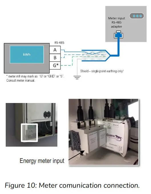
| Signal | RJ-45 Pin | Wire color |
| GND | 3 | green/white |
| A | 4 | blue |
| B | 5 | blue/white |
Droplet Ethernet connection to Home Router
A Wi-Fi connection to the battery system is permitted for remote monitoring of the system, however, a permanent connection is strongly recommended for reliable communication access to the system. The Ethernet wiring from the battery system must be connected to a customer supplied router. A permanent Ethernet connection to the battery system requires external wiring. Compliance with local electrical code is the responsibility of the installer. Conduit and fittings connected to this equipment must ensure compliance with the IEC environmental rating as per the equipment ratings.
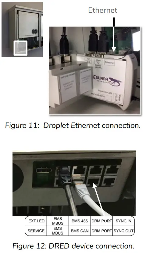
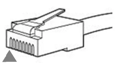
8.1 Ethernet cable connection
The Ethernet connection is a standard RJ-45 straight through configuration. Standard EIA/TIA termination practices are recommended.
- Remove the knockout dedicated for the Ethernet connection.
- Secure the communication cable strain relief (conduit fitting, if applicable).
- Terminate the routed cable as a straight-through Ethernet connection.
- Test the cable prior to connection.
- Connect the cable to the Droplet’s Ethernet port as shown.
DRED Device Connection: (Australia)
- Connect the DRED device to the DRM Port at as shown
Start-up Sequence
![]() CAUTION! Powering the Evolve home energy storage system requires a specific start-up procedure. Please follow the steps below.
CAUTION! Powering the Evolve home energy storage system requires a specific start-up procedure. Please follow the steps below.![]() CAUTION! If the battery disconnect has been placed in the OFF position at any time during operation, wait one minute before returning to the ON position. Rapid cycling (less than one minute) of the battery disconnect can cause damage to the pre-charge circuit.
CAUTION! If the battery disconnect has been placed in the OFF position at any time during operation, wait one minute before returning to the ON position. Rapid cycling (less than one minute) of the battery disconnect can cause damage to the pre-charge circuit.![]() CAUTION! During the first start-up sequence after installation, the battery modules may require a battery maintenance cycle to balance the SOC. This maintenance cycle requires a grid connection so that the PCS can be commanded to charge the batteries. The PCS battery SOC alarm light will flash yellow if maintenance and/or other battery faults are present. This procedure may take from a few minutes to a few hours, depending on the difference in battery module SOC. Please refer to the PCS Service Manual for more information.
CAUTION! During the first start-up sequence after installation, the battery modules may require a battery maintenance cycle to balance the SOC. This maintenance cycle requires a grid connection so that the PCS can be commanded to charge the batteries. The PCS battery SOC alarm light will flash yellow if maintenance and/or other battery faults are present. This procedure may take from a few minutes to a few hours, depending on the difference in battery module SOC. Please refer to the PCS Service Manual for more information.
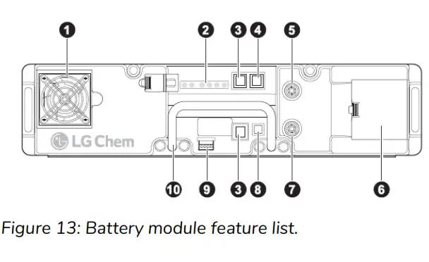
- Fan
- Status indicators
- RJ48 port for intra-rack communication cable
- RJ48 port for higher-level communication cable
- Positive connector (+)
- Power terminal compartment
- Negative connector (—)
- On/Off button
- Dry contact
- Handle
- Remove the front cover from the battery cabinet adjacent to the PCS cabinet.
- Press the [Power] button (see above, label #8) on the master battery module. The master battery module has communication wired from the battery BMS port (label #4) to the PCS [BMS in] port. WARNING! When the batteries are turned ON, the battery voltage will be present at the power panel assembly bus bar where the battery modules are terminated.
This step may take up to one minute.
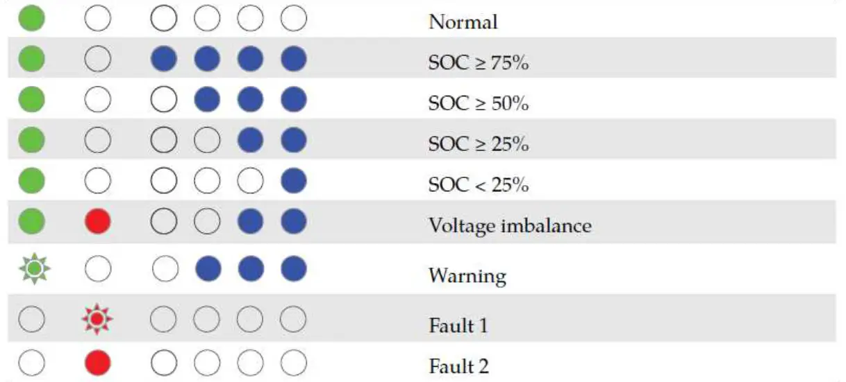
Verify that the indicators are as shown in “Normal Operation” as shown below. Battery Power Button Operation WARNING! The master battery turns on all other battery modules in the battery rack via the communication network. Do not use power buttons to turn each module on individually. This may cause damage to one or more batteries on the DC bus.
Turn Batteries ON: Press and Release the power button on the module designated as the Master module (PCS connected com cable).
Turn Batteries OFF: Press and hold 5 seconds the power button of any module designated as a Slave Module. If all modules do not shut off, repeat individually for each module.
Green indicator: The left indicator indicates normal operation. Blue indicators (SOC): In normal operation, the four indicators on the right show the module’s state of charge (SOC). Each indicator represents 25% of a full charge. If the SOC value is 50%, the three rightmost indicators are on solid BLUE. The blue indicators of the slave modules look as below.
 Whereas, the leftmost blue indicator on the master module flashes.
 Also, verify that the module with the left-most flashing blue SOC indicator corresponds to the module which has communication wired from the BMS to the PCS [BMS in] port. CAUTION! If any battery module other than the master has a flashing SOC light at startup, shut down all battery modules by holding the [Power] button for 5 seconds. In this state, it may be necessary to shut down battery modules individually. After all modules are OFF, repeat step 2.
 - Turn ON the Battery disconnect switch inside the battery cabinet. IMPORTANT! The DC breaker is not intended for use as an external service disconnect. It is intended only for authorized service personnel as part of the startup sequence and/or equipment service only. Overload protection is provided by the fuses within the battery modules.
The PCS module will initialize, indicated by a brief flash of all LEDs on the display panel, followed by a status of the battery and PCS. Refer to table in section 12.2 for definitions of the indicator status of the PCS. - Turn ON the AC breaker at the main electrical panel to the PCS.
 Battery Power Button Operation
 Blue indicators (SOC): In normal operation, the four indicators on the right show the module’s state of charge (SOC). Each indicator represents 25% of a full charge. If the SOC value is 50%, the three rightmost indicators are on solid BLUE. The blue indicators of the slave modules look as below.
 Whereas, the leftmost blue indicator on the master module flashes.
 Also, verify that the module with the left-most flashing blue SOC indicator corresponds to the module which has communication wired from the BMS to the PCS [BMS in] port.
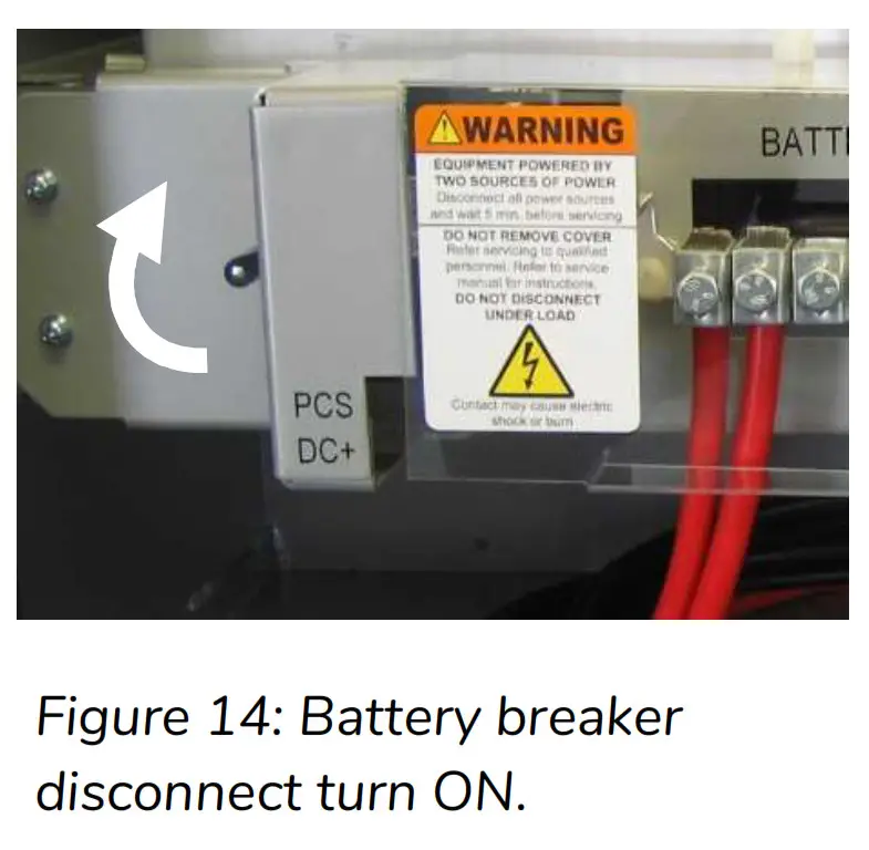
Operation
 The Evolve home energy storage system is fully automated. The EMS will be programmed to connect the system to the grid after AC and DC sources are applied. Refer to the user interface manual for system monitoring and operation status. The operating states can also be viewed on the PCS display panel.
PCS Display Panel
12.1 LED Display Indicators
The PCS cabinet is equipped with a display panel that provides indication of the following:
- Battery Operating State
- PCS Operating State
- (out of) Service Indicator
Refer to section 12.2 for a complete definition of indicator states.
To conserve energy, the LEDs will turn off after 5 minutes from being activated. They can be re-activated by pressing the service button.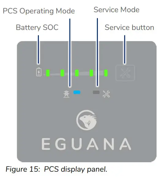
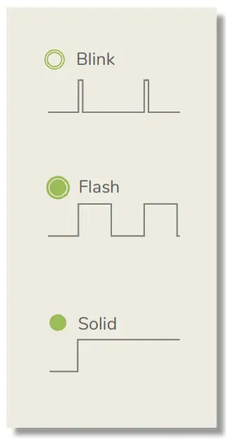
12.2 PCS display panel indicator summary.
The LEDs on the PCS identify operating states by both display mode and color.
| LED | Mode | Definition |
| State of charge. Each LED represents 20% SOC. Solid = battery idle. Charge = flash right. Discharge = flash left. Low battery. | ||
| Sleep / Standby mode. Grid timing mode. Grid synchronization mode. Ten second test before grid connect mode. Grid connected mode. | ||
| System OK. System out of service. User initiated service mode. |
12.3 Service Button
The service button can be used to wake the LED display, and either place the system into or out of service mode, as well as cycle through various operating modes. If the system has gone into service mode, the user can attempt to bring the system back into normal operation using the service button.![]() Note: It is recommended to login to the EMS via web browser and retrieve the service code from the system prior to attempting to clear the service mode.
Note: It is recommended to login to the EMS via web browser and retrieve the service code from the system prior to attempting to clear the service mode.
| Observed state | Action | Service button command |
| All panel lights off | Wake panel display | Press and release |
| Service light on | Exit service mode | Press and hold 5 seconds |
Refer to section 14 – Troubleshooting if the service button does not perform the action requested.
12.4 Backup Power Operation
This system will provide backup power to dedicated electrical circuits within the home via a permanently wired electrical sub-panel, referred to as the backup panel. Backup power is limited in rating and duration, both of which are dependent on the nature of the loads connected to the system, and the availability of the solar PV supply. This system is designed to reliably provide power to a refrigerator, home lighting, home electronics, and small appliances.![]() NOTE: This product is not an uninterrupted power source (UPS). Following a utility outage, a four second power interruption will occur before the backup power source commences. As a result of this interruption, a desktop or portable UPS is recommended if continuous operation is desired for any electronic devices.
NOTE: This product is not an uninterrupted power source (UPS). Following a utility outage, a four second power interruption will occur before the backup power source commences. As a result of this interruption, a desktop or portable UPS is recommended if continuous operation is desired for any electronic devices.![]() IMPORTANT! Surge rated loads, i.e. power tools, portable air conditioners, may cause an overload shutdown. Equipment of this type that is connected to the backup panel should be inspected and tested regularly as per manufacturer suggested schedules. Permanent damage to the battery system and/or your equipment may occur if exposed to chronic overloading cycles.
IMPORTANT! Surge rated loads, i.e. power tools, portable air conditioners, may cause an overload shutdown. Equipment of this type that is connected to the backup panel should be inspected and tested regularly as per manufacturer suggested schedules. Permanent damage to the battery system and/or your equipment may occur if exposed to chronic overloading cycles.![]() IMPORTANT! Portable extension cords connected to a backup circuit should be limited to 10 meters.
IMPORTANT! Portable extension cords connected to a backup circuit should be limited to 10 meters.![]() IMPORTANT! This product does not support automatic gas generator integration. Do not attempt to connect a gas generator to the battery system. If generator support is required, consult your installer regarding a separate manual transfer to your backup electrical panel.
IMPORTANT! This product does not support automatic gas generator integration. Do not attempt to connect a gas generator to the battery system. If generator support is required, consult your installer regarding a separate manual transfer to your backup electrical panel.![]() NOTE: The power output / surge rating will be further limited when the battery is below 10% SOC.
NOTE: The power output / surge rating will be further limited when the battery is below 10% SOC.
12.4.1 Backup Power Display Modes
| Display | Definition |
| Battery status LEDs indicate the following: • Charge = flash right. Discharge = flash left. • PCS and service lights off. | |
| Low SOC shutdown in backup mode. See section 9.5 to restart the system. | |
| Low SOC shutdown initiated while out of service. See troubleshooting – section 7, “service light on in backup mode”. |
12.5 Off-grid mode: Restarting the battery system after low battery shutdown
The system will shut down when the battery reaches a critically low-level during backup operation.
To restart the system:![]() IMPORTANT! If the battery system is installed without a PV system connected to the backup panel, do not attempt to restart it. For systems with backup panel connected PV, ensure there is direct sunlight for the solar PV system to charge the battery before restarting the system. Wait for the utility power to return.
IMPORTANT! If the battery system is installed without a PV system connected to the backup panel, do not attempt to restart it. For systems with backup panel connected PV, ensure there is direct sunlight for the solar PV system to charge the battery before restarting the system. Wait for the utility power to return.
- Press and hold the service button on the front of the display panel for 5 seconds.

The backup power will restart, allowing the PV system to energize and charge* the battery. The system will continue to operate if the battery charges to its minimal normal operating range. If the battery does not charge within 15 minutes of restart, the system will shut down to preserve the battery.
*Australia – the PV system begins to generate one minute after being energized.![]() Note: De-energize any home loads by shutting off the circuit breakers in the eletrical switchboard to increase the charge rate of the battery from the solar PV array. Do not shut off the PV or battery circuits. It is strongly recommended to charge the battery to a minimum of 10% state-of-charge before energizing any home loads.
Note: De-energize any home loads by shutting off the circuit breakers in the eletrical switchboard to increase the charge rate of the battery from the solar PV array. Do not shut off the PV or battery circuits. It is strongly recommended to charge the battery to a minimum of 10% state-of-charge before energizing any home loads.
The charge rate of the battery is dependent upon the available solar PV output. As a general rule, the battery will charge to 10% SOC at the following rates:
| PV output, kW | 10% Charge duration, minutes |
| 1 | 120 |
| 2 | 60 |
| 5 | 20 |
Maintenance
The Evolve home energy storage system is a maintenance free product. Regularly scheduled inspection of the airflow path for the active cooling fans on the bottom side of the PCS cabinet is all that is required. This inspection should occur on an annual basis, or coincide with PV inspection.
If the fan ventilation holes are obstructed with dust / debris, a soft-bristled brush can be used to wipe them clean. For heavy soiling use a soft, dry brush. Do not use any solvents, scouring, or corrosive materials to clean the unit. Never remove or unplug connections or plugs during cleaning.
Troubleshooting
System faults are reported and logged in the monitoring system. All fault logs are also accessible remotely by your installer.![]() IMPORTANT! Contact your system installer immediately if any of the following conditions are present on the front display of the inverter panel.
IMPORTANT! Contact your system installer immediately if any of the following conditions are present on the front display of the inverter panel.
| PCS indicator status | Definition |
| Service light ON | System is prevented from normal operation due to internal fault. |
| All panel lights flashing | System is attempting battery recovery. Notify service personnel if this condition persists more than 30 minutes. |
| All panel lights OFF after press/release of service button | This indicates loss of both AC And DC sources to the PCS. |
| Sleep/standby mode engaged | This is a normal operating mode initiated by the EMS when the battery SOC reaches the maximum or minimum SOC. Loss of EMS communication will also engage the PCS into sleep/standby mode. If on initial power up of the system, the PCS does not exit sleep/ standby mode, and one to four battery SOC lights are ON, inspect the EMS to PCS communication cable , and verify that the EMS is powered. |
Serviceable Parts – Battery module removal/replacement
The battery modules within the battery cabinet are removable and/or replaceable. To replace or remove the battery modules:
- Follow section 5 in this manual to disconnect the inter-cabinet cabling.
- Refer to the 68006 Battery Module Field Assembly Guide for instructions on removing the battery modules. Assembly and disassembly are the reverse order.
Technical Data
16.1 PCS cabinet data
| Electrical & performance data, AC | |
| Grid voltage | 230 / 240 Vac |
| Grid frequency | 50 Hz |
| Maximum continuous operating current | 21.7 Amps |
| Maximum continuous operating power | 5000 VA |
| Power factor, nominal (range) | > 0.99 (0.8 lead to 0.8 lag) |
| Efficiency, % peak (average) | 96 (94.5) |
| Maximum AC fault current and duration (short circuit) | 248 Apk, 7.97 Arms for 0 to 50ms |
| Inrush current | 0 Amps |
| Galvanic isolation | transformer |
| AC connections, number (type) | 2 (grid, backup) |
| Maximum output overcurrent rating, grid & backup | 63A maximum |
| Grid withstand short circuit capability | 10kA, 1 second |
| PV solar coupling method | AC only (PV inverter not included) |
| PV power limit, AC only, backup connection | 5000 VA |
| PCS self consumption power, sleep (operating) | 6.4 W (30 W) |
| Backup power surge rating | 170 %, 3 seconds |
| Lightning protection | IEEE 62.41.2, location category B, low exposure |
| Active anti-islanding method | Sandia frequency shift |
| Protective Class (I, II, or III) | Class I |
| Over-Voltage Category (OVC I, II, III, or IV) | OVC III |
| Inverter topology type | Isolated |
| Electrical data, DC | |
| Nominal DC Voltage / DC Voltage range | 48 V / 40 to 66 V |
| Maximum DC Current | Discharge = 125 A / charge = 100 |
| Storage Type | Lithium, Lead Acid, other |
| General data | |
| Width / Depth / Height | 529 mm / 397 mm / 783 mm |
| Weight | 65 kg |
| Installation type | Wall-mount (upright) |
| PV solar coupling method | AC only (PV inverter not included) |
| DRED device support | DRM 0, 1, 2, 4, 5, 6, 8 |
| Ground fault monitoring | DC negative grounded |
| Lightning protection | IEEE 62.41.2, location category B, low exposure |
| Display | LED: battery SOC, grid connect state, service |
| Environmental data | |
| Ingress protection rating | IP34 |
| Pollution Degree | 3 |
| Cooling method | Fan, thermostat control |
| Ambient temperature, relative humidity, altitude | -40 °C to +50 °C, 95%, 2000 m |
16.1.1 PCS Regional Settings – Factory Default
The PCS is shipped with factory default settings for the Australia ‘A’ region. Approval for factory settings changes must be requested and delivered in writing from the manufacturer. Settings changes require special equipment and software that is softkey protected. Consult Iguana Technologies for further details.
16.2 Battery cabinet data
| Battery module, manufacturer | LG-CChem |
| Model | EM048126P3S7 |
| Chemistry | Lithium NMC |
| Rated energy, per module | 6.5 kWh |
| Number of modules per cabinet | 2 |
| DC voltage operating range | 42.0 to 58.8 Vdc |
| Battery lifetime energy guarantee, per module | 19.2 MWh |
| Circuit protection, integrated | Breaker, 180 Ad, positive pole |
| Battery module bus bar connection | 6 battery module connections max. (2 expansion battery cabinets supported) |
| General data | |
| Width | 572 mm |
| Depth | 397 mm |
| Height | 783 mm |
| Weight, including two battery modules | 103 kg |
| Installation type | Wall-mount (upright) |
| Environmental data | |
| Ingress protection rating | IP34 |
| Pollution Degree | 3 |
| Cooling method | Natural convection |
| Ambient temperature, relative humidity, altitude | -10 °C to +45 °C, 95%, 2000 m |
16.3 Wire and torque ratings
Use solid copper only, 90 °C or higher rating
| PCS (AC) | # conductors | AWG | Torque |
| AC grid | 2 conductor + PE | 10 mm² to 16 mm² | Push-lock, spring cage |
| AC load | 2 conductor + PE | 10 mm² to 16 mm² | Push-lock, spring cage |
| Ground Lug | 1 conductor | 16 mm² | 5.0 Nm |
| Battery (DC) | # conductors | AWG | Torque |
| PCS battery + lug | included | 70 mm² | 4.0 Nm |
| PCS battery – lug | included | 70 mm² | 6.8 Nm |
| Ground Lug (internal) | included | 70 mm 2 | 5.7 Nm |
| Battery module (+/-) | included | 50 mm² | 4.2 Nm |
| Ground Lug (field connection) | 1 conductor | 16 mm2 to 70 mm² | 6.8 Nm |
16.4 Thermal performance: Charge / Discharge Curves
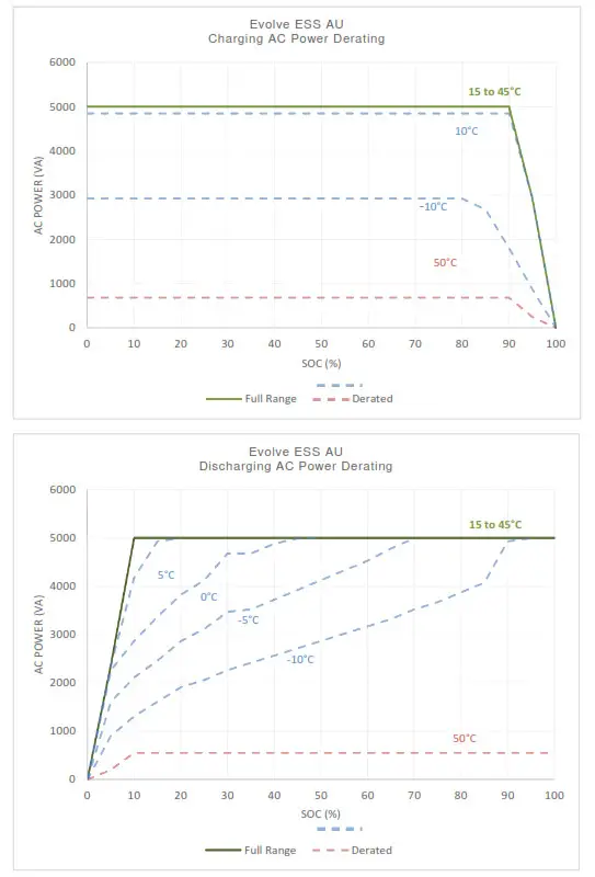 Figure 16: Energy storage system thermal derated charge and discharge curves with base (13 kWh) battery cabinet.
Appendix A: Electrical Block Diagram of Inter-Cabinet Wiring
The following reference diagram outlines the DC and communication interconnections between PCS, master battery, and expansion battery cabinets.
| Reference | P/N | Title | Notes |
| A1 | 8.01E+08 | PCS-BMS cable | Connects master battery to PCS [BMS CAN] port. |
| A2 | 8.01E+08 | BMS cable – short | Interconnects modules within same cabinet. |
| A3 | 8.01E+08 | BMS cable – long | Interconnects modules between cabinets. |
| A4 | – | Battery power cables | Positive / negative pair |
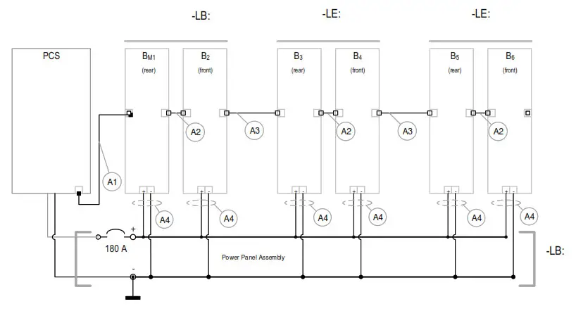 Figure 17: Electrical block diagram of the Evolve home energy storage system, including –LB / -LE cabinets with inter-cabinet wiring references.
Appendix B: Energy Meter Wiring Diagrams
B.1 Accu-Energy Acurev 1310
B.1.1 RS-485 Communication to the EMS
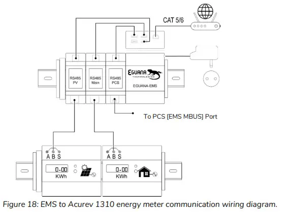 Figure 18: EMS to Acurev 1310 energy meter communication wiring diagram.
B.1.2(A) Main electrical panel meter CT and power wiring.
B.1.2(B) PV meter CT and power wiring.
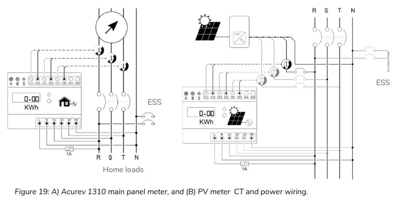 Figure 19: A) Akure 1310 main panel meter, and (B) PV meter CT and power wiring.
![]() THIS PAGE INTENTIONALLY LEFT BLANK
THIS PAGE INTENTIONALLY LEFT BLANK


