![]() EA-26000 Series EIS Back-up Battery System Panel
EA-26000 Series EIS Back-up Battery System Panel
Instruction Manual
EA-26000 Series EIS Back-up Battery System Panel
FAA APPROVED
CHICAGO ACO BRANCH
C & A DIVISION
Revision Log
| Revision | Pages Affected | Date of Revision | Description of Revision | Approved by | Date of FAA Approval |
| 00 | 11-Jan | 10/17/2022 | Initial Release | JMS | – |
| 01 | 3 | 12/14/2022 | Limitations Section Added | MAK |
Electroair EIS Back-up Battery System Panel
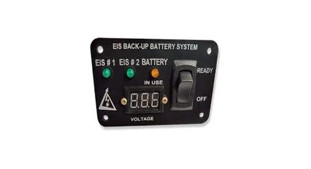
The EIS Back-up Battery System (EBBS) Panel has been created for operation with dual electronic ignition systems (EIS) using a back-up battery. The panel is to give the pilot indication of EIS status and back-up battery status during operation of an aircraft.
The EIS Back-up Battery System Panel is designed for use with Electroair Electronic Ignition Systems (EIS), STC# SA02987CH or SA03286CH, and TCW Technologies
Integrated Back-up Battery System (IBBS), STC# SA04400NY. The panel has three LEDs, a voltmeter, and a switch. Two LEDs (green) will indicate whether or not the connected EIS is receiving power. The remaining LED (yellow) indicates if the back-up battery is supplying power to one of the EISs. The voltmeter indicates the voltage of the back-up battery system. The rocker switch enables the back-up battery to supply power in the event of main power failure.

Limitations:
Electroair Electronic Ignition Systems STC# SA02987CH or SA03286CH must be installed prior to installation of EIS Backup Battery Panel System.
An approved Back-up Battery must be installed in accordance with the TCW Technologies Installation Instructions prior to installation of the EIS Back-up Battery System Panel. See table below for list of approved batteries.
| Battery P/N | Battery Mfg | STC# | Installation Document | Voltage |
| IBBS-12v3ah-CRT | TCW Technologies | SA04400NY | TCW doc # 725.0047 | 12V |
| IBBS-12v6ah-CRT | TCW Technologies | SA04400NY | TCW doc # 725.0047 | 12V |
| IBBS-24v3ah-CRT | TCW Technologies | SA04400NY | TCW doc # 725.0047 | 24V |
Kit Requirements and Contents
EA-26000-12 Kit Requirements:
- 12-volt electrical system
- Installed Electroair EIS STC# SA02987CH or SA03286CH.
- Installed TCW Technologies IBBS STC# SA04400NY.
EA-26000-24 Kit Requirements:
- 24-volt electrical system
- Installed Electroair EIS STC# SA02987CH or SA03286CH.
- Installed TCW Technologies IBBS STC# SA04400NY.
Other items needed:
- Basic tools and standard aircraft hardware required for mounting the panel
- Electrical tools for cutting, stripping, and terminating various wiring. Also recommended is a good selection of cable ties for harness routing and tie-off.
EA-26000-12 Kit Contents:
- EA-26000-12: EBBS 12 Volt Control Panel
- USB Drive Containing Kit Documents (Installation Manual, STC, ICA, AFMS, etc)
- Warranty Registration
EA-26000-24 Kit Contents:
- EA-26000-24: EBBS 24 Volt Control Panel
- USB Drive Containing Kit Documents (Installation Manual, STC, ICA, AFMS, etc)
- Warranty Registration
Receiving and Acceptance Checking of the EBBS Panel
- Review the packaging before acceptance from the freight carrier. If damaged, refuse the package.
- Open and check the contents of the package match the content listing on the package.
- Are all of the materials there?
a. Yes, proceed to step 4.
b. No, contact the factory. Have the serial number of the kit available when contacting. (factory 248-674-3433 or [email protected]) - Inspect the EBBS Panel for damage. If damaged contact Electroair 248-674-3433 or [email protected].
- Inspect the wires for nicks and cracks.
- Are all materials acceptable?
a. Yes, proceed with installation.
b. No, contact the factory. Have the serial number of the kit available when contacting. (factory 248-674-3433 or [email protected])
If possible, store parts in original packaging when not in use. If not possible, wrap parts in cushioning material and place in one location. Review above prior to reinstallation.
For latest copies of documentation, refer to www.electroair.net.
- AML
- AFMS
- ICA
- Installation Manual
- STC
Product Details and General Information:
Back-up Power Master Switch:
The EIS Back-up Battery System Panel has one switch connection as identified in the wiring diagram: Back-up Power Master Switch. This switch is a rocker switch located on the right side of the panel.
The back-up power master switch gives the pilot the ability to turn the back-up battery system off and it must be utilized to turn the back-up battery system off when not in use. In some installations this may be the only means to shut down the connected equipment.
The switch enables back-up power from the back-up battery system to be available on the output wires from the TCW Technologies IBBS when power on the normal aircraft bus falls below 11 volts (22 volts for a 24-volt system).
If the normal aircraft power bus is above 11 volts (22 volts for 24-volt system), then the outputs are energized with normal aircraft power (if the pass thru-power connections are utilized) and the back-up battery remains off-line. This operation occurs regardless of the state (READY or OFF) of the Back-up Power Master switch. This allows for automatic pass through of power during normal operation.
Back-up Battery Voltage Monitor
The EIS Back-up Battery System Panel has a voltmeter that will indicate the voltage of the back-up battery. The voltmeter will only report voltage when the back-up switch is in the “READY” position. A fully charged TCW battery will indicate about 13-14.7 volts (26-29.5 volts for 24-volt system. The working current of the voltmeter is less than 20mA.
Back-up Battery Status Indicator
The yellow LED labeled “BATTERY IN USE” located on the EIS Back-up Battery System Panel will indicate when the back-up battery is providing power which will occur when power on the normal aircraft bus falls below 11 volts (22 volts for a 24-volt system).
EIS Status LEDs
The EIS Back-up Battery System Panel includes two green LEDs labeled EIS #1 and EIS #2. These LEDs will turn on when the EISs are receiving power and turn off when the EIS is not receiving power. The POH should be updated to state which EIS is connected to the back-up battery and which is connected to main battery power.
Component Current Loads
| Component | Maximum Current Load |
| Voltmeter | 20mA |
| EA-26000-12 LEDs | 13mA |
| EA-26000-24 LEDs | 20mA |
Installation of EA-26000 EBBS Series
- Mounting the EIS Back-up Battery System Panel
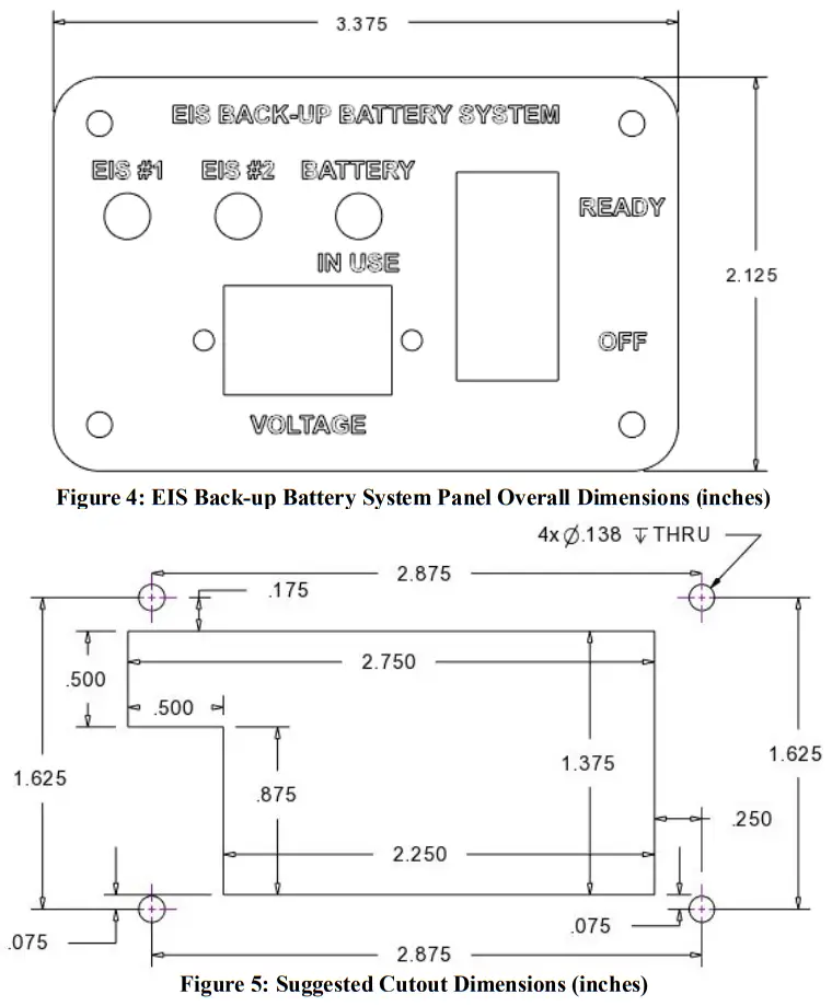
Determine the proper location for the panel and the most appropriate mounting method. The panel is 3.375 inches wide by 2.125 inches tall as shown in Figure 2. Suggested Cutout Dimensions are shown in Figure 3. Figures are not to scale.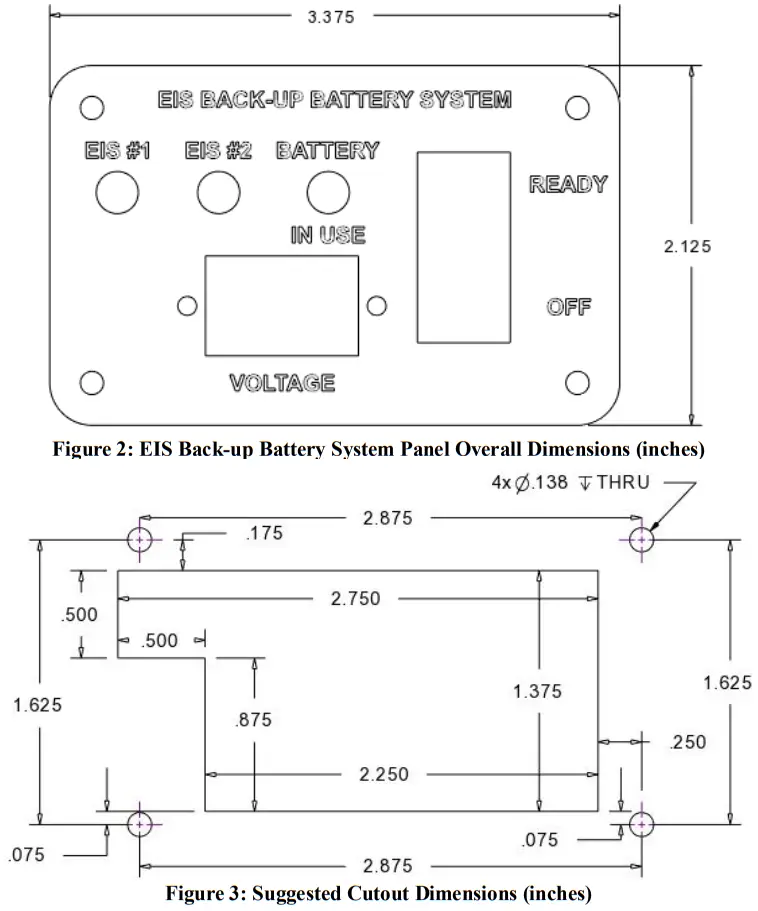
 CAUTION: Before cutting or drilling, verify space is clear behind the instrument panel.
CAUTION: Use extreme care as to not damage any wiring, instruments, structural, and fuel lines.
CAUTION: Ensure electrical connectors are tight on switch connections. Ensure wires will not pull out of any electrical connections. - Insert EIS Back-up Battery System Panel into instrument panel and screw down using standard hardware.
- Wiring for the components on the panel are explained in further steps 4-7. The panel components will have connection with the Electroair Electronic Ignition Systems and the TCW Technologies IBBS. Insulate any exposed electrical connections in accordance with 43.13-1B Change 1 section 11-159.
- Back-up Power Master Switch
The Back-up Power Master Switch is the rocker switch located on right side of the EIS Back-up Battery System Panel. Connect one terminal of the rocker switch on the panel to white/black wire (Pin 1) from the TCW Technologies IBBS Wire Harness. Connect to the other terminal of the rocker switch to ground. - Back-up Battery Voltage Monitor
Locate the wires from the voltmeter on the panel. Connect the red/green wire (Pin 2) from the back-up battery harness to the red wire of the voltmeter. Connect the black wire of the voltmeter to ground. Connect the white wire of the voltmeter in parallel to the output pin connected to the EIS controller and low voltage LED. - Back-up Battery Status/ Low Voltage Indicator
Find the yellow LED labeled “BATTERY IN USE” located on the EIS Back-up Battery System Panel. Connect the black wire of the yellow LED to the purple wire (Pin 3) of the back-up battery wire harness. Connect the red wire of the yellow LED in parallel to the output pin connected to the EIS controller. - EIS Status LEDs
The EIS Back-up Battery System Panel includes two green LEDs labeled EIS #1 and EIS #2. These LEDs will turn on when the EISs are receiving power and turn off when the EIS is not receiving power. The black wires of both LEDs should be connected to ground. The red wires should separately connect to the B+ wire at the EIS On/Off switches. The POH should be updated to state which EIS is connected to the back-up battery and which is connected to main battery power. - Function Check
a. Turn ON the aircraft main power.
b. Turn ON both EISs.
c. Verify both EIS (green) LEDs turn on.
d. Turn the rocker switch to the “READY” position.
e. Verify voltage of back-up battery turns on and “BATTERY IN USE” (yellow) LED remains off.
f. Turn main power OFF.
g. Verify the yellow LED turns on and one green LED turns off.
h. Turn the rocker switch to “OFF” position.
i. Verify all LEDs are off and voltmeter is off.
j. If verification passes, then return to service. If any verification fails, reverify and correct all connections and repeat Function Check. If the aircraft fails a second time, contact the factory for support. (248-674-3433 or [email protected])
Weights of Parts
| Part | Weight |
| EBBS Panel | 2 oz |
Product Mounting Footprint
Wiring Diagram
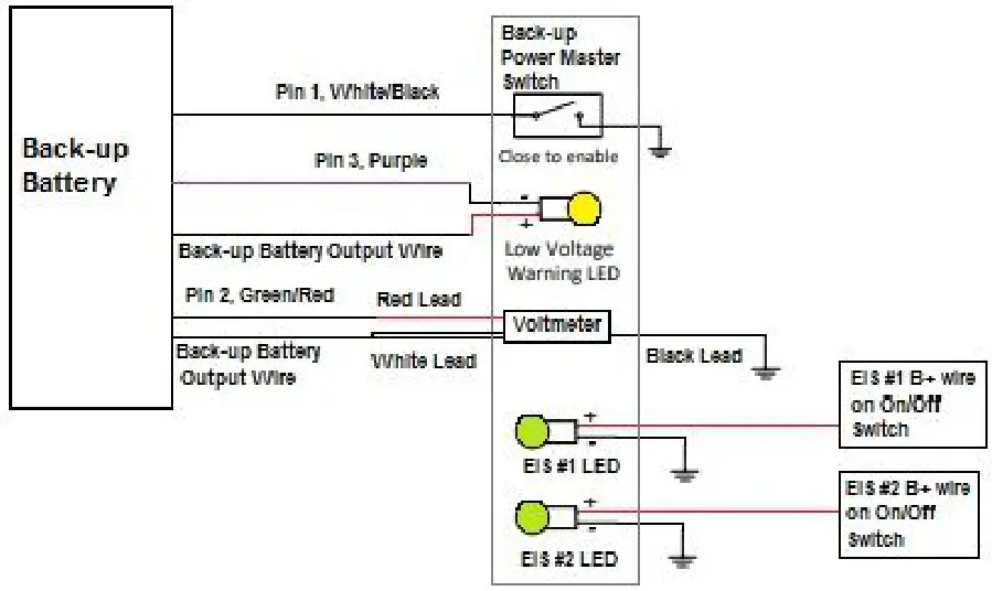 Figure 6: Wiring Connections for EIS Back-up Battery System Panel
Note: Figure 6 does not all connections shown for back-up battery of EISs. Refer to manufacturer instructions for those connections.
Glossary and Abbreviations:
| AC – Advisory Circular ACO – Aircraft Certification Office ACT – Action Identifiers AD(s) – Airworthiness Directive(s) AED – Aircraft Evaluation Division AFM – Aircraft Flight Manual AFMS – Aircraft Flight Manual Supplement Amdt – Amendment ALS – Aircraft Limitations Section AML – Approved Model List Amp – Ampere APP – Approval APU – Auxiliary Power Unit ASO – Applicant Showing Only BTDC – Before Top Dead Center CDL – Certification Data List CEA – Component Environmental Analysis CFR – Code of Federal Regulations CG – Center of Gravity COM – Communications Radio COTS – Commercial off the Shelf CSD – Compliance Summary Document CSTW – Crank Shaft Trigger Wheel DC – Direct Current DER – Designated Engineering Representative | DOC – Document Identifiers EBBS – EIS Backup Battery System EIS – Electronic Ignition System ELA – Electrical Load Analysis FAA – Federal Aviation Administration FHA – Functional Hazard Assessment FLM – Flammability Assessment GA – General Aviation HIRF – High-intensity Radiated Fields IAW – In-Accordance With ICA – Instructions for Continued Airworthiness Ignition Timing – is the process of setting the angle relative to piston position and crankshaft angular velocity that a spark will occur in the combustion chamber near the end of the compression stroke. LED – Light-Emitting Diode LH – Left Handed, used to indicated counter rotating Li-Fe-PO4 – Lithium-Iron-Phosphate LOPC – Loss of Power Control MAG – magneto MAP – Manifold Absolute Pressure MDL – Master Data List MEL – Minimum Equipment List MMEL – Master Minimum Equipment List MOD – Modification | MQP – Model Qualification Process MQR – Model Qualification Report MTH – Mag Timing Housing NAV – Navigation System OEM – Original Equipment Manufacturer PSCP – Project Specific Certification Plan P/N – Part Number QTY – Quantity POH – Pilot’s Operating Handbook REC – Recommend Approval RPM – Revolutions per Minute RTCA – Radio-Technical Commission for Aeronautics SAN – Structural Analysis SSA – System Safety Assessment STC – Supplemental Type Certificate TCDS – Type Certificate Data Sheet TDC – Top Dead Center TIA – Type Inspection Authorization TSO – Technical Standard Order TSOA – Technical Standard Order Authorization USC – United States Code VDC – Voltage Direct Current |
![]() Electroair
Electroair
5097 Williams Lake Road
Waterford, MI 48329 U.S.A.
Ph: 248-674-3433
Fax: 248-674-4231
Email: [email protected]
Electroair Acquisition Corp.
Revision 01
IM EA-26000
Prepared by: EAC


