![]() EA-26000 EIS Back Up Battery System Panel
EA-26000 EIS Back Up Battery System Panel
Instruction Manual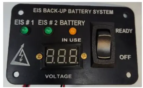 EA-26000
Instructions for Continued
Airworthiness
EA-26000 EIS Back Up Battery System Panel
Electroair
5097 Williams Lake Road
Waterford, MI 48329 U.S.A.
Ph: 248-674-3433 Fax: 248-674-4231
Email: [email protected]
Glossary and Abbreviations:
| AC – Advisory Circular ACO – Aircraft Certification Office ACT – Action Identifiers AD(s) – Airworthiness Directive(s) AED – Aircraft Evaluation Division AFM – Aircraft Flight Manual AFMS – Aircraft Flight Manual Supplement Amdt – Amendment ALS – Aircraft Limitations Section AML – Approved Model List Amp – Ampere APP – Approval APU – Auxiliary Power Unit ASO – Applicant Showing Only BTDC – Before Top Dead Center CDL – Certification Data List CEA – Component Environmental Analysis CFR – Code of Federal Regulations CG – Center of Gravity COM – Communications Radio COTS – Commercial off the Shelf CSD – Compliance Summary Document CSTW – Crank Shaft Trigger Wheel DC – Direct Current DER – Designated Engineering Representative DOC – Document Identifiers EBBS – EIS Backup Battery System EIS – Electronic Ignition System ELA – Electrical Load Analysis FAA – Federal Aviation Administration FHA – Functional Hazard Assessment FLM – Flammability Assessment GA – General Aviation HIRF – High-intensity Radiated Fields IAW – In-Accordance With ICA – Instructions for Continued Airworthiness Ignition Timing – is the process of setting the angle relative to piston | position and crankshaft angular velocity that a spark will occur in the combustion chamber near the end of the compression stroke. LED – Light-Emitting Diode LH – Left Handed, used to indicated counter rotating Li-Fe-PO4 – Lithium-Iron-Phosphate LOPC – Loss of Power Control MAG – magneto MAP – Manifold Absolute Pressure MDL – Master Data List MEL – Minimum Equipment List MMEL – Master Minimum Equipment List MOD – Modification MQP – Model Qualification Process MQR – Model Qualification Report MTH – Mag Timing Housing NAV – Navigation System OEM – Original Equipment Manufacturer PSCP – Project Specific Certification Plan P/N – Part Number QTY – Quantity POH – Pilot’s Operating Handbook REC – Recommend Approval RPM – Revolutions per Minute RTCA – Radio-Technical Commission for Aeronautics SAN – Structural Analysis SSA – System Safety Assessment STC – Supplemental Type Certificate TCDS – Type Certificate Data Sheet TDC – Top Dead Center TIA – Type Inspection Authorization TSO – Technical Standard Order TSOA – Technical Standard Order Authorization USC – United States Code VDC – Voltage Direct Current |
Revision Log
| Revision | Pages Affected | Date of Revision | Description of Revision | Approved by | Date of Approval |
| 00 | All | 10/20/2022 | Initial Release | JMS/MK |
Electroair has a process in place for updating designs and issuing Service updates. Service updates that affect ICA will initially be posted by a Service Bulletin and hen updated within the ICA as determined by both Electroair and the FAA, or as required by regulations. All updated ICA (including Service Bulletins) will be available at www.electroair.net or upon request.
List of Effective Pages
| Section | Page | Section Statu | Revision Level |
| Title | 1 | Original | 0 |
| Glossary and Abbreviations | 2 | Original | 0 |
| Revision Log | 3 | Original | 0 |
| Table of Contents | 5 | Original | 0 |
| Table of Figures | 5 | Original | 0 |
| Chapter 1 | 7-Jun | ||
| Section 01-00-00 | 6 | Original | 0 |
| Section 01-20-00 | 7 | Original | 0 |
| Section 01-25-00 | 7 | Original | 0 |
| Section 01-53-00 | 7 | Original | 0 |
| Chapter 4 | 8 | ||
| Section 04-00-00 | 8 | Original | 0 |
| Chapter 5 | 13-Sep | ||
| Section 05-00-00 | 9 | Original | 0 |
| Section 05-10-20 | 10 | Original | 0 |
| Section 05-20-20 | 11 | Original | 0 |
| Section 05-20-40 | 12 | Original | 0 |
| Section 05-50-20 | 13 | Original | 0 |
| Chapter 8 | 14 | ||
| Section 08-00-00 | 14 | Original | 0 |
| Chapter 20 | 15 | ||
| Section 20-00-00 | 15 | Original | 0 |
| Chapter 98 | 16 | ||
| Section 98-00-00 | 16 | Original | 0 |
Chapter 1
Section 01-00-00: Introduction
These are the accepted Instructions for Continued Airworthiness for the modification performed in accordance with the Electroair EA-26000 Series EIS Backup Battery System Panel STC# XXXXXX. All references to the EA-26000 in this document will refer to the EA-26000 series EIS Backup Battery System Panels and related components as specified in these Instructions for Continued Airworthiness (ICA). An STC Permission Letter and ICA should be supplied to the owner/operator of this STC at the time of completion. Subsequent accepted changes to the ICA will be available to owners and operator of this STC.
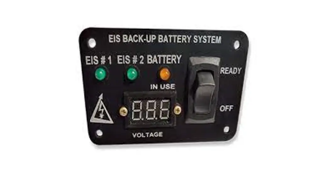
The EIS Back-up Battery System (EBBS) Panel has been created for operation with dual electronic ignition systems (EIS) using a back-up battery. The panel is to give the pilot indication of EIS status and back-up battery status during operation of an aircraft.
The EIS Back-up Battery System Panel is designed for use with Electroair Electronic Ignition Systems (EIS), STC# SA02987CH or SA03286CH, and TCW Technologies Integrated Back-up Battery System (IBBS), STC# SA04400NY. The panel has three LEDs, a voltmeter, and a switch. Two LEDs (green) will indicate whether or not the connected EIS is receiving power. The remaining LED (yellow) indicates if the back-up battery is supplying power to one of the EISs. The voltmeter indicates the voltage of the back-up battery system. The rocker switch enables the back-up battery to supply power in the event of main power failure.Figure 1: EIS Back-up Battery System Panel
The EBBS Panel must be installed using the current aircraft standards and practices as detailed in AC 43.13-2A/1B.
This ICA is intended to supplement the aircraft’s maintenance manual when the EBBS STC# XXXXXX is installed. The information, procedures, requirements, and limitations contained in this ICA for this type design change supersedes the information, procedures, requirements and limitations contained in the aircraft’s maintenance manual when this type design change is installed.
Section 01-20-00: Operation
The system is operated in accordance with AFMS EA-26000 Revision 00 or later FAA approved revisions.
Section 01-25-00 Structural Fasteners
Information required for fastener types, torque values, identification and discard recommendations are located in the installation manual IM EA-26000 REV00 or later FAA approved revision.
Section 01-53-00: Airframe Interface
This installation requires space to locate the EBBS panel where the pilot can appropriately see and operate the panel during flight.
Chapter 4
Section 04-00-00: Airworthiness Limitations
The Airworthiness Limitations section is FAA approved and specifies maintenance required under 14 CFR §§43.16 and 91.403 of the Federal Aviation Regulations unless an alternative program has been FAA approved.
EA-26000 Series Limitations are as follows:
- Electroair Electronic Ignition System STC # SA02987CH or SA03286CH must be installed.
- TCW Technologies Integrated Back-up Battery System STC# SA04400NY must be installed.
FAA Approved: ___________
Date:________________
Chapter 5
Section 05-00-00: General Information & Precautionary Statements
- Read this entire document before starting any processes listed within this document. If there are any questions or concerns, please contact Electroair before starting. (248-674-3433 or [email protected])
- If the EBBS panel is improperly installed or maintained; the EBBS, the aircraft, or the installer could be seriously damaged.
- Always use appropriate work and safety practices.
- For the latest up to date information refer to www.electroair.net (ICA, AML, Installation Manual, AFMS, etc.)
- For abnormal operation, or for a suspected failure, refer to the Section 05-50-20 of this document for Unscheduled Maintenance Checks.
- For service bulletins, or other product notes, review Electroair website (www.electroair.net).
- For ordering or questions about replacement parts, please contact Electroair. (248-674-3433 or [email protected])
Section 05-10-20: Time Limits, Airframe Components
General: This Chapter contains the time limit intervals for the airframe components from the EA-26000 series installation. This chapter is to be added to the approved scheduled inspection for the aircraft.
Airframe Components with Time Limits:
1. EIS Back-up Battery Panel: No service limit.
NOTE: Unscheduled Maintenance Tasks and/or Troubleshooting may point to one or more of these components requiring to be replaced.
Section 05-20-20: Scheduled Maintenance Checks, Airframe Components
- General: This Chapter contains the time limit intervals for the airframe components from the EA-26000 installation. This chapter is to be added to the approved scheduled inspection for the aircraft. If any part of the installation appears to be functioning improperly, consult Section 05-50-20 for Unscheduled Maintenance and Troubleshooting. If a major component is damaged or continues to malfunction, the component is question should be returned to the manufacturer for replacement.
- Airframe Components with Scheduled Maintenance Checks: These inspections are to be performed at the aircraft’s Annual Inspection or at the aircraft’s 100-hour inspection.
a. Wiring: Inspect all wire connectors and verify connections are securely attached and free from damage such as chaffing or excessive heat exposure.
b. Ground Connections: Inspect all ground connections and verify that they are competent and have continuity with the ground terminal on the aircraft battery or other acceptable ground buss.
c. Switch Panel: Inspect switch for proper operation; verify that EIS LED illuminate when EIS’s are in the ON position; verify the voltmeter is working proper and the reading is accurate. If any of these indications are not reading correctly, replace switch panel.
d. Placards: Inspect all placards and labels for existence and legibility. If placards no longer exist or are no longer legible, replace.
e. Fuses: If fuses were used as circuit protection devices in the installation of the EA-26000, inspect for the existence of readily accessible spare fuses. (Note: 14 CFR 91.205 (c)(6) applies when using fuses.) - Special Tools, Removal and Re-Installation of Airframe Components:
a. No special tools are required to work on an EA-26000 series panel.
b. For removal of any airframe component, follow installation manual IM EA26000 REV00 or later FAA approved revision.
c. After reinstallation, verify the operation of the panel by performing a normal start per the aircraft’s Flight Manual or Pilot’s Operating Handbook AND the AFMS EA-26000, REV 00 or later FAA approved revisions.
Section 05-20-40: Special Inspections, Airframe Components
- General: This section contains requirements for special inspections of the EA26000 series panel. Conditions may arise from incidents or accidents that warrant additional, special inspection of the EA-26000 series panel. A Special Inspection is required if the aircraft is subject to total immersion in water, lightning strike, or fire. If any part of the installation appears to be functioning improperly, refer to Section 05-50-20 for Unscheduled Maintenance and Troubleshooting of the system. If a major component in question is damaged or continues to malfunction, the component in question should be returned to the manufacturer for replacement.
- Total Immersion in Water: Inspect switch panel I.A.W. Section 05-20-20 of this ICA. Replace if necessary.
- Lightning Strikes: Inspect switch panel I.A.W. Section 05-20-20 of this ICA. Replace if necessary.
- Airframe or Engine Fire: Inspect switch panel I.A.W. Section 05-20-20 of this ICA. Replace if necessary.
Section 05-50-20: Unscheduled Maintenance Checks/Troubleshooting, Airframe Components
- General: This section contains requirements for unscheduled maintenance checks and troubleshooting of the Airframe Components of the EA-26000 series. Conditions may arise from time to time that warrant additional, unscheduled inspection of the EA-26000. This section will identify some of those conditions requiring unscheduled maintenance checks of the EA-26000 series panel and is to be used if the Electroair system is suspected to be the fault or appears to be functioning improperly. If a major component in question is damaged or continues to malfunction, the component in question should be returned to the manufacturer for replacement.
- Condition #1 Switch Panel LEDs do not illuminate. This is indicative of a bad connection.
a. Verify all connections are secure. Correct as necessary.
b. Verify charging power is being supplied. Correct as necessary.
c. Contact Electroair for further troubleshooting procedures. - Condition #2 Any other anomalies. For any anomalies not covered in this section, refer to Section 05-20-20 and perform all of the scheduled maintenance requirements to clear the problem. Contact Electroair if problem persists.
Chapter 8
Section 08-00-00: Weight and Balance Information
General: The installation of the EA-26000 series panel results in a change to the aircraft’s weight and balance. A new weight and balance should be calculated for the aircraft after the installation of the EA-26000. All future loading calculations should use the updated aircraft weight and balance. The individual part weight and dimensions are below.
Part …………………EIS Back-up Battery System Panel
Weight…………………………… 2 oz
Product Mounting Footprint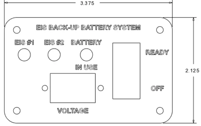 Figure 2: EIS Back-up Battery System Panel Overall Dimensions (inches)
Chapter 20
Section 20-00-00: Standard Practices Airframe
General: These are the accepted Instructions for Continued Airworthiness for the modification performed in accordance with the EA-26000 Series STC# XXXXXX. All references to the EA-26000 in this document will refer to the EA-26000 Series Panels (EA-26000-12 and EA-26000-24) and related components as specified in these Instructions for Continued Airworthiness (ICA). Performance of this ICA does not require any special training or practices outside of the Standard Practices and Methods outline in FAA AC43.13-1B, Acceptable Methods, Techniques and Practices. All tasks outlined here should be performed by a person or persons possessing a valid A&P License issued by the FAA, or equivalent issued document under the appropriate governing Airworthiness Agency. Subsequent accepted changes to the ICA will be available to owners and operator of this STC through www.electroair.net.
Chapter 98
Section 98-00-00: Wiring Diagrams for EA-26000 Series Panels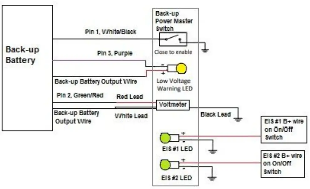 Figure 3: Wiring Connections for EIS Back-up Battery System Panel
Note: Figure 3 does not all connections shown for back-up battery of EISs. Refer to manufacturer instructions for those connections.
![]() Electroair Acquisition Corp. Revision 00
Electroair Acquisition Corp. Revision 00
ICA EA-26000 Prepared by: EAC


