AMPLENESS Home Energy Storage System Split Type 
Security Disclaimer
Users must read this chapter carefully and operate it according to the safety precautions required by this chapter before installing, using and repairing the battery. Our company will be responsible for nothing if it happens to any injuries and loses caused by improper operations.
Attention It may cause moderate injury or minor injury to human beings, or even damages to product because of the danger caused by failure to operate as requirements.
Danger It may cause fire or serious personal injury, or even death because of the danger caused by failure to operate as requirements.
Precautions for Safe Use
We feel quite thankful that you choose AMPLENESS Home Energy Storage System (Split Type). In order to enable you to use and maintain it in a better way, please kind read this user manual carefully before use.
|
Unpacking Examination | Attention |
| 1. Please don’t install the battery if it is found damage or lack of parts. Otherwise, it may be malfunction. 2. Please don’t install battery and connect with supplier in time if the packing list doesn’t same as that of the real one. | |
|
Installation | Danger |
| 1. The wiring work must be performed by the qualified electrical personnel, otherwise there will be a danger of electric shock or damage to product; 2. Please ensure that the power is cut off before wiring, otherwise, there will be a danger of electric shock or catching fire. 3. The installed cables must be meet requirements, and the part of power distribution must comply with safety regulations. 4. Please carry out the installation strictly in accordance with the installation steps in the following chapters, otherwise it will cause the damage to product; | |
| Attention | |
| 1. Please lift and put it down gently to avoid hurting feet or damage to product during transportation and installation. |
| 2. Please keep battery away from the flammable objects and heat sources. 3. Please don’t drop any sundries into battery during installation. Otherwise, it may cause system error. | |
|
Working | Danger |
| 1. Please don’t directly plug or unplug the DC input socket or other sockets like the terminal block socket, input socket and output socket to avoid the danger of electric shock. 2. Please don’t directly open the battery shell to avoid the danger of electric shock. | |
| Attention | |
| 1. Please ensure that the battery will be work within the allowable range before operating to avoid damage to product. 2. Please ensure that the battery is fully charged and the power is cut off if it is not used for a long time, to the electricity power is empty due to long-term standing. 3. Please charge the battery regularly and disconnect the switch after the charging is completed if the product is not used for a long time. | |
|
Maintenance and Overhaul | Danger |
| 1. Please ensure to disconnect the DC input, DC output and switch before disassembling the shell, to avoid the danger of electric shock. 2. Please don’t touch directly the exposed parts of circuit to avoid the danger of electric shock, as there is still residual electricity inside the battery even after the shell is disassembled. 3. Please ask the professional personnel to perform the maintenance and overhaul. Please don’t disassemble the battery by yourself. Otherwise, it may cause product damage and personal injury. | |
|
Transportation | Danger |
| 1. Please avoid strong vibration, falling and bumping during transportation. Don’t place the package upside down. Don’t lose any accessories and user manual when unpacking package or transporting battery. | |
| Attention | |
| 1. Please be careful of your security and avoid hurting yourself in transportation. | |
|
Others | Danger |
| 1. Please don’t modify the system by yourself to avoid happening serious accidents. 2. Please immediately cut off the switch and input/output cables if it happens to abnormal conditions inside the system. 3. Please cut off all switches and put out the fire by using dry powder extinguisher if battery catches fire. |
Manual Instruction: The Home Energy Storage System (Split Type) provides the energy storage for PV users and backup power support for the important electrical equipment. The battery system can store excessive power generated by PV system at daytime, and can utilize the stored energy (if necessary) to supply power for electrical equipment at night, thus improving the utilization efficiency of photovoltaic power generation, shaving peaks and filling valleys, providing backup power for emergency and important electrical equipment to avoid data and financial loss caused by sudden power outage.
The user manual introduces battery details like the basic structure, parameters, procedures and methods of installation, operation and maintenance.
Product Introduction
The split type battery is a kind of energy storage product based on 51.2V lithium iron
phosphate battery. This product configured a customized battery management system (BMS) is designed according to the energy storage requirements of home PV users. The battery system can store excessive power generated by PV system at daytime, and can utilize the stored energy (if necessary) to supply power for electrical equipment at night, thus improving the utilization efficiency of photovoltaic power generation, shaving peaks and filling valleys, providing backup power for emergency, etc.
Support Large-capacity Energy Storage
Multiple batteries can be connected in parallel to enlarge capacity.
High Reliability System
Adopting high-performance processor and configuring a customized BMS protection board to guarantee the system can operate stably.
Monitoring battery conditions in real-time. Providing many functions like short circuit protection, reverse polarity protection, high voltage protection, low voltage protection, over-current protection in charge, over-current protection in discharge, overcharge protection, over-discharge protection, high temperature protection, low temperature protection, balance cells, etc.
Strong Communication Function
Configuring multiple communication interfaces: RS-485, CAN; Knowing battery working status at any time through the master computer.
Multiple cascades: Obtaining address automatically; Non-human operation.
Leading Advantages in Product
Supporting charge and discharge by large current, 85A (1C) charging and discharging modular design, Small volume, Light weight, adopting multi-level energy consumption management, Operation and wiring on front panel, Easy to installation and maintenance; Excellent compatibility; Seamless connection between BMS and inverter; More convenient operation in one switch; Suitable for long-term cycles of charge-discharge.
Specification
Battery Specification
| Type | Parameters | |
| Inverter Input (AC/DC) | Rated input voltage | 54.4V |
| Input voltage range | 36V≤U≤60V | |
| Input current | ≤85A | |
| Input power | <5000W | |
|
System Output(DC) | Nominal output voltage | 51.2V |
| Output voltage range | 44.8V<U<58.4V | |
| Output current | ≤85A | |
| Output power | <5000W | |
| Output overload | Protection board is outage and | |
| stops discharging power if current is over 110A and lasts 10S. | ||
| Short circuit | System shuts down automatically | |
| PACK Capacity | 85Ah | |
|
Production Board Function | Provide over-charge protection, over-discharge protection, over-current protection, high-temperature production, short circuit protection, etc. | |
| Battery Type | Quadrate lithium iron phosphate battery | |
| Working Temperature | Charge | 0℃-55℃ |
| Discharge | -10℃-55℃ | |
| Relative Humidity | ≤90% | |
| Dimension | [500mm(L)×446mm(W)×312mm(H)]±2mm(Not include bulge part) | |
| Weight | ≤77±2Kg(Subject to real battery) | |
Attention: The continuous charge/discharge current of each battery should ≤85A to guarantee battery the best using performance.
Product Standard Configuration
| Name | No. | Unit | Specification | Remark |
|
Home energy storage system(split type) |
1 |
set | LiPO4 Cells, capacity 51.2V/85Ah, BMS, reserve 1 CAN and 2 RS485 interfaces, LED indicators, metal shell coated with insulating materials | |
| Output power cable | 2 | section | 25 mm², 3 meters long | |
| Parallel power cable | 2 | section | 25 mm², used in parallel | |
| Output communication cable(network line) | 1 | section | shielded Twisted Pair (STP), 3.5 meters long | |
| Product parallel line | 1 | section | shielded Twisted Pair (STP), 0.35 meters long |
Accessory List
| Name | No. | Unit | Specification | Remark |
| Ground wire | 1 | section | 4 square, yellow and green | |
| Nuts, Screws, Bolts | 1 | set | / |
Function Description
Physical Figure of Front Panel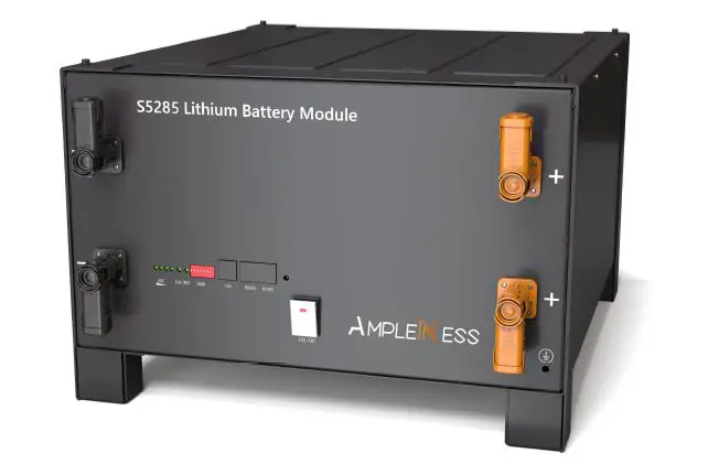
Front Panel Schematic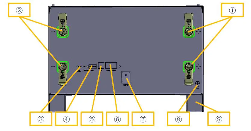
Parts Description
| NO. | Name | Function | Remark |
| 1 | Positive electrode | connect the positive electrode of external device | |
| ② | Negative electrode | connect the negative electrode of external device | |
| ③ | Capacity indicator, alarm indicator | Indicate working status, battery capacity | |
| ④ | Address DIP switch | Change product code when multiple units are connected in parallel |
| ⑤ | CAN interface | Connect external device | |
| ⑥ | RS485 interface | Connect external device | |
| ⑦ | Battery switch | Battery switch | |
| ⑧ | Ground point | Avoid accidental leakage of electricity | |
| ⑨ | Support rack | Fix product on the support |
Battery Management System (BMS protection board) Function
Voltage Protection Function
| Discharging low-voltage protection | Charging over-voltage protection |
| In discharging, the over-discharge protection will start and battery stops to supply electricity if the voltage of any single cell is lower than the protection value. The protection will be dismissed after the voltage of all cells returns to the range of rated hysteresis value. | In charging, the system will stop charging if the voltage of battery module or any single cell reaches to the protection value. The protection will be dismissed after the battery module voltage and cell voltage return to the range of rated hysteresis value. |
Current Protection Function
| Charging over-current protection | Discharging over-current protection |
| System stops charging if charging current is over the protection value. Protection is dismissed after a period of time. Please pay attention that the maximum charging current shouldn’t exceed to the protection value when using the battery. | System stops discharging if discharging current is over the protection value. Protection is dismissed after a period of time. Please pay attention that the current required by electrical equipment shouldn’t exceed to the protection value when using the battery. |
Temperature Protection Function
| Charging low/over-temperature protection | Discharging low/over-temperature protection |
| In charging, system starts charging temperature protection and stops charging if the battery temperature is over protection range, and dismisses protection after temperature returns to rated hysteresis value. | In discharging, system starts discharging temperature protection and stops supplying electricity if the battery temperature is over the protection range, and dismisses protection after temperature returns to rated hysteresis value. |
Other Protection Function
| Short circuit protection | Automatic shutdown |
| System starts short circuit protection if it occurs to short circuit when battery starts working from a shutdown state. | Battery will shut down automatically after it has no external loads and power supply for 48 hours. |
Running Environment
| Running Environment | Condition |
| Working temperature | 0℃ – 50 ℃ |
| Relative humidity | 5% – 95% ,no condensation |
| Altitude | 2000m |
| On-site environment | Away from heat source, avoid direct sunlight, no corrosive gas, no explosive gas, non-destructive insulation gas, non-destructive insulation conductive dust |
Requirements of Package, Transportation, Storage
| Items | Methods | Requirements |
|
Transportation | Transport | Please avoid violent vibration, impact or extrusion, and protect it from sun and rain during transportation. |
| Loading and unloading | Please move it gently, and avoid falling, tumbling and pressing. | |
|
Storage | Storage environment | Storage temperature:-20 ℃~55℃;relative humidity ≤85%;Stored in the clean, dry, ventilated room and avoid the direct sunlight. |
| Gas environment | Please prohibit harmful gas, flammable and explosive products, corrosive chemicals. | |
| Away from danger | Please keep away from corrosive substances, fire and heat sources | |
| Battery storage SOC | 20%–50% | |
| Long-term storage | Storage for more than 6 months, please ensure that the battery is charged for more than 80% capacity before storage, and charged once every 6 months with over 80% supplementary power. |
Installation and Configuration
Installation Preparation
Security regulations
Only those people who master the knowledge of power-supply system and electricity precautions are allowed to install this device. In installation, please always observe the local safety regulations and meet the security requirements listed below.
Please ensure that the battery is uncharged and in shutdown state before installing or disassembling it.
Please ensure that the power distribution cables are routed properly and have protection, avoiding touching these cables when people operate the device.
Running environment examination
The running environment should meet the above referred requirements. If it is not as request, please rectify it and re-examine running environment.
Tools and data
Required tools and instruments are as following form:
| Name | Remark |
| Multimeter | Examine product status. Please avoid operating it with electricity. |
| Screwdriver (slotted, cross) | Disassemble, install screw bolt |
| Wrench | Fix the bracket |
| Diagonal pliers | Cut off cables |
Technical Preparation
| Electrical interface setting | Security examination |
| Please kind do the following examination if the battery connects with the user’s device directly: Check whether the DC charging interface of inverter meets requirements of specification, voltage, current of battery pack. Check whether power of electrical device matches with the parameters of battery pack. | Fire-fighting equipment should be prepared near the battery, like, the portable dry powder fire extinguisher. It is strictly forbidden to place flammable, explosive and other dangerous items next to the battery. |
Installation Instruction
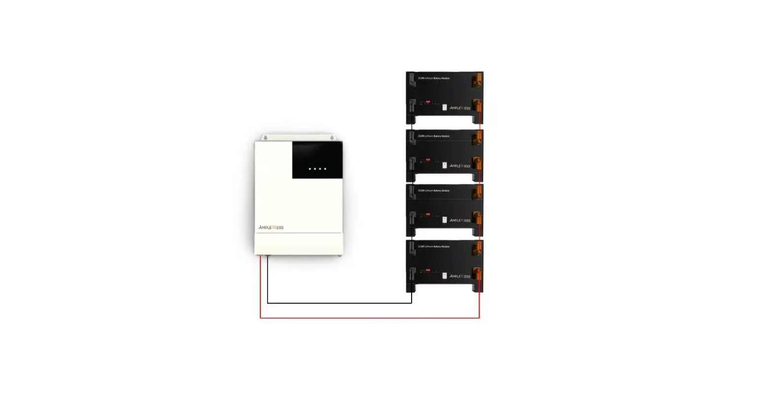
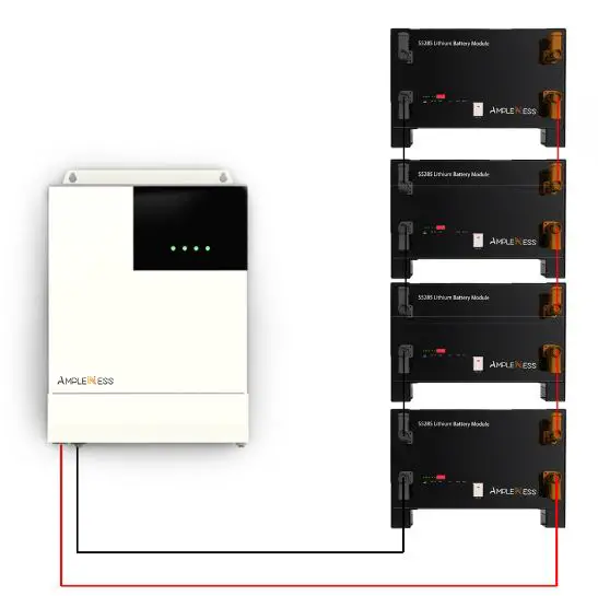
Please take reference for the structure diagram of split type battery. The product includes battery module and fixed bracket. For using one battery alone, you just need to connect with an inverter by placing the product on flat ground.
For using in parallel, the battery packs can be stacked up to 4 layers.
Limit points are designed on top of and at bottom of battery bracket, which can strengthen stability and practicality, thus avoiding the danger of accidental displacement, side slip and others in working.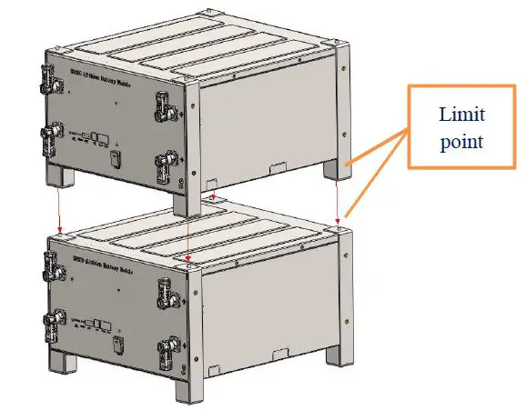
Unpacking
Please unload the product as requirements and prevent it from sun and rain when the device arrives at installing site. Before unpacking, please check the total number of materials in 【Shipping List】attached on package, and check whether is package is well packed or not.
In the process of unpacking, please pay attention to lift and put it down gently and
protect its surface coating.
The installing person should read technical document, check the list, confirm whether accessories are completed and intact according to【Configuration Table】and【Packing List】 at first after unpacking. If internal packages are damaged, please check it carefully and take records.
Preparation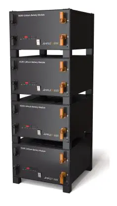
- Please ensure the POWER buttons of all batteries are in cut-off status.
- Please ensure the charging voltage of the device is within the product allowable range.
- Please cut off power to all related devices.
Installation and wiring
Device installation
Please take reference of the way recommended by manual to place the product. All devices must be firm during installation. Please arrange the stacked number of devices flexibly as actual needs. Don’t install batteries on sloping and unstable ground.
Ground wire connection
Please unscrew the screw at the ground hole on front panel, install the ground terminal on the screw and tighten it with a screwdriver. The other end of ground wire is connected to the nearby bracket, and the whole is connected to a reliable ground point.
Attention: the ground resistance <4Ω.
Power cable connection
Please check the continuity of the cable, distinguish the positive and negative terminals, and label the cables before connecting power cable. Please also check whether there is short circuit and reverse connection after the cable connection is finished. The checking method is as follows:
Cable continuity: please adjust to the buzzer gear of multimeter and test two ends of the cable by a probe. If the buzzer sounds, the cable is available.
Voltage diagnosis: please adjust to the DC voltage gear of multimeter and test the positive and negative electrode of battery by a probe. If it indicates the voltage within the normal range, the product can be used.
Cables connection
Please take reference of the following description of wiring method for installing battery pack.
A single battery: please connect the positive electrode of battery with the DC positive electrode of inverter by a red cable, and connect the negative electrode of battery with the DC negative electrode of inverter with a black cable.
Multiple batteries: please adopt the parallel connection method between battery and battery or battery and inverter. At first, please connect the positive terminals of the adjacent 2 batteries respectively by a red cable, and connect the negative terminals of the adjacent 2 batteries respectively by a black cable. Second, please connect the positive electrode of battery with the DC positive electrode of inverter by a red cable, and connect the negative electrode of battery with the DC negative electrode of inverter by a black cable.
Communication cable, please connect the CAN interface of battery with the communication interface of inverter. The RS485 interface of battery is used for the communication connection of two batteries.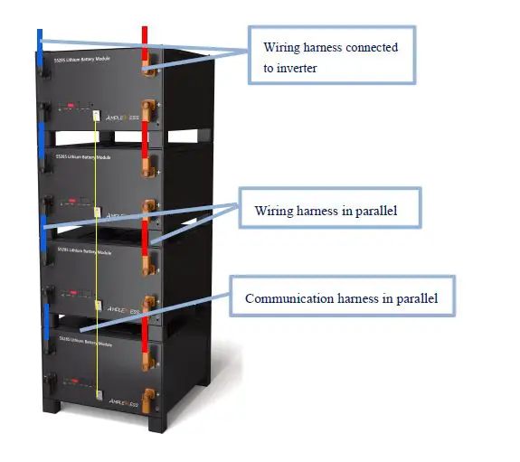
Communication wire connection
A single battery: just select the corresponding interface according to the communication protocol of inverter.
Multiple batteries: the host and the slave batteries communicate in cascade mode, thereinto, one of them is the host, and the rest are slave batteries. Please take reference for cascade wiring of the above map. Then, the corresponding port can be connected to the host battery according to the communication protocol of inverter.
Start-up
- Please confirm again whether all cables are correctly connected, firmly connected, and not short circuit or reverse connection before starting up.
- Please turn all battery switch buttons to “ON”.
- A single battery: If the battery SOC indicator is always on and the alarm indicator is off, it means that the battery has been started.
- Multiple batteries: If all battery SOC indicators are always on and the alarm indicator is off, it means that all batteries have been started.
Attention: please connect the inverter immediately to charge if battery power is too low and cannot be started.
Power-on test
- Please connect battery and inverter or DC switching power supply.
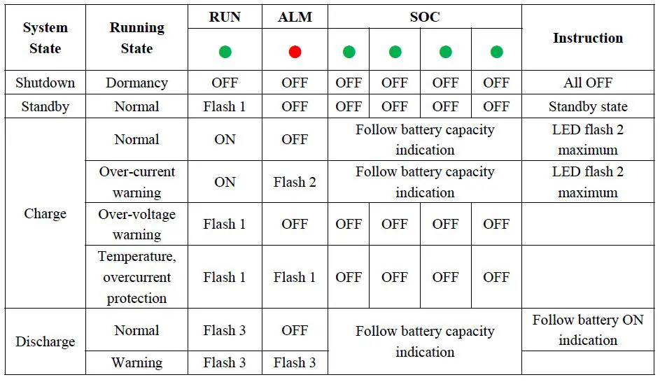
- Please check whether battery state is normal according to the indicator table:
- battery will be in charging mode if battery power is not full and inverter has successfully charged to battery.
- battery will be in standby mode if battery power is full and is not supply power to loads.
- battery will be in discharging mode if battery is supply power to loads.
Communication Settings
The product is designed with communication interfaces like the RS485 and CAN, and the battery status can be easily obtained or the internal parameters can be modified through the master computer.
RS485 interface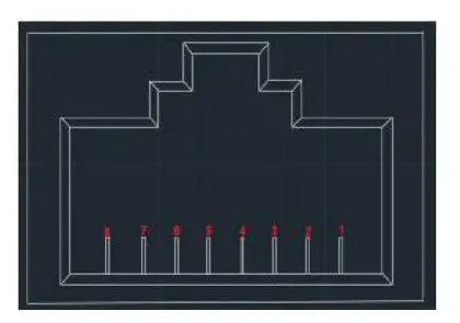
| Pin | Definition |
| 1、8 | Ground |
| 2、7 | RS485-B |
| 3、6 | RS485-A |
| 4、5 | NV(hanging) |
The product has RS485 communication between battery packs, and baud rate is
19200bps. Please take reference for the above figure of communication interface definition.
CAN interface
The product has the CAN communication function between battery packs and inverter, and baud rate is 500K. Battery can communication with the inverter and CAN TEST by connecting with standard network cables, and the current battery information can be uploaded to the related device.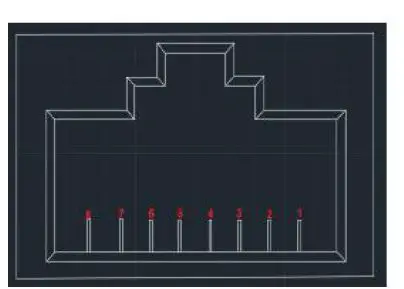
| Pin | Definition |
| 1、2、7、8 | NV(hanging) |
| 4 | CAN-H |
| 5 | CAN-L |
| 3、6 | Ground |
Abnormal Conditions and Fault Handling
Fault and abnormal phenomenon handling
| Fault Phenomenon | Fault Causes | Handling Method |
| DC input fault | No DC input voltage | Please check whether DC input switch is closed, check whether circuit is open |
| Battery fault | No battery DC output | Please check whether switch is closed, check whether circuit is open |
| Overload | Too large power or short circuit | Please confirm whether load is less than the rated power, check whether load is short circuit |
| Abnormal temperature inside system | Over temperature inside box | Please turn off the load and restart it after temperature drops, check |
| whether ambient temperature exceeds the standards | ||
| Low battery | SOC too low | Please charge the battery |
| System fault | System operation error | Please cut off load, shutdown switch, and restart battery |
The split-type battery is designed with indicators on the upper panel, and has perfect protection function. Battery system will stop to output power and indicators will indicate the abnormal condition once the abnormality or failure occurs.
Maintenance and Recycling
Frequent maintenance is required in order to ensure the continuous and normal operation of battery, and recycling of old equipment is also required in order to settle the environmental protection issues.
Operation environment
The installation and storage of battery should avoid the environment of high corrosiveness, high dust, high temperature and high humidity, especially avoid metal substances falling into the box.
Security examination
Please check regularly whether connecting line is aging, and whether connection point of cable is tight and safe.
Maintenance requirement
Please cut off power supply completely before opening the box for maintenance. Please don’t damage parts and components when disassembling, and pay attention to the sequence of wiring. Please also perform maintenance by wearing insulting gloves and using insulting tools.
Specific requirements of maintenance
Please clean the dust and debris in box, and check whether the terminals and screws in box are fastened, whether traces left and damaged components by overheating in the box. Please refer to user manual to deal with problems when the battery is in fault and cannot work normally. If the problem still cannot be solved, please contact with the dealer or the manufacturer as soon as possible. Don’t disassemble parts by yourself.
Battery Recycling
About the information on proper disposal of old battery, please contact with your local recycling center or hazardous waste disposal center. Please don’t discard battery into fire as it may lead to the danger of explosion. Please take reference for your local regulations about battery disposal requirements and dispose the wasted battery properly. Don’t disassemble battery randomly as the released electrolyte is harmful to your skins and eyes, and it even has toxic. Please don’t discard battery into trash. For more detailed information, please contact with your local recycling/reuse center or hazardous waste disposal center. Don’t discard the wasted electrical or electronic devices into trash. Please contact your local recycling/reuse center for proper disposal;
Legal statement
The copyright of the manual belongs to SUZHOU AMPEL ESS CO., LTD. Any unit, company or individuals is not allowed to extract, copy and translate it in any way without the written permission of copyright owner. Otherwise, infringement must be investigated.
The user manual doesn’t grant readers the permission and rights to use any marks showing in the manual in any method without the prior written agreement of SUZHOU AMPEL ESS CO., LTD or owner of manufacturer’s trademark or trade name.
The product complies with the requirements of environmental protection and personal safety. The storage, use and disposal of product should be carried out in accordance with the product manual, relevant contracts or laws, regulations.
You can check relevant technical information through Ample ESS website when there are product updates and technical changes.
Suzhou Ample Ess Co., Ltd
Add:SND, Suzhou City, Jiangsu Province, China
Tel:0512-68418695


 Solar Storage System User Manual")


