![]()
WEB-REV 5.21
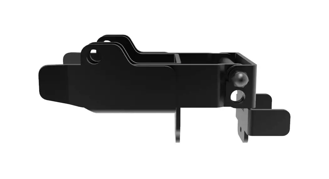
Y-LATCH KIT
Installation Instructions
 Read all instructions prior to installing product.
Refer to manufacturers safety instructions when operating any tools.
To register your product, please visit: barretteoutdoorliving.com
WARNING:
- Improper installation of this product can result in personal injury. Always wear safety goggles when cutting, drilling and assembling the product.
- Incorrect installation may cause harm to the gate or individual.
- Not pool code approved.
- Do not allow children to play with the gate.
NOTICE:
- DO NOT attempt to assemble the kit if parts are missing or damaged.
- DO NOT return the product to the store, for assistance or replacement parts call: 1-877-265-2220.
BEFORE YOU BEGIN:
Please read the instructions completely before assembling.
Retain manual and your dated sales slip for future reference or warranty claims.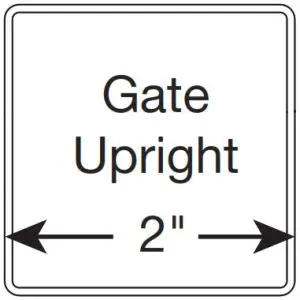
TOOLS NEEDED:
| Gate | |
| #2 Square/Phillips Screwdriver | |
| Safety Glasses | |
| Tape Measure | |
| Pencil | |
| Drill |
Component list:
| QTY | Description |
| 1 | Y-Latch |
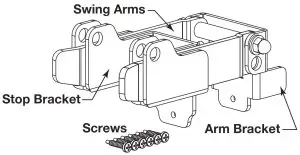
| 12 | Stop Bracket |
| 6 | 1″ #2 Square/Phillips Combo Self-Tapphig Pan Head Screws |
To obtain and review a copy of the warranty please visit: barretteoutdoorliving.com. You may also contact us at 1-877-265-2220 or email Cs.[email protected]
DOUBLE DOUBLE DRIVE GATE INSTA
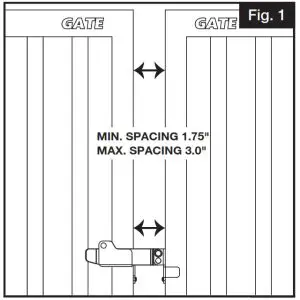
- Determine Gate Opening:
Determine the gate opening by adding the width of the gates plus clearance of hinges plus a clearance distance of 1-3/4″ to 3″ for the Y-latch (Fig. 1). (See hinge instructions for clearance details.)
NOTE:
Mount gate on hinges prior to installing the Y-latch.
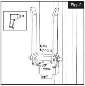
- Attach lf–Latch to Fence Gate:
Place and hold Y-latch on gate upright. Attach Y-latch to gate upright with three self-tapping pan head screws (Fig. 2).
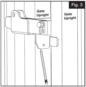
- Determine Location of Stop Bracket:
While the swing arms are lowered and leveled, place stop bracket flat on the gate while moving the bracket up or down until the swing arm is level. Once the swing arm is level, mark with a pencil the stop bracket location on the side of the gate (Fig. 3).
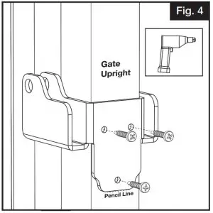
- Attach Stop Bracket to Gate: With the gate opened, place stop bracket on the gate and align with the pencil mark. Attach stop bracket to gate with the remaining three self-tapping pan head screws (Fig. 4).
WALK GATE INSTALLATION
- Determine Gate Opening:
Determine the gate opening by adding the width of the gate plus clearance of hinges plus a clearance distance of 1-3/4″ to 3″ for the Y-latch.(See hinge instructions for clearance details.)
NOTE:
Mount gate on hinges prior to installing the Y-latch. - Attach Y–Latch to Fence Gate:
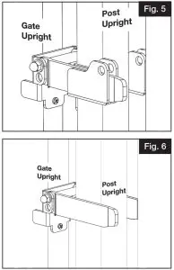
a. For walk gates utilizing 2″ gate uprights and 2″ post uprights, the Y-latch can be installed in the same method as the double drive gate installation (Fig. 5).
b. For walk gates utilizing 2″ gate uprights and 21/2″ post uprights, the post will serve as the Y-latch swing arm stop.
NOTE:
Do not install the stop bracket because it will not fit on post upright (Fig. 6).
PADLOCK OPTIONS
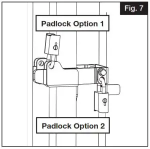
- Fig. 3, 4 and 5 Y-latch installation should use padlock option 1 shown in Fig. 7.
- Fig. 3, 4 and 5 Y-latch installation should use padlock option 1 shown in Fig. 7.
![]() Barrette Outdoor Living
Barrette Outdoor Living
7830 Freeway Circle, Cleveland, OH. 44130
barretteoutdoorliving.com • (877) 265-2220


