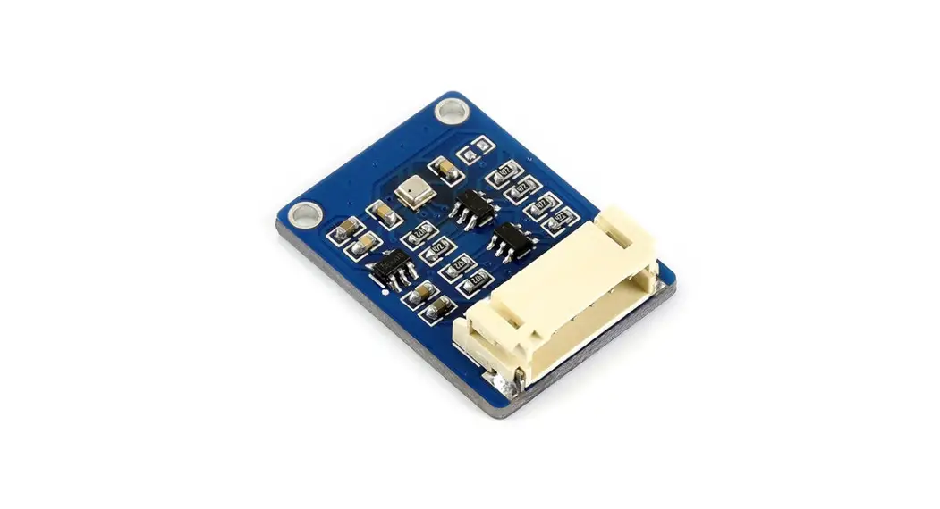
![]() QIA128 Digital Low Power Controller with SPI and UART
QIA128 Digital Low Power Controller with SPI and UART
User Guide
General Description
The QIA128 is a single-channel ultra-low-power digital controller with UART and SPI outputs.
Pin Configurations and Function Descriptions
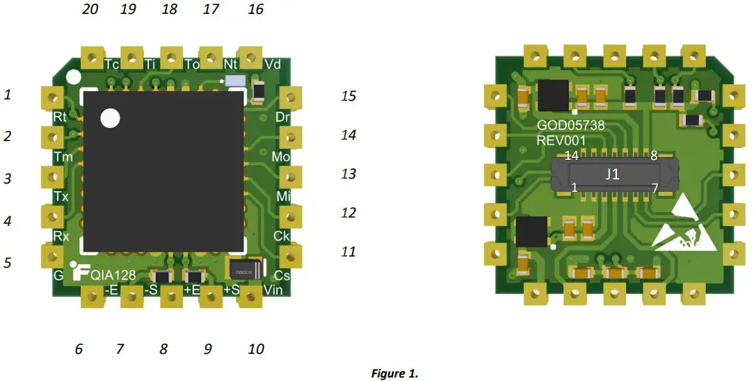 Table 1.
| # | Pin | Description | J1 # |
| Active low reset pin. | – | ||
| 2 | TMS | JTAG TMS (Test Mode Select). Input pin used for debugging and download. | – |
| 3 | TX | Transmit Asynchronous Data output. | 7 |
| 4 | RX | Receive Asynchronous Data input. | 6 |
| 5 | GND | Ground pins are connected to each other internally. | 1 |
| 6 | – Excitation | Sensor excitation return (connected to Ground). | 2 |
| 7 | – Signal | Sensor negative Input. | 5 |
| 8 | +Excitation | Sensor excitation. | 3 |
| 9 | +Signal | Sensor Positive Input. | 4 |
| 10 | VIN | Voltage input 3 − 5 | 9 |
| 11 | Active low chip-select. Do not drive the line low until the device has booted up completely. Also, ensure that the line is not driven low unless the is low. | 14 | |
| 12 | SCLK | The serial clock is generated by the master. | 13 |
| 13 | MISO | Master-In-Slave-Out. | 12 |
| 14 | MOSI | Master-Out-Slave-In. | 11 |
| 15 | The active-low pin is used to keep all communication synchronized. It notifies the master device when new data from the sampling system is ready. This ensures that the master is always collecting the latest data. When the pin goes low, it indicates that the data is ready to be clocked out. This pin can be used to externally interrupt the master. The pin returns high when the system is in a conversion state and returns low once new data is ready. *Note: The pin does not return high once data is read—it will only return high once the system enters a conversion state. | – | |
| 16 | VDD | Digital rail (2.5V). | – |
| 17 | NTRST | JTAG NTRST/BM Reset/Boot Mode. Input pin used for debugging and download only and boot mode ( ). | – |
| 18 | TDO | JTAG TDO (Data Out). Input pin used for debugging and download. | – |
| 19 | TDI | JTAG TDI (Data In). Input pin used for debugging and download. | – |
| 20 | TCK | JTAG TCK (Clock Pin). Input pin used for debugging and download. | – |
QIA128 UART Configuration
Table 2.
| Data | 8-Bit |
| Operation Baud Rate: | 320,000bps |
| Parity | None |
| Stop bits | 1-Bit |
| Flow Control: | None |
Pin Functionality
When the pin goes high, it means the device is in the process of A/D conversion. goes low as soon as the conversion is complete.
* Note: Since UART is asynchronous, the is provided to make the communication synchronous if required.
Period
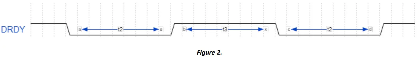
The following table shows the period of the pin for all sampling rates.
Table 3.
| () | (µ) | Description |
| 240 | 125 | 4 SPS |
| 55 | 20 SPS | |
| 19 | 50 SPS | |
| 9 | 100 SPS | |
| 4.5 | 200 SPS | |
| 1.5 | 500 SPS | |
| 1.1 | 850 SPS | |
| 0.6 | 1300 SPS |
“Stream” Mode
The Set System Stream State (SSSS) [with a payload of 1] command may be sent to activate the stream mode. The device will stop streaming as soon as the Set System Stream State command [with a payload of 0], or any other command is sent to QIA128.
*Note: There may be no response from the QIA128 if an incorrect command is sent.
UART Packet Structure
The packet structure and length for every command may vary due to their type (GET and SET) and functionalities; refer to the Command Set Table for further information.
System Behavior
Start-up and Self-Calibration Mode
When the system powers ON, it starts reading the data from EEPROM and goes to the internal calibration mode.
*Note: The first pulse could be used as an indicator for when the device is ready for communication.
Sampling Rate Change
When a sampling rate change is requested, it will take no more than 0.5 seconds (depending on the selected sampling rate) to see the change in the period.
Sampling Rates
Table 4.
| Maximum Approximate data rate change timing () | SR Code | Sampling Rate |
| ≅250 | 0x00 | 4 SPS |
| 0x01 | 20 SPS | |
| 0x02 | 50 SPS | |
| 0x03 | 100 SPS | |
| 0x04 | 200 SPS | |
| 0x05 | 500 SPS | |
| 0x06 | 850 SPS | |
| 0x07 | 1300 SPS |
Command-Set List
Table 6.
| Type | Name | Description | TX Packet Structure | RX Packet Structure | Bytes in Payload |
| Get | GSAI | Get slave activity inquiry (Used to test communication) | 00 05 00 01 0E | 00 05 00 01 0E | N/A |
| *Get | GCCR | Get channel current reading | 00 06 00 05 00 20 | See Payload Example | 4 |
| Set | SSSS | Set system stream state OFF | 00 06 00 0C 00 3C | 00 05 00 0C 3A | N/A |
| *Set | SSSS | Set system stream state ON | 00 06 00 0C 01 41 | 00 05 00 0C 3A … [Stream Bytes] | N/A … [4] |
| *Get | GDSN | Get the device serial number | 00 05 01 00 0D | See Payload Example | 4 |
| *Get | GDMN | Get device model number | 00 05 01 01 11 | See Payload Example | 10 |
| *Get | GDIN | Get device item number | 00 05 01 02 15 | See Payload Example | 10 |
| *Get | GDHV | Get device hardware version | 00 05 01 03 19 | See Payload Example | 1 |
| *Get | GDFV | Get device firmware version | 00 05 01 04 1D | See Payload Example | 3 |
| *Get | GDFD | Get device firmware date | 00 05 01 05 21 | See Payload Example | 3 |
| *Get | GPSSN | Get profile sensor serial number | 00 06 03 00 00 15 | See Payload Example | 4 |
| *Get | GPSPR | Get profile sampling rate | 00 06 03 1E 00 8D | See Payload Example | 1 |
| Set | SPSPR | Set profile sampling rate 4SPS | 00 07 04 1E 00 00 92 | 00 05 04 1E 8E | N/A |
| Set | SPSPR | Set profile sampling rate 20SPS | 00 07 04 1E 00 01 98 | 00 05 04 1E 8E | N/A |
| Set | SPSPR | Set profile sampling rate 50SPS | 00 07 04 1E 00 02 9E | 00 05 04 1E 8E | N/A |
| Set | SPSPR | Set profile sampling rate 100SPS | 00 07 04 1E 00 03 A4 | 00 05 04 1E 8E | N/A |
| Set | SPSPR | Set profile sampling rate 200SPS | 00 07 04 1E 00 04 AA | 00 05 04 1E 8E | N/A |
| Set | SPSPR | Set profile sampling rate 500SPS | 00 07 04 1E 00 05 B0 | 00 05 04 1E 8E | N/A |
| Set | SPSPR | Set profile sampling rate 850SPS | 00 07 04 1E 00 06 B6 | 00 05 04 1E 8E | N/A |
| Set | SPSPR | Set profile sampling rate 1300SPS | 00 07 04 1E 00 07 BC | 00 05 04 1E 8E | N/A |
| *Get | GPADP | Get profile analog-to-digital calibration value 0 (Direction 1) | 00 07 03 19 00 00 7B | See Payload Example | 4 |
| *Get | GPADP | Get profile analog-to-digital calibration value 1 (Direction 1) | 00 07 03 19 00 01 81 | See Payload Example | 4 |
| *Get | GPADP | Get profile analog-to-digital calibration value 2 (Direction 1) | 00 07 03 19 00 02 87 | See Payload Example | 4 |
| *Get | GPADP | Get profile analog-to-digital calibration value 3 (Direction 1) | 00 07 03 19 00 03 8D | See Payload Example | 4 |
| *Get | GPADP | Get profile analog-to-digital calibration value 4 (Direction 1) | 00 07 03 19 00 04 93 | See Payload Example | 4 |
QIA128 UART Communication Guide
| *Get | GPADP | Get profile analog-to-digital calibration value 5 (Direction 1) | 00 07 03 19 00 05 99 | See Payload Example | 4 |
| *Get | GPADP | Get profile analog-to-digital calibration value 6 (Direction 2) | 00 07 03 19 00 06 9F | See Payload Example | 4 |
| *Get | GPADP | Get profile analog-to-digital calibration value 7 (Direction 2) | 00 07 03 19 00 07 A5 | See Payload Example | 4 |
| *Get | GPADP | Get profile analog-to-digital calibration value 8 (Direction 2) | 00 07 03 19 00 08 AB | See Payload Example | 4 |
| *Get | GPADP | Get profile analog-to-digital calibration value 9 (Direction 2) | 00 07 03 19 00 09 B1 | See Payload Example | 4 |
| *Get | GPADP | Get profile analog-to-digital calibration value 10 (Direction 2) | 00 07 03 19 00 0A B7 | See Payload Example | 4 |
| *Get | GPADP | Get profile analog-to-digital calibration value 11 (Direction 2) | 00 07 03 19 00 0B BD | See Payload Example | 4 |
| *Get | GPADP | Get profile analog-to-digital calibration value 12 (Direction 1) | 00 07 03 19 00 0C C3 | See Payload Example | 4 |
| *Get | GPADP | Get profile analog-to-digital calibration value 13 (Direction 1) | 00 07 03 19 00 0D C9 | See Payload Example | 4 |
| *Get | GPADP | Get profile analog-to-digital calibration value 14 (Direction 1) | 00 07 03 19 00 0E CF | See Payload Example | 4 |
| *Get | GPADP | Get profile analog-to-digital calibration value 15 (Direction 1) | 00 07 03 19 00 0F D5 | See Payload Example | 4 |
| *Get | GPADP | Get profile analog-to-digital calibration value 16 (Direction 1) | 00 07 03 19 00 10 DB | See Payload Example | 4 |
| *Get | GPADP | Get profile analog-to-digital calibration value 17 (Direction 1) | 00 07 03 19 00 11 E1 | See Payload Example | 4 |
| *Get | GPADP | Get profile analog-to-digital calibration value 18 (Direction 2) | 00 07 03 19 00 12 E7 | See Payload Example | 4 |
| *Get | GPADP | Get profile analog-to-digital calibration value 19 (Direction 2) | 00 07 03 19 00 13 ED | See Payload Example | 4 |
| *Get | GPADP | Get profile analog-to-digital calibration value 20 (Direction 2) | 00 07 03 19 00 14 F3 | See Payload Example | 4 |
| *Get | GPADP | Get profile analog-to-digital calibration value 21 (Direction 2) | 00 07 03 19 00 15 F9 | See Payload Example | 4 |
| *Get | GPADP | Get profile analog-to-digital calibration value 22 (Direction 2) | 00 07 03 19 00 16 FF | See Payload Example | 4 |
*Note: The Payload bytes are located directly before the last byte of the packet which is the Checksum.
Payload Example
The following transaction is the response to the GDSN command (Get device serial number). This command has a payload of 4 bytes.
TX: 00 05 01 00 0D
RX: 00 09 01 00 00 01 E2 40 49
Hex to decimal: 0x0001E240 -> 123456
ADC Data Conversion
The following formula could be used to convert the raw ADC data: ![]()
Here are the variables:
ADCValue = the most recent analog-to-digital conversion value.
Off-set Value = the analog-to-digital conversion value stored during calibration that corresponds to the offset (zero physical loads).
Full-Scale Value = the analog-to-digital conversion value stored during calibration that corresponds to the full scale (maximum physical load).
Full-Scale Load = the numeric value stored during calibration for the maximum physical load.
ADC Data Conversion Examples (Direction 1, 2-point Calibration)
Calibration Data
Get profile analog-to-digital calibration value 0 (Direction 1) [GPADP]:
Hex to decimal: 0x81B320 -> 000,500,8
Get profile analog-to-digital calibration value 5 (Direction 1) [GPADP]:
Hex to decimal: 0xB71B00 -> 12,000,000
Get channel current reading (GCCR):
Hex to decimal: 0x989680 -> 10,0000,00
Calculation
OffsetValue = 8,500,000
FullScaleValue = 12,000,000
FullScaleLoad = 20g (Available on the calibration certificate)![]()
Firmware Revision
![]()
Firmware Notes
New Features
• N/A
Changes
• N/A
Fixes
• Changed the hardware revision from “0” to “1”.
![]() Sensor Solution Source
Sensor Solution Source
Load • Torque • Pressure • Multi-Axis • Calibration Instruments • Software
10 Thomas, Irvine, CA 92618 USA
Tel: (949) 465-0900
Fax: (949) 465-0905
www.futek.com


