iSMACONTROLLI SfAR-S-8AO 8 Analog Outputs Expansion Module
Introduction
Thank you for choosing our product. This manual will help you with proper handling and operating of the device. The information included in this manual have been prepared with utmost care by our professionals and serve as a description of the product without incurring any liability for the purposes of commercial law. This information does not discharge you from the liability of your own judgement and verification. We reserve the right to change product specifications without notice. Please read the instructions carefully and follow the recommendations concluded therein.
WARNING! Failure to follow instructions can result in equipment damage or impede the use of the hardware or software.
Revision History
| Rev. | Date | Description |
| 3.2 | 25 May 2022 | Rebranded |
Safety Rules
- Improper wiring of the product can damage it and lead to other hazards. Make sure that the product has been correctly wired before turning the power on.
- Before wiring or removing/mounting the product, make sure to turn the power off.
- Failure to do so might cause an electric shock.
- Do not touch electrically charged parts such as power terminals. Doing so might cause an electric shock.
- Do not disassemble the product. Doing so might cause an electric shock or faulty operation.
- Use the product only within the operating ranges recommended in the specification (temperature, humidity, voltage, shock, mounting direction, atmosphere, etc.). Failure to do so might cause a fire or faulty operation.
- Firmly tighten the wires to the terminal. Failure to do so might cause a fire.
- Avoid installing the product in close proximity to high-power electrical devices and cables, inductive loads, and switching devices. Proximity of such objects may cause an uncontrolled interference, resulting in an instable operation of the product.
- Proper arrangement of the power and signal cabling affects the operation of the entire control system. Avoid laying the power and signal wiring in parallel cable trays. It can cause interferences in monitored and control signals.
- It is recommended to power controllers/modules with AC/DC power suppliers. They provide better and more stable insulation for devices compared to AC/AC transformer systems, which transmit disturbances and transient phenomena like surges and bursts to devices. They also isolate products from inductive phenomena from other transformers and loads.
- Power supply systems for the product should be protected by external devices limiting overvoltage and effects of lightning discharges.
- Avoid powering the product and its controlled/monitored devices, especially high power and inductive loads, from a single power source. Powering devices from a single power source causes a risk of introducing disturbances from the loads to the control devices.
- If an AC/AC transformer is used to supply control devices, it is strongly recommended to use a maximum 100 VA Class 2 transformer to avoid unwanted inductive effects, which are dangerous for devices.
- Long monitoring and control lines may cause loops in connection with the shared power supply, causing disturbances in the operation of devices, including external communication. It is recommended to use galvanic separators.
- To protect signal and communication lines against external electromagnetic interferences, use properly grounded shielded cables and ferrite beads.
- Switching the digital output relays of large (exceeding specification) inductive loads can cause interference pulses to the electronics installed inside the product. Therefore, it is recommended to use external relays/contactors, etc. to switch such loads. The use of controllers with triac outputs also limits similar overvoltage phenomena.
- Many cases of disturbances and overvoltage in control systems are generated by switched, inductive loads supplied by alternating mains voltage (AC 120/230 V). If they do not have appropriate built-in noise reduction circuits, it is recommended to use external circuits such as snubbers, varistors, or protection diodes to limit these effects.
Module Features
Purpose and Description of the Module
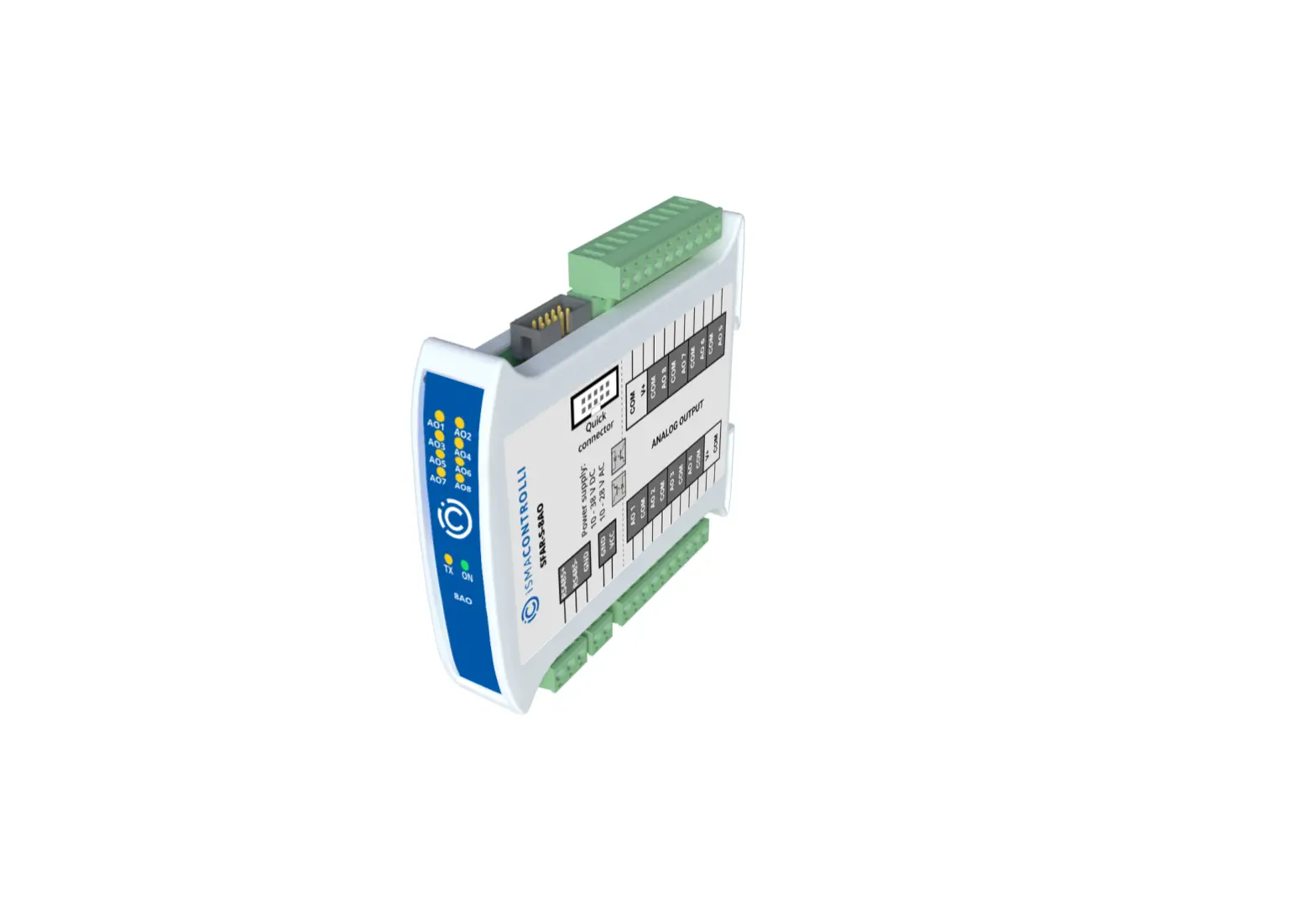
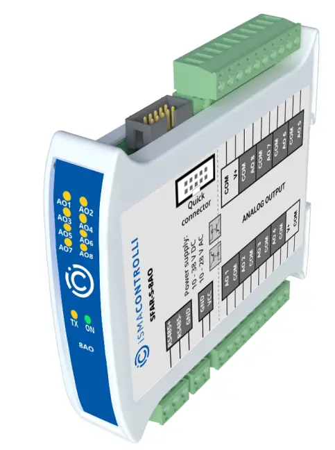
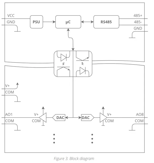
The SfAR-S-8AO module has a set of 8 analog outputs that can work as current outputs (0-20 mA or 4-20 mA) or as voltage outputs (0-10 V). Setting the output current or voltage mode is done via RS485 (Modbus protocol), so the module can be easily integrated with popular PLCs, HMI, or PC equipped with the appropriate adapter. The module is connected to the RS485 bus with a twisted-pair wire. Communication is via Modbus RTU or Modbus ASCII. The use of 32-bit ARM core processor provides fast processing and quick communication. The baud rate is configurable from 2400 to 115200. The module is designed for mounting on a DIN rail in accordance with DIN EN 5002. The module is equipped with a set of LEDs to indicate the status of inputs and outputs which is useful for diagnostic purposes and helping to find errors. Module configuration is done via USB by using a dedicated computer program. It also allows for changing the parameters using the Modbus protocol or set the Modbus address using the DIP switches under the front panel.
Technical Specification
| Power Supply | Voltage | 10-38 V DC; 10-28 V AC |
| Power consumption (with active Modbus transmission, all outputs on) | 1.25 W at 24 V DC | |
| 1.5 VA at 24 V AC | ||
| Isolation | Isolation between power supply and I/O | 1000 V DC |
| Outputs | No. of outputs | 8 |
| Voltage output | 0 V do 10 V (resolution 1.5 mV) | |
| Max. load current 0-10 V 5 mA | ||
| Accuracy ±2% | ||
| Current output | 0 mA – 20 mA (resolution 5 μA) | |
| 4 mA – 20 mA (value in ‰ – 1000 steps) (resolution 16 μA) | ||
| Max. resistance 500 ohm | ||
| Accuracy ±1% | ||
| Output resolution | 12-bit | |
| DAC processing time | 16 ms/channel |
| Temperature | Work | -10°C to +50°C (14°F to 122°F) |
| Storage | -40°C to +85°C (-40°F to 185°F) | |
| Connectors | Power supply | 2 pins |
| Communication | 3 pins | |
| Outputs | 2 x 10 pins | |
| Quick connector | IDC10 | |
| Configuration | mini USB | |
| Size | Height | 119.1 mm (4.689 in) |
| Length | 110.9 mm (4.366 in) | |
| Width | 22.7 mm (0.894 in) | |
| Interface | RS485 | Up to 128 devices |
Dimensions
The appearance and dimensions of the module are shown below. The module is mounted directly to the rail in the DIN industry standard. Power connectors, communication and IOs are at the bottom and top of the module. USB connector configuration and indicators located on the front of the module.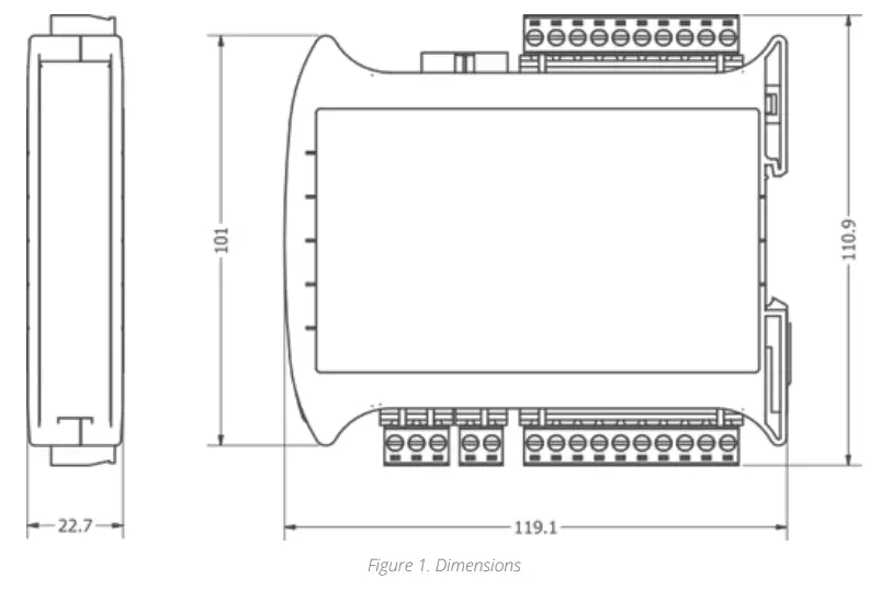
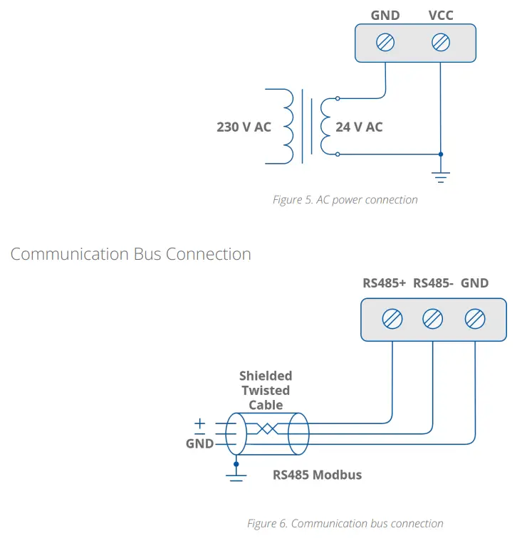
Communication
Grounding and Shielding
In most cases, I/O modules will be installed in an enclosure along with the other devices, which generate electromagnetic radiation. Relays, contactors, transformers, motor invertors, etc., are examples of such devices. Radiation can induce electrical noise into both power and signal lines, as well as direct radiation into the module. Whether or not the SfAR modules are immune to such effects, the interferences must be suppressed at their source if possible to ensure the proper functioning of the entire system. Appropriate grounding, shielding and other protective steps should be taken at the installation stage to prevent these effects. It is recommended to at least follow the rules below:
- line power cables must be routed with spatial separation from signal and data transmission cables;
- analog and digital signal cables should also be separated;
- it is recommended to use shielded cables for analog signals, cable shields should not be interrupted by intermediate terminals;
- the shielding should be earthed directly after the cable enters the cabinet.
It is recommended to install interference suppressors when switching inductive loads (e.g., coils of contactors, relays, solenoid valves). RC snubbers or varistors are suitable for AC voltage and freewheeling diodes for DC voltage loads. The suppressing elements must be connected as close to the coil as possible.
Network Termination
Transmission line effects often present problems for data communication networks. These problems include reflections and signal attenuation. To eliminate the presence of reflections of signal from the end of the cable, the cable must be terminated at both ends with a resistor across the line adequate to its characteristic impedance. Both ends must be terminated since the propagation is bidirectional. In case of an RS485 twisted paircable, this termination is typically 120 Ω.
Setting Module Address in RS485 Modbus Network
The following table shows how to set switch to determine the address of the module. The module address is set with the switches in the range of 0 to 31. Addresses from 32 to 255 can be set via RS485 or USB.
| Addr | SW1 | SW2 | SW3 | SW4 | SW5 |
| 0 | OFF | OFF | OFF | OFF | OFF |
| 1 | ON | OFF | OFF | OFF | OFF |
| 2 | OFF | ON | OFF | OFF | OFF |
| 3 | ON | ON | OFF | OFF | OFF |
| 4 | OFF | OFF | ON | OFF | OFF |
| Addr | SW1 | SW2 | SW3 | SW4 | SW5 |
| 5 | ON | OFF | ON | OFF | OFF |
| 6 | OFF | ON | ON | OFF | OFF |
| 7 | ON | ON | ON | OFF | OFF |
| 8 | OFF | OFF | OFF | ON | OFF |
| 9 | ON | OFF | OFF | ON | OFF |
| 10 | OFF | ON | OFF | ON | OFF |
| 11 | ON | ON | OFF | ON | OFF |
| 12 | OFF | OFF | ON | ON | OFF |
| 13 | ON | OFF | ON | ON | OFF |
| 14 | OFF | ON | ON | ON | OFF |
| 15 | ON | ON | ON | ON | OFF |
| 16 | OFF | OFF | OFF | OFF | ON |
| 17 | ON | OFF | OFF | OFF | ON |
| 18 | OFF | ON | OFF | OFF | ON |
| 19 | ON | ON | OFF | OFF | ON |
| 20 | OFF | OFF | ON | OFF | ON |
| 21 | ON | OFF | ON | OFF | ON |
| 22 | OFF | ON | ON | OFF | ON |
| 23 | ON | ON | ON | OFF | ON |
| 24 | OFF | OFF | OFF | ON | ON |
| 25 | ON | OFF | OFF | ON | ON |
| 26 | OFF | ON | OFF | ON | ON |
| 27 | ON | ON | OFF | ON | ON |
| 28 | OFF | OFF | ON | ON | ON |
| 29 | ON | OFF | ON | ON | ON |
| 30 | OFF | ON | ON | ON | ON |
| Addr | SW1 | SW2 | SW3 | SW4 | SW5 |
| 31 | ON | ON | ON | ON | ON |
Types of Modbus Functions
There are 4 types of Modbus functions supported by the SfAR modules.
| Type | Beginning Address | Variable | Access | Modbus Command |
| 1 | 00001 | Digital Outputs | Bit Read/write | 1, 5, 15 |
| 2 | 10001 | Digital Inputs | Bit Read | 2 |
| 3 | 30001 | Input Registers | Registered Read | 3 |
| 4 | 40001 | Output Registers | Registered Read/write | 4, 6, 16 |
Communication Settings
The data stored in the module’s memory is given in the 16-bit registers. The access to registers is via Modbus RTU or Modbus ASCII.
Default Settings
The default configuration can be restored with the DIP switch, SW6.
| Baud Rate | 19200 |
| Parity | No |
| Data Bits | 8 |
| Stop Bits | 1 |
| Reply Delay [ms] | 0 |
| Modbus Type | RTU |
Restoring Default Configuration
To restore the default configuration, follow the steps below:
- turn the power off;
- turn the switch SW6 on;
- turn the power on;
- when power and communication LED is lit, turn the switch SW6 off.
WARNING! After restoring the default configuration, all values stored in the registers will be cleared as well.
Configuration Registers
| Modbus Address | Decimal Address | Hex Address | Name | Values |
| 40003 | 2 | 0x02 | Baud Rate | 0 – 2400 1 – 4800 2 – 9600 3 – 19200 4 – 38400 5 – 57600 6 – 115200 other – value * 10 |
| 40005 | 4 | 0x04 | Parity | 0 – none 1 – odd 2 – even 3 – always 0 4 – always 1 |
| 40004 | 3 | 0x03 | Stop Bits | 1 – one stop bit 2 – two stop bits |
| 40004 | 3 | 0x03 | Data Bits | 7 – 7 data bits 8 – 8 data bits |
| 40006 | 5 | 0x05 | Response Delay | Time in ms |
| 40007 | 6 | 0x06 | Modbus Mode | 0 – RTU 1 – ASCII |
Watchdog
This 16-bits register specifies the time in milliseconds to watchdog reset. If module does not receive any valid message within that time, all Digital and Analog Outputs will be set to the default state. This feature is useful if there is an interruption in data transmission and for security reasons. Output states must be set to the appropriate state in order to reassure the safety of persons or property. The default value is 0 milliseconds which means the watchdog function is disabled.
Indicators
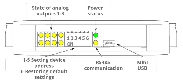
| Indicator | Description |
| Power Supply | The LED indicates that the module is correctly powered |
| Communication | The LED lights up when the unit received the correct packet and sends the answer |
| Outputs State | The LED indicates that the output is on |
Connections
Block Diagram
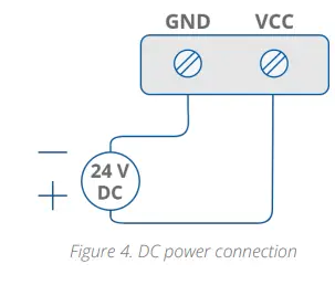
Power Supply Connection
- DC Power Connection:

- AC Power Connection:

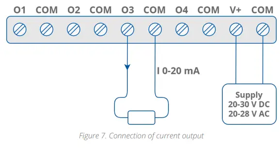
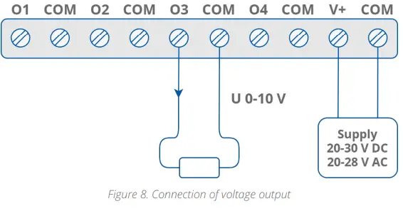
Connection of Analog Outputs
- Connection of Current Output:

- Connection of Voltage Output:

Quick Connector
The Quick Connector is a unique feature of modules that allows for quickly connecting a group of devices with a flat ribbon cable. Thanks to this solution, it is enough to connect power an RS485 communication to one of the devices in the group, and the others will be powered and communicated with ribbon cable. The Quick Connector is sufficient to connect up to 10 devices next to each other. It is important that the various types of modules in the SfAR-S family can be connected with the ribbon cable.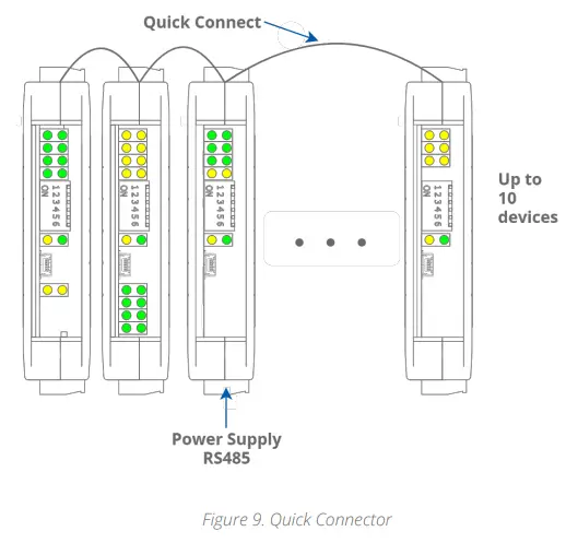
Setting Output Mode
To change the output mode from current to voltage, it is required to set appropriate values of Modbus registers (40069-40076) and change the position of a jumper inside the module, according to the following picture.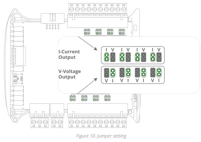
Opening the Case

- Remove the catch by pressing it and moving it towards the center of the case. Mind the spring located under the catch.
- Separate parts of the case by gently tilting catches located as shown in the picture using a thin tool.
DIP Switch
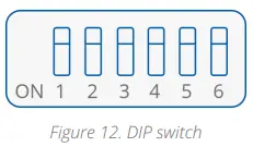
| Switch | Function | Description |
| 1 | Module address +1 | Setting module address from 0 to 31 |
| 2 | Module address +2 | |
| 3 | Module address +4 | |
| 4 | Module address +8 | |
| 5 | Module address +16 | |
| 6 | Restoring default settings | Restoring default settings |
Module Registers
Registered Access
| Modbus | Dec | Hex | Register Name | Access | Description |
| 30001 | 0 | 0x00 | Version/Type | Read | Version and type of the device |
| 30002 | 1 | 0x01 | Switches | Read | Switches state |
| 40003 | 2 | 0x02 | Baud Rate | Read/write | RS485 baud rate |
| 40004 | 3 | 0x03 | Stop Bits & Data Bits | Read/write | No. of stop bits & data bits |
| 40005 | 4 | 0x04 | Parity | Read/write | Parity bit |
| 40006 | 5 | 0x05 | Response Delay | Read/write | Response delay in ms |
| 40007 | 6 | 0x06 | Modbus Mode | Read/write | Modbus Mode (ASCII or RTU) |
| 40009 | 8 | 0x08 | Watchdog | Read/write | Watchdog |
| 40033 | 32 | 0x20 | Received Packets LSR (Least Significant Register) | Read/write | No. of received packets |
| 40034 | 33 | 0x21 | Received Packets MSR (Most Significant Register) | Read/write | |
| 40035 | 34 | 0x22 | Incorrect Packets LSR | Read/write | No. of received packets with error |
| 40036 | 35 | 0x23 | Incorrect Packets MSR | Read/write | |
| 40037 | 36 | 0x24 | Sent Packets LSR | Read/write | No. of sent packets |
| 40038 | 37 | 0x25 | Sent Packets MSR | Read/write | |
| 30051 | 50 | 0x32 | Outputs | Read | Bit is set if value ≠ 0 |
| 40053 | 52 | 0x34 | Analog output 1 | Read/write | Value of Analog Output: in mV for voltage output (max 10240)
in μA for current output 0 – 20 mA (max 20480) in ‰ for current output 4-20 mA (max 1000) |
| 40054 | 53 | 0x35 | Analog Output 2 | Read/write | |
| 40055 | 54 | 0x36 | Analog Output 3 | Read/write | |
| 40056 | 55 | 0x37 | Analog Output 4 | Read/write | |
| 40057 | 56 | 0x38 | Analog Output 5 | Read/write | |
| 40058 | 57 | 0x39 | Analog Output 6 | Read/write | |
| 40059 | 58 | 0x3A | Analog Output 7 | Read/write | |
| 40060 | 59 | 0x3B | Analog Output 8 | Read/write |
| Modbus | Dec | Hex | Register Name | Access | Description |
| 40061 | 60 | 0x3C | Default Output 1 Value | Read/write | Default value of output set when power is on or when watchdog reset occurs |
| 40062 | 61 | 0x3D | Default Output 2 Value | Read/write | |
| 40063 | 62 | 0x3E | Default Output 3 Value | Read/write | |
| 40064 | 63 | 0x3F | Default Output 4 Value | Read/write | |
| 40065 | 64 | 0x40 | Default Output 5 Value | Read/write | |
| 40066 | 65 | 0x41 | Default Output 6 Value | Read/write | |
| 40067 | 66 | 0x42 | Default Output 7 Value | Read/write | |
| 40068 | 67 | 0x43 | Default Output 8 Value | Read/write | |
| 40069 | 68 | 0x44 | Output 1 Setting | Read/write | Setting of output mode: 0 – output disabled 1 – voltage output 2 – current output 0-20 mA 3 – current output 4-20 mA Caution! For the change to take effect, you must also set the jumper inside the module. |
| 40070 | 69 | 0x45 | Output 2 Setting | Read/write | |
| 40071 | 70 | 0x46 | Output 3 Setting | Read/write | |
| 40072 | 71 | 0x47 | Output 4 Setting | Read/write | |
| 40073 | 72 | 0x48 | Output 5 Setting | Read/write | |
| 40074 | 73 | 0x49 | Output 6 Setting | Read/write | |
| 40075 | 74 | 0x4A | Output 7 Setting | Read/write | |
| 40076 | 75 | 0x4B | Output 8 Setting | Read/write |
Bit Access
| Modbus Address | Dec Address | Hex Address | Register Name | Access | Description |
| 801 | 800 | 0x320 | Output 1 | Read | If voltage or current is greater than 0 then according bit is set. |
| 802 | 801 | 0x321 | Output 2 | Read | |
| 803 | 802 | 0x322 | Output 3 | Read | |
| 804 | 803 | 0x323 | Output 4 | Read | |
| 805 | 804 | 0x324 | Output 5 | Read | |
| 806 | 805 | 0x325 | Output 6 | Read | |
| 807 | 806 | 0x326 | Output 7 | Read | |
| 808 | 807 | 0x327 | Output 8 | Read |
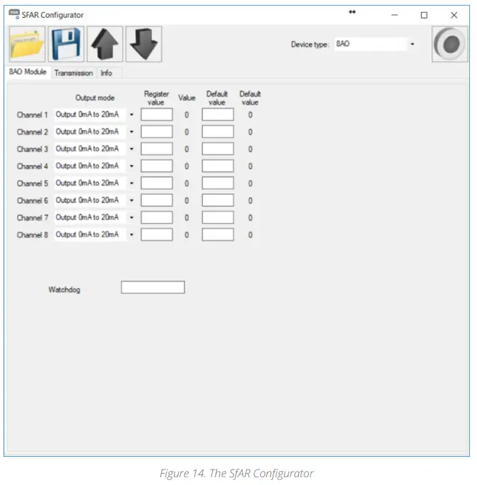
Configuration Software
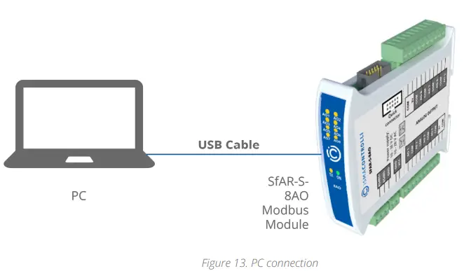
The SfAR Configurator is the type of software, which is designed to set the communication module registers over Modbus network as well as to read and write the current value of other registers of the module. It is a convenient way to test the system as well as to observe real-time changes in the registers. Communication with the module is via the USB cable. The module does not require any drivers.
The SfAR Configurator is a universal software, where it is possible to configure all available modules.
DMP274en | 3rd Issue rev. 2 | 05/2022


