
Circutor CEM M-ETH Communication Module for CEM Meters
SAFETY PRECAUTIONS
Follow the warnings described in this manual with the symbols shown below.
DANGER
Warns of a risk, which could result in personal injury or material damage.
ATTENTION
Indicates that special attention should be paid to a specific point.
If you must handle the unit for its installation, start-up or maintenance, the following should be taken into consideration:
Incorrect handling or installation of the unit may result in injury to personnel as well as damage to the unit. In particular, handling with voltages applied may result in electric shock, which may cause death or serious injury to personnel. Defective installation or maintenance may also lead to the risk of fire. Read the manual carefully prior to connecting the unit. Follow all installation and maintenance in-structions throughout the unit’s working life. Pay special attention to the installation standards of the National Electrical Code.
Refer to the instruction manual before using the unit
In this manual, if the instructions marked with this symbol are not respected or carried out correctly, it can result in injury or damage to the unit and /or installations.
DISCLAIMER
CIRCUTOR SA reserves the right to make modifications to the device or the unit specifications set out in this instruction manual without prior notice.
CIRCUTOR SA on its web site, supplies its customers with the latest versions of the device specifica-tions and the most updated manuals.
CIRCUTOR, recommends using the original cables and accessories that are supplied with the device.
| Date | Revision | Description |
| 11/14 | M060B01-03-14A | Initial Version |
| 04/21 | M060B01-03-21A | Circutor logo change |
- VERIFICATION UPON RECEPTION
Check the following points upon receiving the unit:
a) The unit meets the specifications described in your order.
b) The unit has not suffered any damage during transport.
c) Perform an external visual inspection of the unit prior to switching it on.
d) Check that it has been delivered with the following:
– An installation guide,.
If any problem is noticed upon reception, immediately contact the transport com-pany and/or CIRCUTOR’s after-sales service. PRODUCT DESCRIPTION
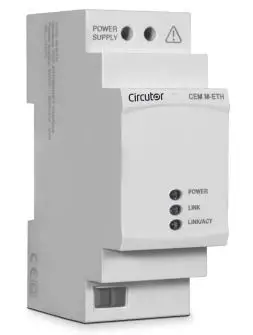
The CEM M-ETH optical-electric interface converts the optical service port of any unit of the CEM range into an Ethernet port with MODBUS/TCP protocol.

The unit features:
– 3 indicator LEDs: POWER, LINK and LINK/ACT.
The unit is installed on 2-step DIN rails, on the left of any unit of the CEM range.
UNIT INSTALLATION
PRELIMINARY RECOMMENDATIONS
In order to use the unit safely, it is critical that the individuals who handle it follow the safety measures set out in the standards of the country where it is being used, use the necessary personal protective equipment and pay attention to the various warnings indicated in this instruction manual.
The CEM M-ETH unit must be installed by authorised and qualified staff.
The power supply plug must be disconnected before handling, altering the connections or replacing the unit. It is dangerous to handle the unit while it is powered.
Also, it is critical to keep the cables in perfect condition in order to avoid accidents, personal injury and damage to installations.
The manufacturer of the unit is not responsible for any damage resulting from failure by the user or installer to observe the warnings and/or recommendations set out in this manual, nor for damage resulting from the use of non-original products or accessories or those made by other manufacturers.
If an anomaly or malfunction is detected in the unit, do not use the unit to take any measurements.
Inspect the work area before taking any measurements. Do not take measurements in dangerous ar-eas or where there is a risk of explosion.
Disconnect the unit from the power supply (unit and measuring system power supply) before maintaining, repairing or handling the unit’s connections.
Please contact the after-sales service if you suspect that there is an operational fault in the unit.
INSTALLATION
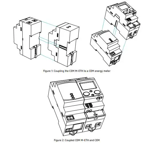
On the side of the unit are all of the indications adjusted to the CEI 62052-11 standard. The unit is installed on a DIN rail. Before connecting the unit, you must couple it to a CEM energy meter as shown in Figure 1 and Figure 2.
Terminals, opening covers or removing elements can expose parts that are hazardous to the touch while the unit is powered. Do not use the unit until it is fully installed.
The unit must be connected to a power circuit that is protected with gL fuses (IEC 269) or M fuses, with a rating of 0.5 to 2 A. It must be fitted with a circuit breaker switch or equivalent device for disconnect-ing the unit from the power supply mains.
The RCCB or equivalent device must be in the immediate vicinity of the unit and must be easily acces-sible.
The power circuit is connected with a cable with a section measuring up to 2.5 mm2.
The unit’s operating temperature is between -25ºC and +70ºC; always use connection cables that can withstand these temperatures.
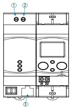
UNIT TERMINALS
Table 2:List of CEM M-ETH terminals
| Unit terminals |
| 1: Auxiliary power supply. |
| 2: Auxiliary power supply. |
| 3: Ethernet. |
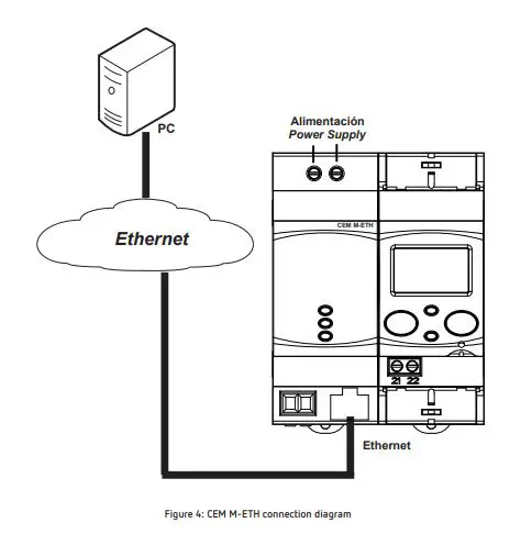
CONNECTION DIAGRAM
The connection between the CEM M-ETH and the Ethernet network must be made with a twisted pair cable (100Base-TX: 100Mbit/s on two pairs of wires of Category 5 or higher). The segment length of the 100Base-T, 10BaseT and 1000Base-T cables is limited to 100 m.
OPERATION
The CEM M-ETH is designed to be used as a Ethernet port for any device in the CEM family, using the mechanical coupling next to the optical port.
OPERATING PRINCIPLE
The CEM M-ETH is an optional accessory for electrical energy meters from the CEM range that are mounted on DIN rails.
The CEM M-ETH provides CEM units with Ethernet communications with the MODBUS/TCP protocol.
Once the unit is coupled to the CEM energy meter (See “3.2.- INSTALLATION”) the LINK LED turns green to let the user know that the link has been made correctly.
From this point onward, the new CEM energy meter + CEM M-ETH assembly functions as a single device.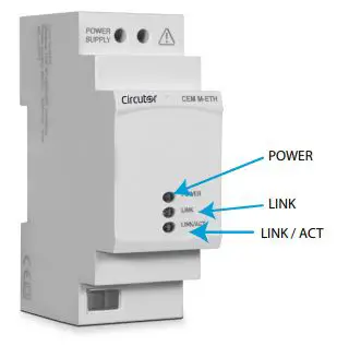
- POWER LED: Indicates that the unit is connected to a power supply.
- LINK LED: Indicates the status of the link with the CEM unit. (Table 3)
Table 3:LINK LED, colour codes
| LINK LED | |
| Colour | Status |
| Flashing red | Unit not linked |
| Steady green | Unit linked |
LED LINK/ACT, indicates the state of the Ethernet connection, Table 4.
Table 4: LED LINK/ACT
| LED LINK/ ACT | |
| Colour | Status |
| On | Ethernet link |
| Off | No Ethernet link |
| Flashing | Activity on this port |
OPTICAL COMMUNICATIONS PORT
The unit has an optical serial communications port on its right side, in accordance with the UNE EN 62056-21:2003 standard, in order to communicate with other devices in the CEM family.
RS-485 COMMUNICATIONS
The MODBUS/TPC protocol is the MODBUS RTU protocol with a TCP interface that runs on Ethernet.
MODBUS/TCP uses TCP/IP and Ethernet to manage the data of MODBUS messages between compatible devices.
The MODBUS/TCP protocol embeds a standard MODBUS data frame in a TCP frame without the Modbus checksum, as shown in the diagram in the figure.
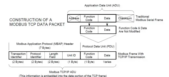
Table 5 shows the format of the MODBUS/TCP frame.
Table 5: MODBUS/TCP frame format
| Name | Length | Function |
| Transaction identifier | 2 | For message synchronisation between the server and client. |
| Protocol identifier | 2 | Value 0 for MODBUS/TCP |
| Field length | 2 | Number of bytes remaining in the frame |
| Unit identifier | 1 | Peripheral number |
| Function code | 1 | Modbus function number |
| Data bytes | n | Response or command data |
The MODBUS functions implemented in the unit are:
Functions 03 and 04. Reading of logs. Function 10. Writing of multiple logs.
VARIABLES MODBUS
All MODBUS map addresses are hexadecimal.
Configuration variables
The Read and Write functions are implemented for these variables.
Table 6:Modbus configuration variables CEM M-RS485.
| Description | Address | Size | Valid data range | Default value |
| Impulse output type | 0x0080 | 16 bits | 0: Active energy, 1: Reactive energy | 0 |
| Impulse output weight | 0x0081 | 16 bits | Wh/impulse 0 … 99999 | – |
| Cost per kWh | 0x00B0 | 32 bits | 0.0000…. 9999.9999 with 4 decimal places of resolution | – |
| KgCO2 | 0x00B2 | 32 bits | 0.0000…. 9.0000 with 4 decimal places of resolution | – |
Note: Some MODBUS variables may not be available depending on the CEM energy meter coupled to the CEM M-ETH. See “4.4.2.7.- Available addresses by unit”
Energy
The Read function is implemented for these variables.
| Description | Address | Size | Units |
| Total values | |||
| Imported active energy | 0x0000 | 32 bits | Wh |
| Exported active energy | 0x0002 | 32 bits | Wh |
| Q1 reactive energy | 0x0004 | 32 bits | varh |
| Q2 reactive energy | 0x0006 | 32 bits | varh |
| Q3 reactive energy | 0x0008 | 32 bits | varh |
| Q4 reactive energy | 0x000A | 32 bits | varh |
| Partial values | |||
| Partial imported active energy | 0x0030 | 32 bits | Wh |
| Partial exported active energy | 0x0032 | 32 bits | Wh |
| Q1 partial reactive energy | 0x0034 | 32 bits | varh |
| Q2 partial reactive energy | 0x0036 | 32 bits | varh |
| Q3 partial reactive energy | 0x0038 | 32 bits | varh |
| Q4 partial reactive energy | 0x003A | 32 bits | varh |
Note: Some MODBUS variables may not be available depending on the CEM energy meter coupled to the CEM M-ETH. See “4.4.2.7.- Available addresses by unit”
Operating time, cost and KgCO2 atmospheric emissions
The Read function is implemented for these variables.
Table 8: Modbus variables: Operating time, costs and KgCO2
| Description | Address | Size | Units |
| Cost of the partial consumption | 0x00C0 | 32 bits | – |
| KgCO2 atmospheric emissions of the partial consumption | 0x00C2 | 32 bits | – |
| Hours of partial operation | 0x00C4 | 32 bits | ( 1 decimal place) |
| Hours of total operation | 0x00C6 | 32 bits | ( 1 decimal place) |
Note: Some MODBUS variables may not be available depending on the CEM energy meter coupled to the CEM M-ETH. See “4.4.2.7.- Available addresses by unit”
Instantaneous values
The Read function is implemented for these variables.
Table 9: Modbus variables: Instantaneous values.
| Description | Address | Size | Units |
| Phase 1 voltage | 0x0732 | 32 bits | V (1 primary decimal place) |
| Phase 2 voltage | 0x0734 | 32 bits | V (1 primary decimal place) |
| Phase 3 voltage | 0x0736 | 32 bits | V (1 primary decimal place) |
| Phase 1 current | 0x0738 | 32 bits | A (2 primary decimal places) |
| Phase 2 current | 0x073A | 32 bits | A (2 primary decimal places) |
| Phase 3 current | 0x073C | 32 bits | A (2 primary decimal places) |
| Phase 1 cos φ | 0x073E | 32 bits | 2 decimal places |
Table 9 (Continuation): Modbus variables: Instantaneous values
| Description | Address | Size | Units |
| Phase 2 cos φ | 0x0740 | 32 bits | 2 decimal places |
| Phase 3 cos φ | 0x0742 | 32 bits | 2 decimal places |
| Phase 1 active power | 0x0746 | 32 bits | W |
| Phase 2 active power | 0x0748 | 32 bits | W |
| Phase 3 active power | 0x074A | 32 bits | W |
| Total active power | 0x074C | 32 bits | W |
| Phase 1 reactive power | 0x074E | 32 bits | var |
| Phase 2 reactive power | 0x0750 | 32 bits | var |
| Phase 3 reactive power | 0x0752 | 32 bits | var |
| Total reactive power | 0x0754 | 32 bits | var |
| Phase 1 apparent power | 0x0756 | 32 bits | VA |
| Phase 2 apparent power | 0x0758 | 32 bits | VA |
| Phase 3 apparent power | 0x075A | 32 bits | VA |
| Total apparent power | 0x075C | 32 bits | VA |
Note: Some MODBUS variables may not be available depending on the CEM energy meter coupled to the CEM M-ETH. See “4.4.2.7.- Available addresses by unit”
Other parameters
The Read function is implemented for these variables.
Table 10: Modbus variables: Other parameters.
| Description | Address | Size | Units |
| Energy meter model1) | 0xF010 | 6×16 bits | 12 bytes in ASCII format |
| Serial no | 0x2710 | 32 bits | – |
| Transformation ratios | |||
| Voltage primary | 0x044C | 32 bits | V (1 decimal place) |
| Voltage secondary | 0x044E | 32 bits | V (1 decimal place) |
| Current primary | 0x0450 | 32 bits | A (1 decimal place) |
| Current secondary | 0x0452 | 32 bits | A (1 decimal place) |
| Energy meter firmware version | |||
| Higher firmware version | 0x0050 | 16 bits | – |
| Lower firmware version | 0x0051 | 16 bits | – |
| Revised firmware version | 0x0052 | 16 bits | – |
| Communications module firmware version | |||
| Higher firmware version | 0x0578 | 16 bits | – |
| Lower firmware version | 0x0579 | 16 bits | – |
| Revised firmware version | 0x057A | 16 bits | – |
Note: Some MODBUS variables may not be available depending on the CEM energy meter coupled to the CEM M-ETH. See “4.4.2.7.- Available addresses by unit”
(1) Energy meter model description table, Table 11.
| Options | C10 | C20 | C30 | bytes in ASCII format | |
| Connection mode | 2 wires | ü | 2 | ||
| 4 wires | ü | ü | 4 | ||
| Accuracy | Class B active / Does not measure reactive energy | ü | ü | ü | 10 |
| Class B active / Class 2.0 reactive | ü | ü | ü | 12 | |
|
Measurement voltage | 1×230 | ü | E | ||
| 1×127 | ü | B | |||
| 3×127/220 … 3×230/400 V | ü | U | |||
| 3×127/220 V | ü | ü | N | ||
| 3×230/400 V | ü | ü | Q | ||
| 3×57/100 … 3×230/400 V | ü | V | |||
| 3×57/100 V | ü | L | |||
| 3×63.5/110 V | ü | M | |||
|
Current measurement | Shunt 10(60) A | ü | S4 | ||
| Shunt 5(65) A | ü | S7 | |||
| Direct 10(60)A | ü | D4 | |||
| Direct 5(65)A | ü | D7 | |||
| Transformer 5(10) A | ü | T5 | |||
| Transformer 5(6) A | ü | T6 | |||
| Frequency | 50Hz | ü | ü | ü | A |
| 60 Hz | ü | ü | ü | B | |
| Automatic (50/60Hz) | ü | ü | ü | C | |
| Communications | Without communications | ü | ü | ü | 0 |
| Side optical service port | ü | ü | ü | 1 | |
| Expansion | Without inputs/outputs | ü | ü | ü | 0 |
| Input/Output (Optocoupler) | ü | ü | ü | 1 | |
| Model | Box for assembly on DIN rail | ü | ü | ü | E |
| Number of quadrants | 2 quadrants | ü | ü | ü | 0 |
| 4 quadrants | ü | ü | ü | 1 | |
| Storage in both directions | ü | ü | ü | 2 | |
| Additional features | No special features | ü | ü | ü | 0 |
Partial energy reset
The 0x05 function is implemented for this variable.
| Description | Address | Activation |
| Partial energy reset | 0x0800 | 0xFF00 |
Table 13: Modbus variables: Available addresses by unit.
| Address | C10 | C20 | C30 | Description |
| 0x03E8 | ü | ü | ü | Modbus Address |
| 0x03E9 | ü | ü | ü | Transmission speed |
| 0x03EA | ü | ü | ü | Communications configuration |
| 0x0080 | ü | ü | ü | Impulse output type |
| 0x0081 | ü | ü | ü | Impulse output weight |
| 0x00B0 | ü | ü | ü | Cost per kWh |
| 0x00B2 | ü | ü | ü | KgCO2 |
| 0x0000 | ü | ü | ü | Imported active energy |
| 0x0002 | ü | ü | ü | Exported active energy |
| 0x0004 | ü | ü | ü | Q1 reactive energy |
| 0x0006 | ü | ü | ü | Q2 reactive energy |
| 0x0008 | ü | ü | ü | Q3 reactive energy |
| 0x000A | ü | ü | ü | Q4 Reactive energy |
| 0x0030 | ü | ü | ü | Partial imported active energy |
| 0x0032 | ü | ü | ü | Partial exported active energy |
| 0x0034 | ü | ü | ü | Q1 partial reactive energy |
| 0x0036 | ü | ü | ü | Q2 partial reactive energy |
| 0x0038 | ü | ü | ü | Q3 partial reactive energy |
| 0x003A | ü | ü | ü | Q4 partial reactive energy |
| 0x00C0 | ü | ü | ü | Cost of the partial consumption |
| 0x00C2 | ü | ü | ü | KgCO2 atmospheric emissions of the partial consumption |
| 0x00C4 | ü | ü | ü | Partial operating time |
| 0x00C6 | ü | ü | ü | Total operating time |
| 0x0732 | ü | ü | ü | Phase 1 voltage |
| 0x0734 | ü | ü | Phase 2 voltage | |
| 0x0736 | ü | ü | Phase 3 voltage | |
| 0x0738 | ü | ü | ü | Phase 1 current |
| 0x073A | ü | ü | Phase 2 current | |
| 0x073C | ü | ü | Phase 3 current | |
| 0x073E | ü | ü | ü | Phase 1 cos φ |
| 0x0740 | ü | ü | Phase 2 cos φ | |
| 0x0742 | ü | ü | Phase 3 cos φ | |
| 0x0746 | ü | ü | ü | Phase 1 active power |
| 0x0748 | ü | ü | Phase 2 active power | |
| 0x074A | ü | ü | Phase 3 active power | |
| 0x074C | ü | ü | ü | Total active power |
| 0x074E | ü | ü | ü | Phase 1 reactive power |
| 0x0750 | ü | ü | Phase 2 reactive power | |
| 0x0752 | ü | ü | Phase 3 reactive power | |
| 0x0754 | ü | ü | ü | Total reactive power |
| 0x0756 | ü | ü | ü | Phase 1 apparent power |
| 0x0758 | ü | ü | Phase 2 apparent power | |
| 0x075A | ü | ü | Phase 3 apparent power |
| Address | C10 | C20 | C30 | Description |
| 0x075C | ü | ü | ü | Total apparent power |
| 0xF010 | ü | ü | ü | Energy meter model |
| 0x2710 | ü | ü | ü | Serial no. |
| 0x044C | ü | Voltage primary | ||
| 0x044E | ü | Voltage secondary | ||
| 0x0450 | ü | Current primary | ||
| 0x0452 | ü | Current secondary | ||
| 0x0050 | ü | ü | ü | Higher firmware version |
| 0x0051 | ü | ü | ü | Lower firmware version |
| 0x0052 | ü | ü | ü | Revised firmware version |
TECHNICAL FEATURES
| Power supply | |
| Rated voltage | 230 V~ ± 20% |
| Maximum power consumption | 4 VA |
| Frequency | 50/60 Hz with no differentiation |
| Insulation | |
| AC voltage | 4kV RMS 50Hz during 1 minute |
| Overimpulse | |
| 1�2/50ms 0Ω source impedance | 6 kV at 60º and 240º, with positive and negative polarization |
| Memory | |
| Setup, events, load curve | Non-volatile EEPROM memory |
| User interface | |
| LED | 3 LEDs (POWER – LINK – LINL/ACT) |
| Communication | |
| Communications protocol | Modbus/TCP |
| Environmental features | |
| Operating temperature | -25ºC… +70ºC |
| Storage temperature | -35ºC… +80ºC |
| Relative humidity (non-condensing) | 5 … 95% |
| Maximum altitude | 2,000 m |
| Mechanical features | |
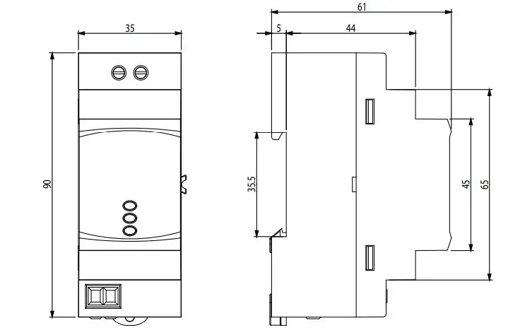
| Dimensions (mm) | Figure 7 |
| Enclosure | ABS + V0 polycarbonate |
| Weight | 115 gr |
| Protection degree | IP 51 installed IP 40 in the terminal area |
| Standards | |
| Safety requirements for electrical units for measurement, control and laborato- ry use� Part 1: General requirements� | EN 61010-1: 2010 |
| Electromagnetic compatibility (CEM)� Part 6-2: Generic standards� Immunity for industrial environments� | EN 61000-6-2: 2005 |
| Electromagnetic compatibility (CEM)� Part 6-3: Generic standards� Emission standard for residential, commercial and light industry environments� | EN 61000-6-3: 2007 |
MAINTENANCE AND TECHNICAL SERVICE
The unit does not need any type of maintenance.
In the case of any query in relation to device operation or malfunction, please contact the CIRCUTOR, SA Technical Support Service.
Technical Assistance Service
Vial Sant Jordi, s/n, 08232 – Viladecavalls (Barcelona)
Tel: 902 449 459 ( España) / +34 937 452 919 (outside of Spain)
email: [email protected]
GUARANTEE
CIRCUTOR guarantees its products against any manufacturing defect for two years after the delivery of the units.
CIRCUTOR will repair or replace any defective factory product returned during the guarantee period.
- No returns will be accepted and no unit will be repaired or replaced if it is not accom-panied by a report indicating the defect detected or the reason for the return.
- The guarantee will be void if the units has been improperly used or the storage, instal-lation and maintenance instructions listed in this manual have not been followed. “Im-proper usage” is defined as any operating or storage condition contrary to the national electrical code or that surpasses the limits indicated in the technical and environmental features of this manual.
- CIRCUTOR accepts no liability due to the possible damage to the unit or other parts of the installation, nor will it cover any possible sanctions derived from a possible failure, improper installation or “improper usage” of the unit. Consequently, this guarantee does not apply to failures occurring in the following cases:
- Overvoltages and/or electrical disturbances in the supply;
- Water, if the product does not have the appropriate IP classification;
- Poor ventilation and/or excessive temperatures;
- Improper installation and/or lack of maintenance;
- Buyer repairs or modifications without the manufacturer’s authorisation.


