![]() CSM-4 Controllable Signal Module
CSM-4 Controllable Signal Module
Instruction Manual
Installation Instructions
Model CSM-4
Controllable Signal Module
OPERATION
The Model CSM-4 Controllable Signal Module from Siemens Industry, Inc. has two fully supervised, programmable circuits. The outputs supply two Class B (Style Y) or Class A (Style Z) output circuits for the supervision and control of audible or visual notification devices such as horns, bells, strobes, etc.
Each notification circuit on a CSM-4 can be configured in one of four ways: (1) as a supervised connection to a Municipal Tie, (2) as a connection to a Leased Line remote monitoring System, (3) for releasing service per NFPA 13 and NFPA 2001, or (4) as a NAC.
Each output can be controlled automatically through the MXL program logic or manually by using the MXL keypad. Automatic control can also be time based. Each output
can be manually armed or disarmed through the MXL keypad. When any output is disarmed, the MXL LCD annunciator indicates which circuit or output, and the PARTIAL SYSTEM DISABLE LED lights until the circuit or output is armed again. The TROUBLE LED also lights.
The CSM-4 notification appliance circuits function in a Degrade mode, when the main MXL processor or the network communication link fails. Each circuit’s degrade mode of operation can be separately configured to respond to an alarm in any of the following ways:
OFF
ON CONTINUOUSLY
1 SECOND ON—1 SECOND OFF (Infinite repeat)
CSM-4 notification appliance circuit outputs can be set by using the CSG-M for any one of the following: (1) coded march time, (2) zone code, or (3) uniform Code 3 output.
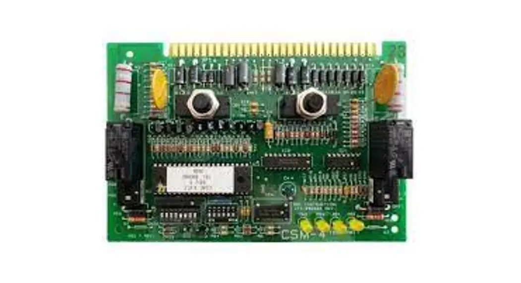
The CSM-4 has two diagnostic and two user programmable LEDs (See Figure 1). In addition, each circuit is equipped with transient and noise suppression.
INSTALLATION
Remove all system power before installation, first battery and then AC. (To power up, first connect the AC and then the battery.)
The CSM-4 module plugs into one slot on the MOM-4 Expansion Module. There are four available slots for the CSM-4 on the MOM-4 (See Figure 2). Selecting which position on the MOM-4 to use for a CSM-4 determines which contacts are available: TB1, TB2, TB3, or TB4.
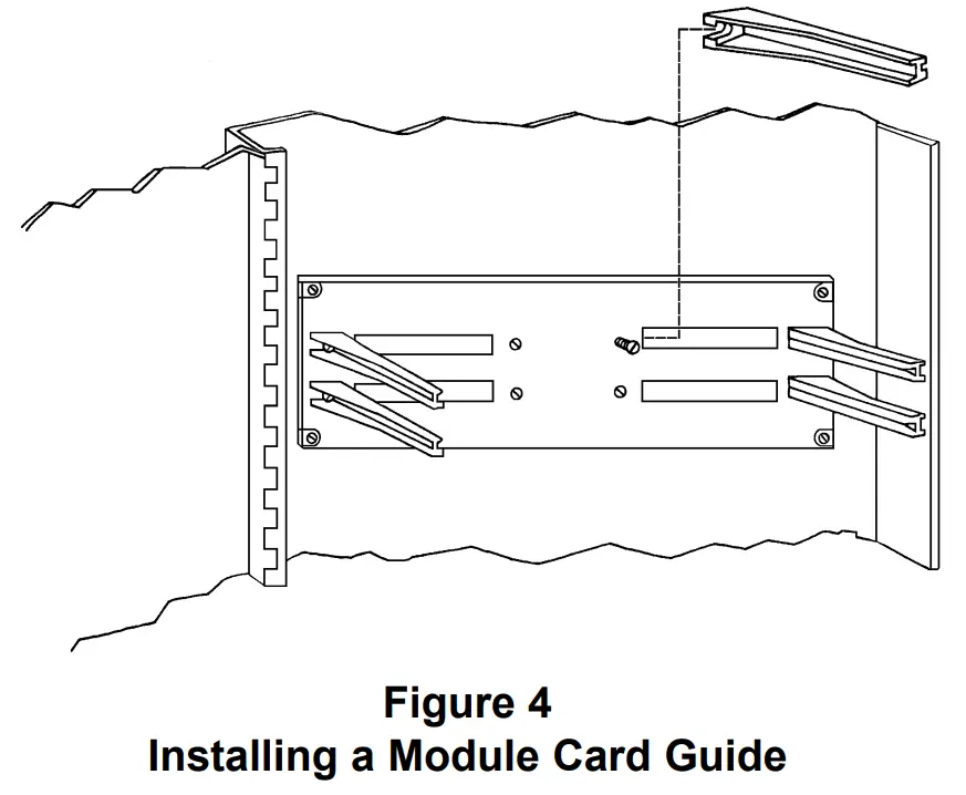
The CSM-4 is shipped with one card guide to add to the MOM-4 before the CSM-4 can be installed. Choose the position for the card guide according to which terminal block you wish to use.
To install the card guide, loosen the appropriate screw in the center area of the MOM-4 and set the card guide in place, making sure that the locating pin on the bottom of the card guide is in the hole on the MOM-4 (See Figure 4). Tighten the screw on the MOM-4 to secure the card guide in place.
Before Installing the CSM-4 Signal Module
(Refer to Figure 3.) Before installing the CSM-4 in the MOM-4, you must set the Network address, configure each circuit according to the CSG-M program [as audibles (NACs), municipal tie, leased line, or releasing service (NFPA 13 and NFPA 2001)], and set the degrade modes (trouble and alarm) as follows:
Note: To open a dipswitch, press down on the side of the dipswitch marked OPEN.
To close a dipswitch, press down on the side of the dipswitch opposite the side marked OPEN.
To open a slide switch, push the slide to the side opposite the side marked ON.
To close a slide switch, push the slide to the side marked ON. 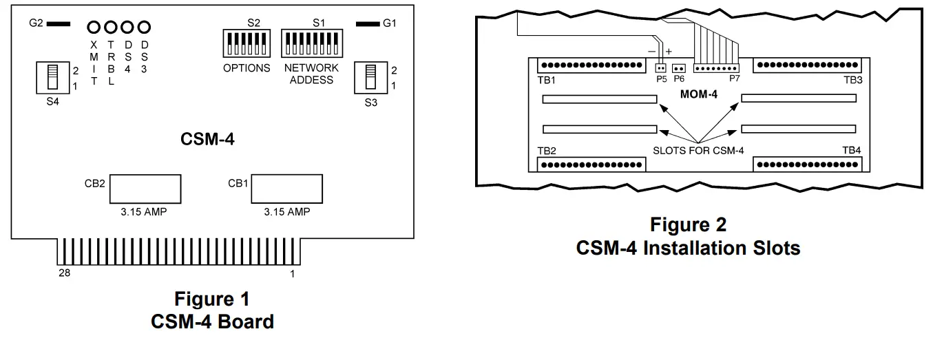 Before Installing the CSM-4
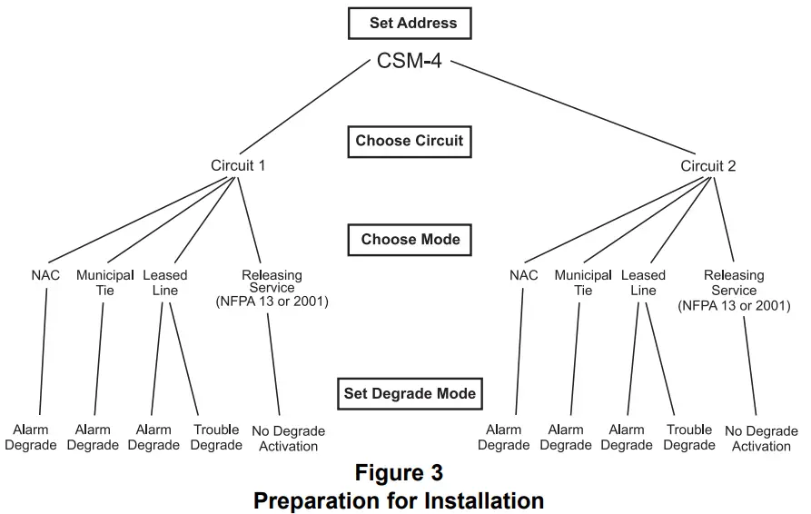
- Set the Network Address
The Network address is set on switch S1 (See Figure 1). See the CSG-M printout for the proper address. Use Table 1 to set the switches. - Set the Mode of Operation for Each Circuit
The CSM-4 has one programming slide switch and one jumper for each of its two circuits. (See slide switches S3 and S4 and jumpers G1 and G2 on the board.) Setting these slide switches and jumpers allows the selection of four possible modes of operation. These modes correspond with NFPA standards 72 Local (notification appliance circuit), Municipal Tie (municipal tie), Remote Station (leased line), and NFPA 13 and NFPA 2001 (releasing service).
Each circuit on the CSM-4 can be set independently for the type of operation desired. Table 2 shows how to set the switches and jumpers for circuits 1 and 2. The CSG-M printout shows the mode for each circuit. - Set the Degrade Modes of Operation
There are two sources of degrade activation, the degrade alarm bus and the degrade trouble bus. These two buses become active ONLY when the MXL communication network fails. Switch S2 on the CSM-4 sets the degrade mode of operation for each circuit. Each circuit operates independently in the degrade mode. Switch S2, positions SW1 and SW2, determine the degrade mode of operation when the trouble bus activates. S2, positions SW3-SW6, determines the degrade mode of operation when the alarm bus activates.
Degrade Trouble Activation
The degrade trouble bus may ONLY be used when the circuit is used as a leased line trouble notification circuit (NFPA 72 Remote Station). (See Figure 3.) When enabled, this trouble degrade mode ensures that a trouble is transmitted to the receiving station even when the MXL communication network fails.
Using the CSG-M printout, determine if either of the circuits is configured as a leased line trouble. Table 3 shows how to set S2 (SW1 and SW2) to enable the degrade trouble activation for the desired circuit.
Degrade Alarm Activation
Each circuit on the CSM-4 can be set with switch S2, positions SW3-SW6, to determine when the degrade alarm bus activates. (See Figure 3). There are three alarm degrade modes (Table 4). Each circuit can be set independently from the other. Determine which type of degrade mode you want for each circuit and set switch S2 (SW3-SW6) as shown in Table 4.
Releasing Service per NFPA 13 and NFPA 2001
No degrade activation is allowed. Set all switch positions on switch S2 to OFF (open).
| TABLE 2 SETTING THE MODE OF OPERATION (USING S3, S4 AND G1,G2)* | ||
| For Circuit 1 | S3 Position | G1 |
| Audbles (NAG] OFPA 72 Local) Munapal Tie (NFPA 72) Leased Line (NFPA 72 Renate Station) Releasing Service (NFPA 13) Releasing Service (NFPA 2001) Illegal (Results in a trouble on the CSM-4) | 1 1 2 1 1 2 | Not Cut Cut Not Cut Not Cut Not Cut Cut |
| For Circuit 2 | S4 Position | G2 |
| Authbles [NAC) (NFPA 72 Local) Muncoal Tie (NFPA 72) Leased Line (NFPA 72 Remote Station) Releasing Service (NFPA 13) Releasing Service (NFPA 2001) Illegal (Results in a trouble on the CSM-4) | 1 1 2 1 1 2 | Not Cut Cut Not Cut Not Cut Not Cut Cut |
* See Figure 1
| TABLE 3 SETTING THE DEGRADE TROUBLE MODES ON S2 | |
| For Circuit 1 | SW1 |
| Leased Line Trouble No Trouble Activation | On (Closed) Off (Open) |
| For Circuit 2 | SW2 |
| Leased Line Trouble No Trouble Activation | On (Closed) Off (Open) |
| Note: If circuit 1 or circuit 2 is not used for leased line trouble, dipswitches SW1 or SW2 must be off (open). | |
| TABLE 4 SETTING THE DEGRADE ALARM MODES ON S2 | ||
| For Circuit 1 | SW4 | SW3 |
| OFF (no degrade activation) | Off (Open) | Off (Open) |
| CONTINUOUS (active on degrade alarm) | Off (Open) | On (Closed) |
| 1 SEC ON, 1 SEC OFF (infinite repeat) | On (Closed) | Off (Open) |
| DO NOT USE | On (Closed) | On (Closed) |
| For Circuit 2 | SW6 | SW5 |
| OFF (no degrade activation) | Off (Open) | Off (Open) |
| CONTINUOUS (active on degrade alarm) | Off (Open) | On (Closed) |
| 1 SEC ON, 1 SEC OFF (infinite repeat) | On (Closed) | Off (Open) |
| DO NOT USE | On (Closed) | On (Closed) |
Note: When circuits are used for leased line supervisory, the alarm degrade modes must be set to OFF (Open).
TABLE 1
NETWORK ADDRESS PROGRAMMING
| ADDR | 8 7 6 5 4 3 2 1 | ADDR | 8 7 6 5 4 3 2 1 | ADDR | 8 7 6 5 4 3 2 1 | ADDR | 8 7 6 5 4 3 2 1 |
| 000 | ILLEGAL | 064 | OXOOOOOO | 128 | XOOOOOOO | 192 | XXOOOOOO |
| 001 | ILLEGAL | 065 | OXOOOOOX | 129 | XOOOOOOX | 193 | XXOOOOOX |
| 002 | ILLEGAL | 066 | OXOOOOXO | 130 | XOOOOOXO | 194 | XXOOOOXO |
| 003 | OOOOOOXX | 067 | OXOOOOXX | 131 | XOOOOOXX | 195 | XXOOOOXX |
| 004 | OOOOOXOO | 068 | OXOOOXOO | 132 | XOOOOXOO | 196 | XXOOOXOO |
| 005 | OOOOOXOX | 069 | OXOOOXOX | 133 | XOOOOXOX | 197 | XXOOOXOX |
| 006 | OOOOOXXO | 070 | OXOOOXXO | 134 | XOOOOXXO | 198 | XXOOOXXO |
| 007 | OOOOOXXX | 071 | OXOOOXXX | 135 | XOOOOXXX | 199 | XXOOOXXX |
| 008 | OOOOXOOO | 072 | OXOOXOOO | 136 | XOOOXOOO | 200 | XXOOXOOO |
| 009 | OOOOXOOX | 073 | OXOOXOOX | 137 | XOOOXOOX | 201 | XXOOXOOX |
| 010 | OOOOXOXO | 074 | OXOOXOXO | 138 | XOOOXOXO | 202 | XXOOXOXO |
| 011 | OOOOXOXX | 075 | OXOOXOXX | 139 | XOOOXOXX | 203 | XXOOXOXX |
| 012 | OOOOXXOO | 076 | OXOOXXOO | 140 | XOOOXXOO | 204 | XXOOXXOO |
| 013 | OOOOXXOX | 077 | OXOOXXOX | 141 | XOOOXXOX | 205 | XXOOXXOX |
| 014 | OOOOXXXO | 078 | OXOOXXXO | 142 | XOOOXXXO | 206 | XXOOXXXO |
| 015 | OOOOXXXX | 079 | OXOOXXXX | 143 | XOOOXXXX | 207 | XXOOXXXX |
| 016 | OOOXOOOO | 080 | OXOXOOOO | 144 | XOOXOOOO | 208 | XXOXOOOO |
| 017 | OOOXOOOX | 081 | OXOXOOOX | 145 | XOOXOOOX | 209 | XXOXOOOX |
| 018 | OOOXOOXO | 082 | OXOXOOXO | 146 | XOOXOOXO | 210 | XXOXOOXO |
| 019 | OOOXOOXX | 083 | OXOXOOXX | 147 | XOOXOOXX | 211 | XXOXOOXX |
| 020 | OOOXOXOO | 084 | OXOXOXOO | 148 | XOOXOXOO | 212 | XXOXOXOO |
| 021 | OOOXOXOX | 085 | OXOXOXOX | 149 | XOOXOXOX | 213 | XXOXOXOX |
| 022 | OOOXOXXO | 086 | OXOXOXXO | 150 | XOOXOXXO | 214 | XXOXOXXO |
| 023 | OOOXOXXX | 087 | OXOXOXXX | 151 | XOOXOXXX | 215 | XXOXOXXX |
| 024 | OOOXXOOO | 088 | OXOXXOOO | 152 | XOOXXOOO | 216 | XXOXXOOO |
| 025 | OOOXXOOX | 089 | OXOXXOOX | 153 | XOOXXOOX | 217 | XXOXXOOX |
| 026 | OOOXXOXO | 090 | OXOXXOXO | 154 | XOOXXOXO | 218 | XXOXXOXO |
| 027 | OOOXXOXX | 091 | OXOXXOXX | 155 | XOOXXOXX | 219 | XXOXXOXX |
| 028 | OOOXXXOO | 092 | OXOXXXOO | 156 | XOOXXXOO | 220 | XXOXXXOO |
| 029 | OOOXXXOX | 093 | OXOXXXOX | 157 | XOOXXXOX | 221 | XXOXXXOX |
| 030 | OOOXXXXO | 094 | OXOXXXXO | 158 | XOOXXXXO | 222 | XXOXXXXO |
| 031 | OOOXXXXX | 095 | OXOXXXXX | 159 | XOOXXXXX | 223 | XXOXXXXX |
| 032 | OOXOOOOO | 096 | OXXOOOOO | 160 | XOXOOOOO | 224 | XXXOOOOO |
| 033 | OOXOOOOX | 097 | OXXOOOOX | 161 | XOXOOOOX | 225 | XXXOOOOX |
| 034 | OOXOOOXO | 098 | OXXOOOXO | 162 | XOXOOOXO | 226 | XXXOOOXO |
| 035 | OOXOOOXX | 099 | OXXOOOXX | 163 | XOXOOOXX | 227 | XXXOOOXX |
| 036 | OOXOOXOO | 100 | OXXOOXOO | 164 | XOXOOXOO | 228 | XXXOOXOO |
| 037 | OOXOOXOX | 101 | OXXOOXOX | 165 | XOXOOXOX | 229 | XXXOOXOX |
| 038 | OOXOOXXO | 102 | OXXOOXXO | 166 | XOXOOXXO | 230 | XXXOOXXO |
| 039 | OOXOOXXX | 103 | OXXOOXXX | 167 | XOXOOXXX | 231 | XXXOOXXX |
| 040 | OOXOXOOO | 104 | OXXOXOOO | 168 | XOXOXOOO | 232 | XXXOXOOO |
| 041 | OOXOXOOX | 105 | OXXOXOOX | 169 | XOXOXOOX | 233 | XXXOXOOX |
| 042 | OOXOXOXO | 106 | OXXOXOXO | 170 | XOXOXOXO | 234 | XXXOXOXO |
| 043 | OOXOXOXX | 107 | OXXOXOXX | 171 | XOXOXOXX | 235 | XXXOXOXX |
| 044 | OOXOXXOO | 108 | OXXOXXOO | 172 | XOXOXXOO | 236 | XXXOXXOO |
| 045 | OOXOXXOX | 109 | OXXOXXOX | 173 | XOXOXXOX | 237 | XXXOXXOX |
| 046 | OOXOXXXO | 110 | OXXOXXXO | 174 | XOXOXXXO | 238 | XXXOXXXO |
| 047 | OOXOXXXX | 111 | OXXOXXXX | 175 | XOXOXXXX | 239 | XXXOXXXX |
| 048 | OOXXOOOO | 112 | OXXXOOOO | 176 | XOXXOOOO | 240 | XXXXOOOO |
| 049 | OOXXOOOX | 113 | OXXXOOOX | 177 | XOXXOOOX | 241 | XXXXOOOX |
| 050 | OOXXOOXO | 114 | OXXXOOXO | 178 | XOXXOOXO | 242 | XXXXOOXO |
| 051 | OOXXOOXX | 115 | OXXXOOXX | 179 | XOXXOOXX | 243 | XXXXOOXX |
| 052 | OOXXOXOO | 116 | OXXXOXOO | 180 | XOXXOXOO | 244 | XXXXOXOO |
| 053 | OOXXOXOX | 117 | OXXXOXOX | 181 | XOXXOXOX | 245 | XXXXOXOX |
| 054 | OOXXOXXO | 118 | OXXXOXXO | 182 | XOXXOXXO | 246 | XXXXOXXO |
| 055 | OOXXOXXX | 119 | OXXXOXXX | 183 | XOXXOXXX | 247 | XXXXOXXX |
| 056 | OOXXXOOO | 120 | OXXXXOOO | 184 | XOXXXOOO | 248 | ILLEGAL |
| 057 | OOXXXOOX | 121 | OXXXXOOX | 185 | XOXXXOOX | 249 | ILLEGAL |
| 058 | OOXXXOXO | 122 | OXXXXOXO | 186 | XOXXXOXO | 250 | ILLEGAL |
| 059 | OOXXXOXX | 123 | OXXXXOXX | 187 | XOXXXOXX | 251 | ILLEGAL |
| 060 | OOXXXXOO | 124 | OXXXXXOO | 188 | XOXXXXOO | 252 | ILLEGAL |
| 061 | OOXXXXOX | 125 | OXXXXXOX | 189 | XOXXXXOX | 253 | ILLEGAL |
| 062 | OOXXXXXO | 126 | OXXXXXXO | 190 | XOXXXXXO | 254 | ILLEGAL |
| 063 | OOXXXXXX | 127 | OXXXXXXX | 191 | XOXXXXXX | 255 | ILLEGAL |
WIRING
The municipal tie and leased line applications require the LLM-1 interface module. The notification appliances and leased line applications are power limited.Electrical Connections for Notification
Appliances (NFPA 72 Local) (Refer to Figure 5)
- Set switches S3 and S4 and jumpers G1 and G2 as indicated in Table 2.
- All wiring must be in accordance with Article 760 of NEC or local building codes.
- Both circuits are power limited to NFPA 70 per NEC 760.
- Electrical Ratings: Special Application
16-32V unfiltered full wave rectified
12mA max @ Supervisory
1.5A max @ Alarm - End of line device: Use EOL device, 2.2K, 1/2 watt, P/N 140-820380.
- Line Resistance: 2.1 ohms max
- For a list of Compatible Notification Appliances, refer to P/N 315-096363.
- For sychonized notification appliances, use of either a DSC, DSC-W, or PAD-3 is required.
Electrical Connections for Municipal Tie (NFPA 72) (Refer to Figure 6)
- Set switches S3 and S4 and jumpers G1 and G2 as indicated in Table 2.
- All wiring must be in accordance with Article 760 of NEC or local building codes.
- Both circuits are not power limited.
- Electrical Ratings:
Trip Coil: 14.5 ohms
Trip Current: 220 to 320mA DC (momentary)
Supervisory Current: 12mA DC
Voltage: 18 to 31 VDC
The total loop resistance from the LLM-1 to the
Municipal Tie, including the 14.5 ohms in the
Municipal Tie, should not exceed 22.5 ohms. - Minimum emergency power:
60 hour standby
5 minute alarm
Refer to Wiring Specification for MXL, MXL-IQ and MXLV Systems, P/N 315-092772 revision 6 or higher, for additional wiring information.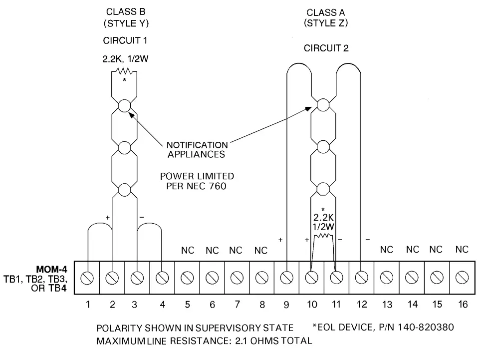 NOTE:
NOTE:
1. Positive and negative ground faults detected at <30K ohms for terminals 1-4, 9-12.
Figure 5
CSM-4 Loop Wiring for Supervised Notification Appliance Circuit
Refer to Wiring Specification for MXL, MXL-IQ and MXLV Systems, P/N 315-092772 revision 6 or higher, for additional wiring information.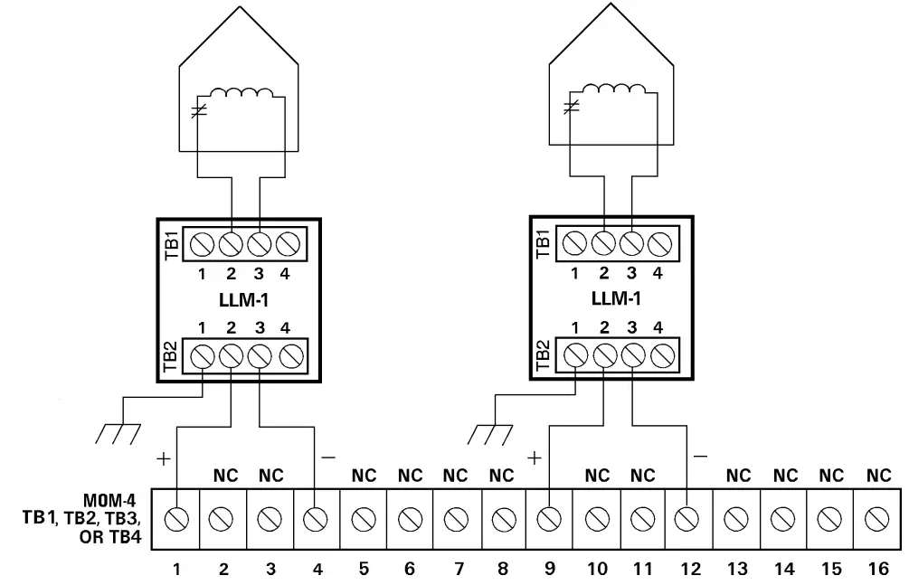 Figure 6
CSM-4 Loop Wiring of Supervised Municipal Tie
NOTES:
- Polarity shown in supervisory state.
- The total loop resistance from the LLM-1 to the Municipal Tie, including the 14.5 ohms in the Municipal Tie, should not exceed 22.5 ohms.
- Either circuit may be used.
- Municipal Tie circuits are not power limited.
- Positive and negative ground faults detected at <30K ohms for terminals 1-4, 9-12.
Electrical Connections for Leased Line (NFPA 72 Remote Station) (Refer to Figure 7)
- Set switches S3 and S4 and jumpers G1 and G2 as indicated in Table 2.
- When a CSM-4 circuit is used as a Leased Line trouble output, SW1 and SW2 on switch S2 must be set. These positions permit the degrade trouble bus to activate the trouble line. Refer to Table 3 to set them.
- All wiring must be in accordance with Article 760 of NEC or local building codes.
- Both leased line circuits are power limited to NFPA 70 per NEC Article 760.
- Leased Line circuit rating: 24 VDC open circuit Load must be a compatible polarity reversal labeled remote station receiver unit Rated current: 3mA to 9mA, alarm/supervisory External circuit resistance: 2K to 5K ohms
- Minimum emergency power:
60 hour standby
5 minute alarm
Note: Intended for connection to a polarity reversal circuit of a control unit at the protected premises having compatible ratings.
Electrical Connections for Releasing Service (per NFPA 13 and NFPA 2001) (Refer to Figure 8)
- Set switches S3 and S4 and jumpers G1 and G2 as indicated in Table 2.
- Set all positions of switch S2 to OFF (OPEN).
- All wiring must be in accordance with Article 760 of NEC or local building codes.
- Releasing circuits are not power limited.
- Solenoids are supervised for opens and shorts.
- Electrical Ratings:
Supervisory Current: 12mA max
Alarm Current:1.5A max
Wire Resistance: 3 ohms max - Compatible Solenoids:
When using a UL approved power supply, refer to Table 5 in Figure 8 for a list of compatible solenoids.
Refer to Wiring Specification for MXL, MXL-IQ and MXLV Systems, P/N 315-092772 revision 6 or higher, for additional wiring information.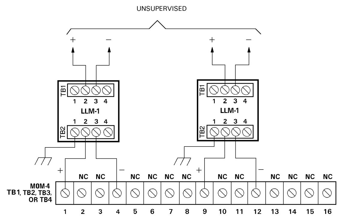
NOTES:
- Polarity shown in normal state.
- Leased line circuits are power limited per NEC 760
- External resistance 2K-5K Ohms.
- Positive and negative ground faults detected at <30K ohms for terminals 1-4, 9-12.
Figure 7
CSM-4 Leased Line Circuit
Electrical Ratings
| Active 5VDC Module Current | 10mA |
| 24VDC Module Current* | 30mA + 20mA per active output |
| Standby 24VDC Module Current | 35mA (includes end of line devices) |
*Does not include any current drawn by notification appliances.
For additional information on the MXL/MXLV System, refer to the MXL/MXLV Manual, P/N 315-092036.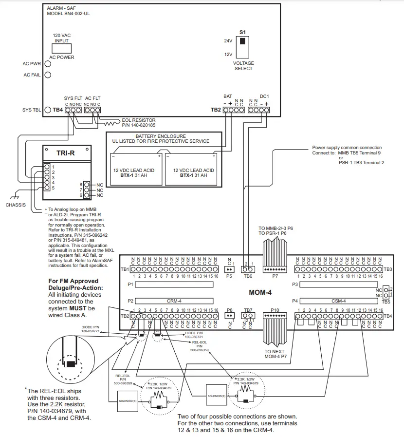
Figure 8
MXL Releasing Service Wiring Diagram with AlarmSAF Power Supply (per NFPA 13 and NFPA 2001)
| Application | Make | Solenoid Model or Part Number | Number of Solenoids in Series | Maximum #of Circuits per MOM-4 |
| NFPA 13 (Pre-Action Deluge) | Skinner | LV2LBX25 | One 24 VDC | 4 |
| ASCO | T8210A107 | One 24 VDC | 4 | |
| ASCO | R8210A107 | One 24 VDC | 4 | |
| Skinner | 7321GBN99N00N0C111C2 | One 24 VDC | 4 | |
| NFPA 2001 (HFC-227ea) | ASCO | CPYEC-6 HV218532-6* | Four 6 VDC | 2 |
| SNAPTITE | CPYEC-6 P/N 2823A-2NB-A4F4* | Four 6 VDC | 2 | |
| SNAPTITE | CPYEC-12 P/N 2823A-2NB-A4F5** | Two 12 VDC | 4 | |
| SNAPTITE | CPYEC1200-24 P/N 932594B | One 24 VDC | 4 | |
| SNAPTITE | CPYEC-24 P/N 2823A-2NB-A4F6 | One 24 VDC | 4 |
Any solenoid not deserted in the table is not permitted.
Four series comected 6V solenoids must be used.
“Its not permitted to ma one 12 VDC solenoid with any combination of the 6 VDC solenoids.
Refer to Wiring Specification for MXL, MXL-IQ and MXLV
Systems, P/N 315-092772 revision 6 or higher, for additional wiring information.
Battery capacity determined by CSM-4 circuits in supervisory circuits:
1-3…………………………. 7Ah
4-5…………………………..10Ah
6-8……………………………..15Ah
NOTES:
- Use only Pre-Action/Deluge solenoids from Table 5.
- Solenoids supervised for opens and shorts.
- Polarity shown in supervisory condition.
- Releasing circuits are not power limited.
- Configure CSM-4 circuits as Steady NAC in CSG-M.
- Each MOM-4 must be powered from a separate ALARM-SAF power supply.
- Set all positions of S2 on the CSM-4 to OFF (OPEN).
- When programming releasing applications in the CSG-M, the abort function must override the manual circuit abort.
- On power up, MXL first then AlarmSAF; on power down, AlarmSAF first then MXL.
- Alarm SAF is rated for 4A.
- Maximum of 4 Releasing Circuits per MOM-4.
- MOM-4 is limited to releasing circuits only.
- REL-EOL module (P/N 500-696359) is required for supervision of open and short circuits on the releasing circuit. REL-EOL must be close nippled to the last solenoid in the loop.
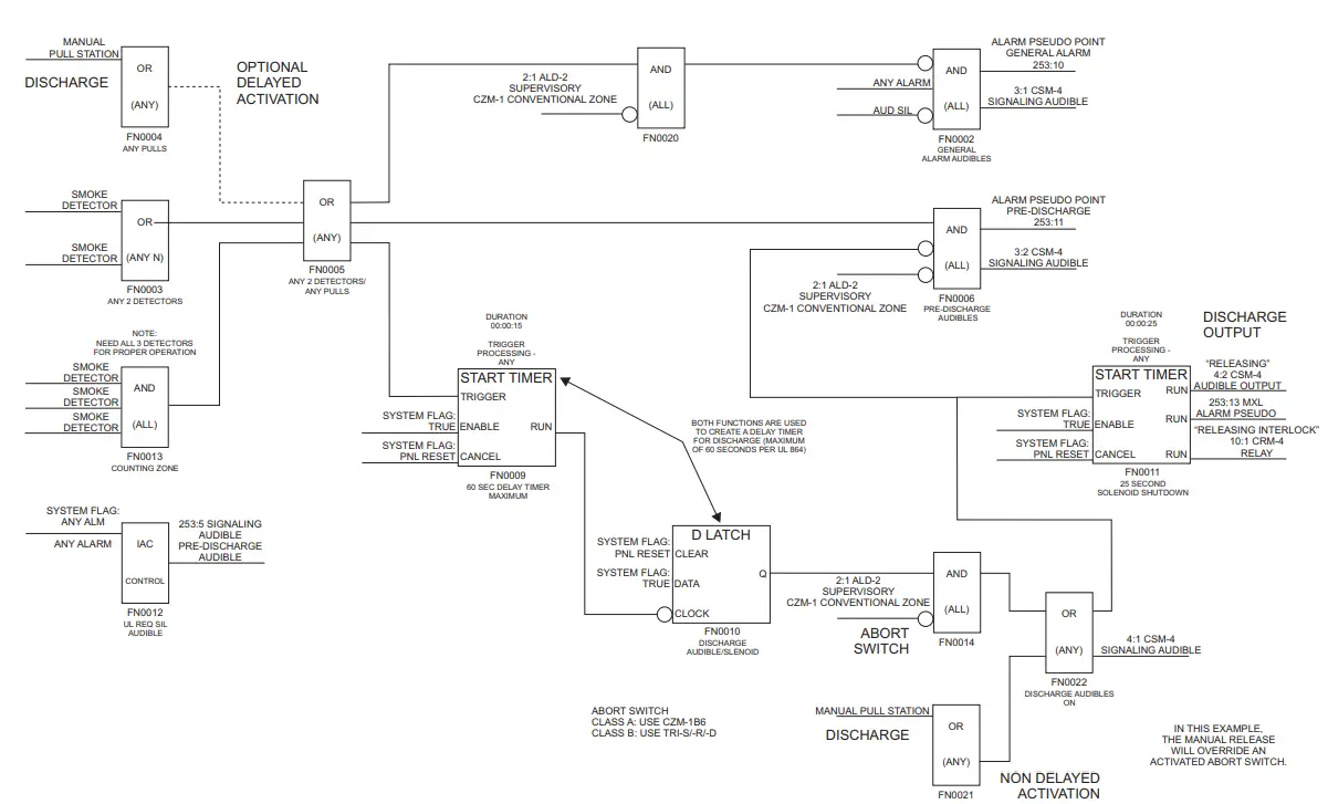 Figure 9
Sample MXL Releasing Service Flow Diagram
NOTE PER UL 864, MANUAL RELEASE CAN OVERRIDE PRE-DISCHARGE DELAYS;
HOWEVER, THE MAXIMUM DELAY FROM ACTIVATION OF THE SWITCH TO ACTIVATION OF THE RELEASING DEVICES IS 30 SECONDS.
![]() P/N 315-090854-17
P/N 315-090854-17
Siemens Industry, Inc.
Building Technologies Division
Florham Park, NJ
Siemens Building Technologies, Ltd.
Fire Safety & Security Products
2 Kenview Boulevard
Brampton, Ontario
L6T 5E4 Canada
firealarmresources.com


