![]() CSM2400FH Module
CSM2400FH Module
User Manual
| Revision | Modified | Checked | Module Name | ||
| Date | By | Date | By | CSM2400FH | |
| Description | |||||
| 2400 MHz RF Module with Frequency Hopping | |||||
| Remarks | |||||
| Item Number | |||||
GENERAL DESCRIPTION
The CSM2400 module from Hetronic is a Frequency Hopping Spread Spectrum transmitter. It transmits data in the 2.4GHz spectrum in a transparent manner. To ensure a reliable connection, the radio link is fully redundant, with two distinct radios. Once the modules are paired, they will send data through a pseudo-random channel sequence utilizing packet-based encryption.
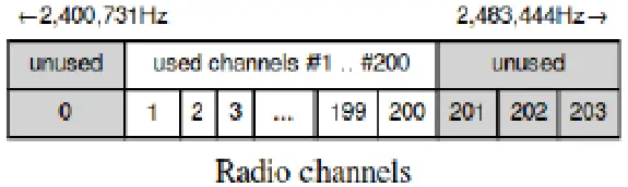
2.1.2 Band Plan
- Channel spacing: 405 kHz (precise 405,456.543)
- 204 channels possible
- To protect band borders, only 200 channels are in use (#1 … #200)
| Start Frequency (Hz): | 902175000 |
| Middle Frequency (Hz): | 915000000 |
| Stop Frequency (Hz): | 927825000 |
FCC COMPLIANCE NOTIFICATIONS
FCC Part 15 Notice
“This device complies with part 15 of the FCC Rules. Operation is subject to the following two conditions:
- This device may not cause harmful interference, and
- this device must accept any interference received, including interference that may cause undesired operation.”
ISED RSS-Gen Notice
“This device complies with Industry Canada’s license-exempt RSS. Operation is subject to the following two conditions:
- This device may not cause interference; and
- This device must accept any interference, including interference that may cause undesired operation of the device.
For Canadian, User
CAN ICES-3 (B)/NMB-3(B)”
NOTE: This equipment has been tested and found to comply with the limits for a Class B digital device, pursuant to Part 5 of the FCC Rules. These limits are designed to provide reasonable protection against harmful interference in a residential installation. This equipment generates uses and can radiate radio frequency energy and, if not installed and used in accordance with the instructions, may cause harmful interference to radio communications. However, there is no guarantee that interference will not occur in a particular installation.
If this equipment does cause harmful interference to radio or television reception, which can be determined by turning the equipment off and on, the user is encouraged to try to correct the interference by one of the following measures:
- Reorient or relocate the receiving antenna.
- Increase the separation between the equipment and receiver.
- Connect the equipment into an outlet on a circuit different from that to which the receiver is connected.
- Consult the dealer or an experienced radio/TV technician for help.
“Changes or modifications not expressly approved by the party responsible for compliance could void the user’s authority to operate the equipment”
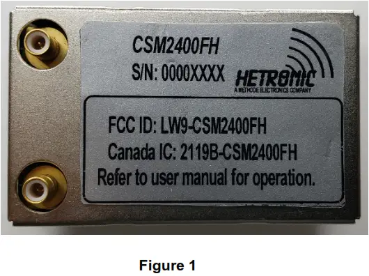
WARNING: The OEM must ensure that FCC labeling requirements are met. This includes a clearly visible label on the outside of the OEM enclosure specifying the appropriate Hetronic FCC identifier for this product below.
“Contains FCC ID: LW9-CSM2400FH”
“Contains IC: 2119B-CSM2400FH”
RF Exposure
The Hetronic CSM2400FH meets the RF exposure requirement of low-power devices under portable operation. This device should be operated with a minimum distance of 20mm (2 cm) between the antenna and your body. Do not touch or move the antenna while the unit is transmitting or receiving.
NOTE: FCC/IC warnings are to be incorporated into the manuals as provided to the end-user.
Setup and Adjustment Procedure
The CSM2400FH is factory tested and set up during the approved end control process. Any settings and adjustments are performed by factory-trained personnel. No final adjustments are required by the end-user.
Approved Antenna List
Item | Part Number | Mgf. | Type | Gain (dB) |
| 1 | 56506605 | Hetronic | Omnidirectional | Unity |
| 2 | ANT-2450-3-0 | Doodle Labs | Omnidirectional | 3 bBi |
Label Placement
The actual labeled and assembled unit will look similar to the one pictured below:
Microcontroller Interface
Pin Layout
CSM FH uses a pin layout compatible with legacy Hetronic radio modules. This layout allows the CSM FH to be used in devices that accept the direct installation of the legacy module. Please note, however, that the pins are not utilized the same way as the legacy radios, and software modification of devices is required to make use of the CSM FH radio module. 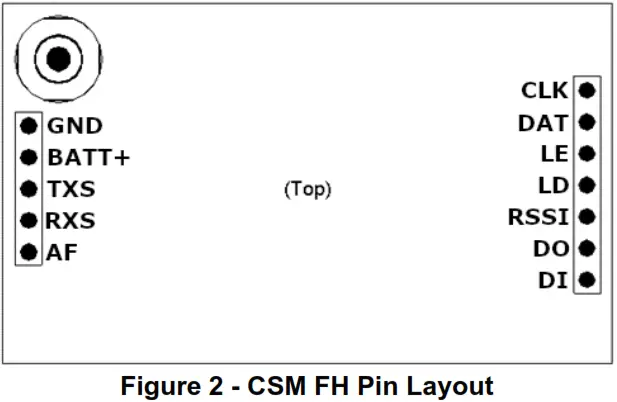
Pin Description
Pin Label | Type | FH Pin Description |
| GND | S | Negative Supply Input, 0 V DC (Ground) |
| BATT+ | S | Positive Supply Input, 2.9-5.5 V DC |
| TXS | IPU | Not Used1 |
| RXS | IPU | Not Used1 |
| AF | O | Not Used3 |
| CLK | IPU | Not Used1 |
| DAT | I | Not Used1 |
| LE | I | Not Used1 |
| LD | O | Not Used2 |
| RSSI | O | Not Used3 |
| DO | O | UART command data out (CSM -> Host) |
| DI | IPU | UART command data in (Host -> CSM) |
(S = Supply, I = Input, O = Output, B = Bi-Directional, PU = Pullup, PD = Pulldown)
Table 1 – CSM FH Pin Descriptions
Notes:
- These unused pins are pulled to BATT+ internally.
- The LD pin is driven LOW under CSM FH operation.
- The RSSI and AF pins are used for diagnostic output for the FHSS sub-system.
TECHNICAL SPECIFICATION
POWER | VALUE | |
| Supply Voltage | 2.8 to 4.2 VDC | |
| Transmit mode Supply Current | 90 mA | Vcc= 4V, 20 BBM output, 50-ohm load. |
| Receiver Mode | 40 mA | Vcc= 4V |
PROTOCOL | ||
| Data Rate | ≥25 kbps | |
| Buffered | ≥1024 Bytes | |
| PTP | Yes | |
RF | ||
| Diversity | Full | |
| Encryption | Yes | |
| RSSI and/or LQI available to all nodes | Yes | |
| Channels available | 200 | |
| Proprietary communications protocol | Yes | |
| Circular Antenna Polarization (external), PCB RF connector only | RHCP, RF connector SMB type | |
| Adjustable RF power | ≤ 20 dBm | |
| Class 1 receiver blocking | Complies to ETSI 300 328 V2.2.1 (2019-04), clause: Page 26: 4.3.1.12 Receiver Blocking Page 27: 4.3.1.12.4.2 Receiver Category 1 | |
| Receiver Noise Figure | TI LNA: 4,8 dB incl. antenna switch | |
| Robust front-end filtering | Yes | |
| Frequency Hopping – zero application configuration | Yes | |
OPERATING ENVIRONMENT | ||
| Operating Temperature | -40° to +85° C |
| Storage Temperature | -40° to +105° C | |
| Operating Humidity | 20% to 70%, non-condensing | |
| Storage Humidity | 95%, non-condensing | |
MECHANICAL | ||
| PCB Material | FR-4 (Prepreg 7628 AT05 47% Resin) | |
| Connections | ||
![]()


